
Abstract
The review is aimed at presenting a unified approach in understanding the mechanism of non-equilibrium grain boundary segregation, which can satisfactorily describe the three types of intergranular embrittlement, namely, reverse temper embrittlement of steels, intergranular corrosion embrittlement of stainless steels and intermediate temperature embrittlement of metals and alloys. The review starts with a broad perspective of non-equilibrium grain boundary segregation, including thermally induced non-equilibrium grain boundary segregation and stress induced non-equilibrium grain-boundary segregation. Next, it focuses on the recent progress made in the non-equilibrium grain boundary segregation, including (1) critical time, (2) segregation peak temperature, (3) segregation peak temperature movement for thermally induced and stress induced non-equilibrium grain boundary segregation, and (4) the effect of temperature difference on thermally-induced non-equilibrium grain boundary segregation. Next, the attention is focused on the grain boundary coverage of elements and intergranular embrittlement phenomena. Three types of intergranular embrittlement is analysed in terms of (1) the ductility healing effect induced by the critical time, (2) embrittlement peak or ductility trough induced by the segregation peak temperature, (3) embrittlement peak or ductility trough movement induced by the segregation peak temperature movement and (4) widening and deepening of ductility trough induced by differences in temperature. These experimental phenomena concerning the three types of intergranular embrittlement are consistent with the models of thermally induced and stress induced non-equilibrium grain boundary segregations of impurities, instead of precipitation or equilibrium grain boundary segregation. Towards the end, we visit the subject of grain boundary segregation and associated embrittlement process from the viewpoint of fracture resistance and briefly discuss different perspectives that are of practical significance.
List of symbols
constant
the Burger’s vector
Norton coefficient
grain boundary concentration at critical time
equilibrium concentration of solute at the grain boundaries
concentration of solute within the grains

equilibrium vacancy concentration at grain boundaries

grain boundary vacancy concentration induced by the tensile stress
the diffusivity
diffusion coefficients for complexes under or in absence of applied tensile stress
diffusion coefficients for solute atoms under or in absence of applied tensile stress
the elastic or Young’s modulus

the embrittlement sensitivity in K/at-% of solute at the grain boundary
formation energy of vacancy solute atom complex
vacancy formation energy
the elastic or Young’s modulus of grain boundary region
the formation energy of a vacancy in the boundary region
intergranular Auger peak to peak height of an element normalised with the Auger peak to peak height of Fe
a constant
a constant coefficient as a geometric factor
grain radius
gas constant
critical time
effective time
temperature of melting point
solution treatment temperature
the Boltzmann constant
bulk concentration of phosphorus
bulk concentration of C
excess interfacial solute coverage (concentration of segregant per unit area at the interface)
the ideal work of interfacial separation
the work of separation of the clean interface
critical time constant
the rate of grain boundary segregation of sulphur
the creep rate

the free energies of segregation of the solute to the boundary

grain boundary segregation free energy of carbon

the segregation free energy of phosphorus

the free energies of segregation of the solute to free surface
decrease in the chemical potential
grain boundary concentration of P and C respectively
applied stress
the yield strength
the atomic volume
Introduction
Intergranular embrittlement in the context of this review includes reverse temper embrittlement (RTE) of steel, intergranular corrosion embrittlement (ICE) of stainless steels and intermediate temperature embrittlement (ITE) of metals and alloys. They occur ubiquitously in metals and alloys. The mechanisms associated with the different forms of intergranular embrittlement have been unclear for several decades.
RTE, a generic problem in iron based alloys, is characterised by reduction in cohesion strength of grain boundaries because of impurity or solute atom segregation. RTE generally occurs during the heat treatment cycle, which involves an isothermal hold in the temperature range of 300–600°C, after quenching from a higher temperature. There is ample evidence in the literature to suggest that RTE occurs in the presence of impurity elements,1, 2 notably P, S, Sb, Sn and As. These impurities led to RTE even when they were present in trace amounts.3 This fact implies that the occurrence of RTE is related to impurities in steels. Furthermore, a ductility healing effect, ‘overaging’, is associated with RTE in steels, which is the degree of embrittlement initially increases, but is followed by a decrease with temper time at a constant temperature.1
ICE of stainless steels refers to the localised attack at the grain boundaries in certain corrosive environments, which results in loss in strength and ductility. This type of corrosion is observed in different types of steels and is particularly severe when the steel is subjected to sensitisation in the temperature range of 450–900°C following solution annealing.4 This illustrates that ICE occurs primarily during a heat treatment cycle involving isothermal holding for a certain duration at a constant temperature in the range of 450–900°C (sensitisation treatment) after quenching from a higher temperature. In this regard, Chaudron5 and Armijo6 showed that high purity alloys are immune from ICE. Aust et al. 7 and Armijo6 showed that both excess grain boundary hardening and intergranular corrosion are observed in a solution treated type 304 austenitic steel. However, when a high purity austenitic stainless steel was tested, there was no excess grain boundary hardening and no evidence of intergranular corrosion. Schlueter et al. 8 pointed out by comparing results from different experimental methods that ICE attack increases with increasing impurity concentration, element sulphur.8 The preceding experiments clearly revealed that the occurrence of ICE is related to the impurities present in the alloys. A ductility healing effect and the restoration of the corrosion resistance also occurs when sensitisation is extended to longer period.9
Almost all ductile metals and alloys have a ductility trough in the intermediate temperature range, which is referred to as ITE or hot ductility loss. The ITE is generally characterised by reduction in area by fracture (RA) or elongation at fracture in elevated temperature tensile tests. It is important to note that fracture generally occurs along the grain boundaries. The tensile test specimens experience a cooling from a higher temperature prior to the tensile test.10, 11 Furthermore, based on standard test procedure for elevated temperature tensile tests of metallic materials,12 it is specified that the hold time at test temperature before the commencement of tensile test should not be less than 20 min. Thus, ITE occurs usually during the heat treatment cycle when the sample is isothermally held at a temperature within the intermediate temperature range after cooling from higher temperature. In 1961, Bieber and Decker13 proved that high purity Ni is immune to ITE, while commercial purity Ni with added impurities witnessed ITE. Kraai and Floreen14 observed that trace sulphur of less than 5 ppm did not induce ITE in Ni–S alloy. But an increase in the S content of this alloy decreased RA and increased ITE. Recently, Zheng et al. 15 verified that a Ni (Bi) alloy with 25 wt-ppm Bi experienced ITE with a minimum ductility between 700 and 750°C, while high purity Ni exhibited increase in elongation with increase in temperature. The TEM observations confirmed the absence of intergranular precipitates in Ni (Bi) alloy after heat treatments.15 In Liu et al.’s experiments,16 high purity iron with S less than 2 ppm exhibited excellent hot ductility at all test temperatures between 400 and 900°C. Addition of 5 ppm S led to drop in hot ductility between 600 and 700°C. Further increase in the S content in the high purity iron decreased RA, and widened the temperature range of ITE.16 In high purity Cu–10Ni alloy, with average Pb content as low as 18 ppm, significant ITE was indeed observed, while no ITE was observed when the average Pb content was less than 0·7 ppm.17 Horikawa et al. 18 reported that when the Na content of Al–5·5 mol.-%Mg alloy is reduced to 0·01 ppm, the ITE of this alloy completely disappeared even though its average grain size was as large as 300 μm. The aforementioned experiments confirmed that the occurrence of ITE was indeed related to the presence of trace impurities in alloys. ITE can be eliminated when the aging time is increased in the vicinity of the temperature at which the ductility minimum occurs. The restoration of ductility, induced by prolonging the aging time at the intermediate temperature, is referred to as the healing effect of ITE.19
As indicated above, it is clear that these three types of intergranular embrittlement, RTE, ICE and ITE, occur during a similar heat cycle, namely, when the specimens are isothermally held at a lower temperature for a certain time after quenching from a higher temperature. Moreover, they all relate to trace impurities in steels or alloys and have a ductility healing effect during the isothermal holding. These facts imply existence of a universal mechanism, which can explain all the three types of grain boundary embrittlement. The progress in non-equilibrium grain boundary segregation theory during the last 30 years, which includes thermally induced and stress induced segregation, has provided a fundamental basis to propose a unified mechanism.11,20 – 27
In the present paper, we first outline the theory of non-equilibrium grain boundary segregation. Next, the consistency of this theory with the experimental results of RTE, ICE, and ITE is reviewed. It is impossible that all the aspects relating to intergranular embrittlement can be dealt with in a single review. However, we underscore that the majority of the experimental results on intergranular embrittlement can be explained using the model of non-equilibrium grain boundary segregation. While the primary focus is on steels, but in the last two sections, particular effort is made to establish a link between intergranular segregation and mechanical properties, a behaviour extended to non-ferrous alloy systems. The future directions are outlined in the end.
Theoretical framework of non-equilibrium grain boundary segregation
In this review, non-equilibrium grain boundary segregation includes thermally-induced non-equilibrium grain boundary segregation (TNGS)20 – 23 and stress induced non-equilibrium grain boundary segregation (SNGS).20,24 – 27 We review the progress in the understanding of these two phenomena in the last 30 years in this section to obtain a basis for the universal mechanism of RTE, ICE and ITE. An alternative to non-equilibrium thermal condition is neutron irradiation,28 but is beyond the scope of this review.
Thermally induced non-equilibrium grain boundary segregation
Grain-boundary composition significantly influences the mechanical properties of polycrystalline materials (see the sections on ‘Implications and applications to other ferrous and non-ferrous alloy systems: stress induced segregation and intergranular decohesion’ and ‘Relationship between grain boundary segregation processes and fracture resistance’). There is considerable evidence in ferritic and austenitic steels that the amount and rate of segregation to grain boundaries of both impurity and alloying elements depends on the bulk chemical composition of the material. For example, in commercial steels, major alloying elements and minor impurity elements exhibit complex interactions, ultimately influencing grain boundary chemistry (the sections on ‘Implications and applications to other ferrous and non-ferrous alloy systems: stress induced segregation and intergranular decohesion’ and ‘Relationship between grain boundary segregation processes and fracture resistance’). However, alloying and impurity elements can be divided into five broad categories based on the changes in local grain boundary composition, which are known to have an influence on the fracture and mechanical properties of alloys and steels. The five categories are: embrittling element, segregation enhancer, grain boundary cohesion enhances, cosegregation with embrittling element and segregation inhibitor. This is illustrated in the periodic table of elements in Fig. 3.6 of Ref. 28.
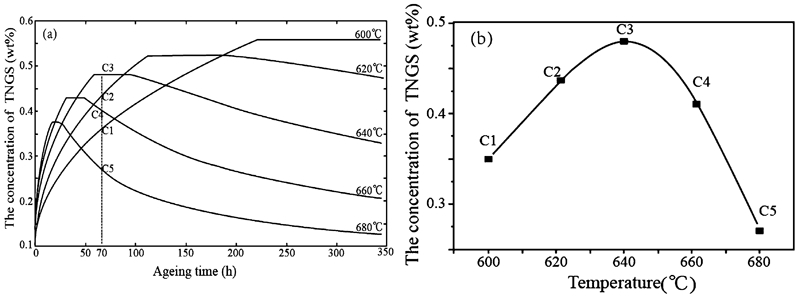
a A representative example summarising the results of concentrations of phosphorus TNGS in steel calculated using equations (2)–(5) at aging temperatures of 600, 620, 640, 660 and 680°C after quenching from 1050°C. The vertical broken line is for the aging time of 70 h.11 b TNGS concentrations of phosphorus in steel aged at 600, 620, 640, 660 and 680°C for 70 h after quenching from solution temperature of 1050°C11
In 1957, McLean29 first proposed the Langmuir–McLean segregation equation for equilibrium grain boundary segregation (EGS). The equation predicted that the segregation of a second atom species to grain boundaries in a polycrystalline material increases with decreasing temperature.28 In the late 1960s, Aust et al. 30 and Anthony31 proposed another grain boundary segregation mechanism. In 1972, Williams et al. 32 provided first experimental results on segregation of boron in steel to confirm the mechanism of segregation. When type 316 steel was solution treated at the normal temperature of 1050°C and cooled in a stream of cold argon (50°C s−1), it was observed that higher the solution treatment temperature, the greater the amount of boron segregated to grain boundaries after cooling in argon. This behaviour was opposite to that predicted by Langmuir–McLean equilibrium segregation equation.28 Thus, it was referred to as thermally induced non-equilibrium grain boundary segregation.
Critical time
TNGS is considered to be a consequence of the formation of solute vacancy complex within the matrix, where the three parts: solute atom (I), vacancy (V) and their recombined complex (C) are in equilibrium with each other,20,
33,
34 such that
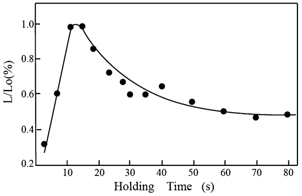
Variation of L/L o with isothermal hold time at 1050°C in an Fe–30Ni(B) alloy All samples were water quenched to 0°C after isothermal hold at 1250°C for 0·5 h. L o is the total length of the grain boundaries per unit cross-section area of the sample and L is the length of the grain boundaries in the same area in which boron segregates by PTA.23, 35
The critical time t
c is given by21,
23,
33

When the holding time at a particular temperature after quenching was longer than the critical time, the TNGS concentration of impurities decreases, and thus, the intergranular embrittlement induced by the impurities also decreases on prolonging the holding time at a particular temperature. This is a ductility healing effect and is validated experimentally in the next section.
The relationship between the critical time and holding temperature after quenching was calculated from equation (2). An example for the case of phosphorous in steel is presented in Fig. 2.20 It may be noted from Fig. 2 that the critical time increases with decreasing holding temperature after quenching. This is universally true for TNGS and was experimentally confirmed, for example B in Fe–Ni alloy,48 P in 2·6NiCrMoV steel49, 50 and P in 304L austenitic stainless steel.51
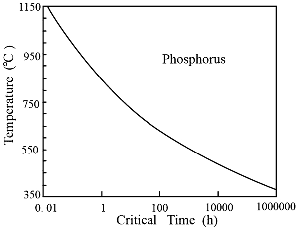
An example of the relationship between critical time and holding temperature after quenching predicted using critical time equation (2) for phosphorus in steel20
Segregation peak temperature
When samples are maintained at a solution treatment temperature T
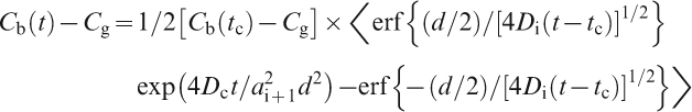
0 and then cooled quickly to a lower temperature T, the relationship between the maximum concentration of TNGS, at temperature T and the cooling temperature difference, T
0–T, was formulated20,
22,
52 as
The TNGS isothermal kinetic equations were derived for samples aged at temperature T
i+1 after quenching from a higher temperature T
i.20,
21 When the aging time is shorter than the critical time (t<t
c) at temperature T
i+1, then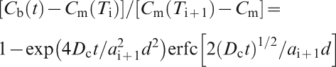
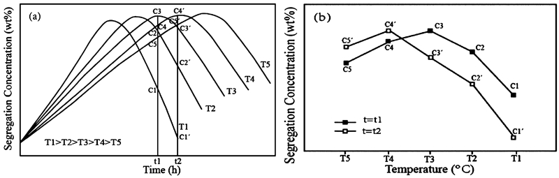
Equations (2)–(5) have been used to analyse the experimental data in Refs. 36 and 53–55 and indicated a good conformity with the measured values of grain boundary concentration. In Fig. 3a , the kinetic plots for P TNGS in steel, were obtained using equations (2)–(5) for different aging temperatures after quenching from solution temperature 1050°C for P TNGS in steel.11, 44 The vertical broken line in Fig. 3a indicates the aging time of 70 h, which is close to the critical time at temperature 640°C. The TNGS concentrations of P for aging times of 70 h at 600, 620, 640, 660 and 680°C are the concentrations of the intersecting points of the vertical broken line with the kinetic plots, C1, C2, C3, C4 and C5 respectively. They are shown in Fig. 3b as a function of aging temperatures. A maximum concentration (peak) of C3 is obtained at 640°C in Fig. 3b because aging time of 70 hours is close to the critical time of P TNGS at 640°C.11, 44 Clearly, the TNGS concentration depends on how close the aging time is to the critical time. When the aging time is close to the critical time, the TNGS concentration is higher, irrespective of whether the material is under- or overaged in relation to the critical time.
For such a thermal cycle, when the sample is held for a particular time at various temperatures after quenching from a higher temperature, a hold temperature must exist at which the TNGS concentration of the solute attains a maximum (peak). The critical time of this hold temperature is equal or close to the hold time, as presented in Fig. 3, and is called the TNGS peak temperature. This characteristic of TNGS was verified for example P in steels44, 45, 51 and S and Mg in Ni–Cr–Fe alloy,40, 42, 56 and provides a primary basis for proposing the mechanism of RTE, ICE and ITE, as discussed in the section on ‘Universal mechanism of intergranular embrittlement’.
Movement of segregation peak temperature
The critical time of TNGS increases with decreasing isothermal temperature (Fig. 2). As emphasised above, the TNGS concentration depends on how close the aging time is to the critical time. It may be noted from Fig. 3 that the peak of TNGS concentration occurs at 640°C, when the isothermal holding time at different temperatures is 70 h; and is 620°C when the holding time is about 100 h. Thus, for such a thermal cycle, when the material is isothermally held for identical time at different temperatures after quenching from a higher solution temperature, the TNGS peak temperature moves to a lower (higher) temperature for longer (shorter) holding times at different temperatures. This is referred to as the movement of TNGS peak temperature, which is an inevitable result deduced from equations (2)–(5).
It can be inferred from the movement of TNGS peak temperature that the peak of RTE or ICE moves to a higher (lower) temperature when the tempering or sensitising time at different temperatures decreases (increases) after quenching from a higher temperature. This inference is experimentally verified in section on ‘Universal mechanism of intergranular embrittlement’.
Effect of temperature difference
The relationship between the maximum concentration of TNGS at aging temperature T and the cooling temperature difference T 0−T was calculated using equation (3) for the case of rapid quenching from solution temperature T o to the aging temperature T. and is presented in Fig. 4. It may see that the maximum concentration of TNGS increases monotonically, when the cooling temperature difference T o−T increases. The effect of TNGS temperature difference is another characteristic of TNGS and is a thermodynamic property, which is not related to the cooling rate. In the late 1960s, Aust57 observed that when the solution treatment temperature was higher, the level of grain boundary segregation was also higher after cooling to the room temperature. This is contradictory to McLean’s theory and is the effect of TNGS temperature difference. Aust57 initiated the investigation on TNGS by finding this effect. In 1987, Xu22 formulated the effect in terms of equation (3). The effect of TNGS temperature difference was experimentally confirmed in different alloy systems.47,49,58 – 61
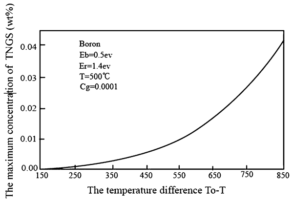
The relationship between maximum TNGS concentration C m and the temperature difference T o−T, calculated from equation (3) on rapidly quenching from solution temperature T o to the aging temperature T 20
Figure 5 shows kinetic plots calculated using equations (2)–(5) at aging temperatures of 873, 923 and 973 K after quenching from solution temperatures of 1373, 1473 and 1573 K respectively for P TNGS in steels. The vertical line in Fig. 5 indicates the aging time of 70 h, which is close to the critical time at temperature 923 K. The TNGS concentrations of phosphorus for aging time of 70 h at 873, 923 and 973 K after quenching from solution temperatures of 1373, 1473 and 1573 K are the concentration of the intersecting points of the vertical line with the kinetic plots in Fig. 5. They are presented in Fig. 6 as a function of aging temperature. The height and width of the concentration peaks at grain boundaries increase with increasing solution treatment temperature (Fig. 6). Increasing the solution treatment temperature corresponds to increasing the temperature difference between the solution treatment temperature and the aging temperature. As a consequence, it is shown in the forthcoming section that the depth and width of ductility trough of ITE increase when the solution temperature is increased in the elevated temperature tensile test. It is important to emphasise here that TNGS temperature difference acts as a prerequisite for the occurrence of TNGS, and thus, the occurrence of TNGS peak temperature.
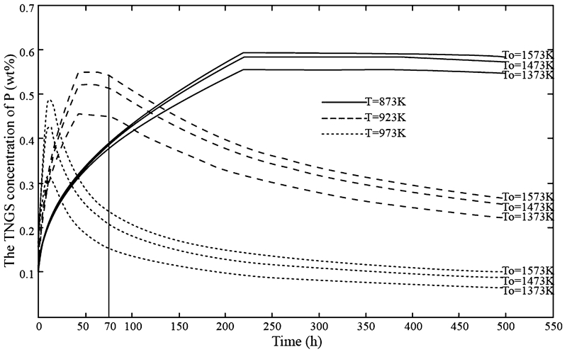
The calculated results for the concentrations of phosphorus TNGS in steels using equations (2)–(5) for aging temperature of 873, 923 and 973 K after quenching from solution temperatures of 1373, 1473 and 1573 K respectively. The vertical line is for the aging time of 70 h
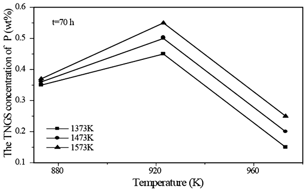
TNGS concentrations of phosphorus in steels aged at 873, 923 and 973 K respectively for 70 h, after quenching from the solution temperature of 1373, 1473 and 1573 K
The relationship between critical time and critical cooling rate
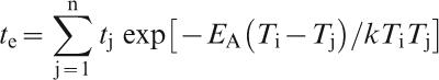
TNGS can also arise during cooling from high temperature. The rate effect of TNGS must be considered, since the segregation occurs over the integrated range of cooling.33,
34 This is another characteristic of TNGS.20 Newtonian cooling was used to calculate the segregation concentration during cooling.33 In order to quantify the effect of continuous cooling on TNGS, the concept of effective time was introduced to produce an approximation.20,
22 A continuous cooling plot of a sample in temperature–time coordinate can be replaced by a corresponding step plot, where each step is formed by horizontal and vertical segments. If a cooling plot from the solution treatment temperature T
i to temperature T
j is replaced by the step plot, which possesses n steps, the effective time t
e, for the entire step plot corresponding to temperature T
i, is obtained by summation20
The rate effect of TNGS must be considered, because the segregation is occurring over the integrated range of cooling. According to equation (6), for any cooling plot (or any cooling rate) in temperature–time coordinate, an effective time at any temperature can be calculated. Thus, there is a cooling rate at which the effective time at a temperature equals the critical time at this temperature. This rate is referred as the critical cooling rate of TNGS.23 If the samples are cooled at the critical cooling rate, a maximum amount of TNGS would be obtained. If the samples were cooled at a slower or faster rate than the critical cooling rate, the amount of TNGS will be lower.23 The existence of critical cooling rate was experimentally demonstrated by Sn segregation in low carbon steel62 – 64 and B segregation in interstitial free steel.65 It was also found that increasing phosphorus concentration in interstitial free steel can increase the critical cooling rate of B TNGS from 10 to 555°C s−1 and thus the critical time of B TNGS in this steel is decreased.65 Accordingly, the critical time will be longer (shorter) if the critical cooling rate is slower (faster). This is an important relationship between critical time and critical cooling rate.
Stress induced non-equilibrium grain boundary segregation
A great deal of engineering practice has confirmed that the degradation of properties, embrittlement, creep, fatigue and brittle fracture can occur in metallic materials during service to produce accidents without any prior indication. The metal is generally at an applied stress below the yield strength and the degradation of mechanical properties occurs. A question arises on the nature of microstructural variation that occurs in polycrystalline materials in the elastic regime and how does this influence the mechanical properties and the performance in service? These have been the vexing challenges to materials scientists and engineers. Recently, it was observed that the primary microstructural variation in polycrystalline materials under an elastic tensile stress was associated with absorption of vacancies at the grain boundaries to produce grain boundary segregation of solutes during grain boundary anelastic relaxation.24 – 26 This kind of segregation is referred to as SNGS.20, 24 On this basis, the equilibrium and kinetic equations of grain boundary segregation under grain boundary anelastic relaxations were established,20,24 – 27 which are used here to clarify the mechanism of ITE.
Critical time
The model of SNGS was first attempted in 2000.25 When a low tensile stress is applied to a grain boundary at a high temperature, the vacancies in the vicinity of the grain boundary absorb at the grain boundaries. Because of the thermal equilibrium between vacancies, solute atoms and vacancy–solute complexes in the bulk, a decrease in vacancy concentration near grain boundaries causes dissociation of complexes into vacancies and solute atoms. Consequently, the concentration gradient of complexes forms and drives complexes to diffuse to grain boundaries, resulting in SNGS of solute. When the equilibrium of anelastic relaxation is obtained at grain boundaries, the absorption of vacancies terminates and the supply of complexes to grain boundaries ends. When the vacancy–solute complexes diffuse to the grain boundary, a concomitant but reverse diffusion of solute atoms away from the boundaries takes place along the solute concentration gradient. At the beginning of this process, the complex diffusion is dominant and decreases with increasing stress aging time because only a certain concentration of vacancies are absorbed into one unit volume of grain boundary for a constant tensile stress. But the reverse diffusion of solute increases with increasing stress aging time. Accordingly, an aging time must exist at which the solute diffusion balances the complex diffusion and at the same time the solute boundary concentration reaches a maximum. This aging time is referred as the critical time of SNGS. The SNGS, in general, disappears as the stress aging time approaches infinity to attain complete equilibrium.24 – 26
In Ref. 25, an equation of critical time for SNGS was formulated, which had the same form as equation (2) of TNGS
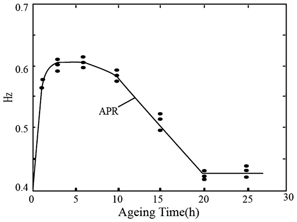
Auger peak height ratio of sulphur grain boundary segregation isotherm with respect to Fe (703 eV) recorded in a low alloy steel under tensile stress at 883 K67
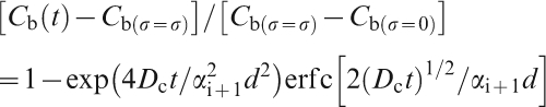
Equilibrium equations
When the equilibrium stress is attained during anelastic relaxation under a constant tensile stress, the absorption of vacancies stops at the grain boundaries and a certain number of vacancies are absorbed in a unit volume of grain boundary. The grain boundary vacancy concentration 


To quantify the grain boundary concentration of solute under tensile stress, the following assumptions are proposed:24,
26 (1) the complex statistically contains one vacancy and one solute atom; (2) nearly all the increase in solute and vacancy concentration in the grain boundary region induced by the tensile stress is produced by the diffusion of complexes to grain boundaries. This is because of faster diffusion of complexes compared to the solute atoms.24,
27 Thus, the maximum concentration of solute under stress equilibrium in the grain boundary region 


It should be mentioned that equations (8) and (9) are valid only for the elastic deformation of grain boundaries because its derivation is based on Hooke’s law. Thus, they cannot be applied to plastic deformation at grain boundaries, for example, to diffusional creep.24
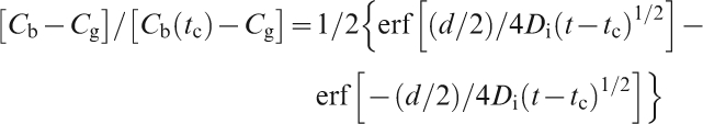
Segregation peak temperature
The equilibrium equation (9) provides a boundary condition to solve the segregation equations of SNGS induced by the tensile stress. For the segregation phase, the stress aging time is shorter than critical time, and the kinetic equation is given by24,
26
Using equations (7) and (9)–(11), the experimental results reported by Shinoda and Nakamura68 for P in steel and by Misra67 for S in steel were simulated20, 24, 26 and are presented in Figs. 8 and 9 respectively. The value of grain boundary concentration at zero time for P in Fig. 8 is about 0·30 at-%20 and for S in Fig. 9 is about 4·8 at-%.24 The simulated results confirm the validity of equations. It can be known from the simulation that the diffusion coefficient of the vacancy–sulphur atom complexes under tensile stress (2·1×10−12 m2 s−1) is larger than that (1·4×10−15 m2 s−1) in the absence of stress76 by about three orders of magnitude. The diffusion coefficient of sulphur, 1·9×10−22 m2 s−1, under tensile stress is smaller (1·24×10−17 m2 s−1), in the absence of stress77 by about five orders of magnitude. Thus, it can be concluded that the tensile stress increases the diffusion coefficient of the vacancy–solute atom complexes and simultaneously decreases that of solute atoms.24, 27 Such an effect is expected to accelerate SNGS.
The critical time in TNGS and SNGS results from the flux of solute atoms diffusing away from the grain boundaries to balance the flux of solute–vacancy complex diffusing to the grain boundaries. Both are the aging time at which the solute concentration at grain boundaries reaches a maximum. Thus, the critical time given by equation (7) for SNGS has an identical form to the critical time equation (2) for TNGS. The critical time for SNGS also decreases (increases) as stress aging temperature increases (decreases). The SNGS concentration depends on how close the stress aging time is to the critical time. When the aging time is close to the critical time, the SNGS concentration is higher, irrespective of whether the material is over- or understress aged.
It is difficult to calculate the kinetic plot with equations (7) and (9)–(11) in the case of SNGS because of the lack of available data in the presence of tensile stress. Therefore, no attempt has been made here to quantify these data. Figure 10 is only a simple schematic. Figure 10a illustrates the variation in concentration of impurity SNGS with stress aging time using equations (7) and (9)–(11). The first vertical line indicates the stress aging time of t 1 hours, which is close to the critical time at temperature T 3. The SNGS concentrations of impurity for aging time of t 1 hours at T 1–T 5 are the concentration of the intersecting points of the vertical line with the kinetic plots, C 1–C 5 respectively. They are presented in Fig. 10b as a function of stress aging temperature. A maximum value (peak) of concentration is C 3 at temperature T 3 for concentrations of C 1, C 2, C 3, C 4 and C 5. It is concluded from Fig. 10 that for such a stress aging process, samples aged in the presence of tensile stress for identical times at various temperature, one aging temperature must exist at which the SNGS concentration of impurity reaches a maximum (peak). The critical time of this aging temperature is equal or close to the stress aging time. This stress aging temperature is called the SNGS peak temperature.
a A schematic diagram showing the variation of concentration of impurity SNGS with stress aging time as a function of temperatures T 1, T 2, T 3, T 4 and T 5. The vertical lines are for the stress aging time of t 1 and t 2 hours respectively. b SNGS concentration of impurity stress aged at temperatures T 1, T 2, T 3, T 4 and T 5, for t 1 and t 2 hours respectively, T 1>T 2>T 3>T 4>T 5
As discussed in the section on ‘Effect of temperature difference’, the temperature difference between the solution temperature and aging temperature is a precondition for TNGS peak temperature to occur. But for grain boundaries in thermal equilibrium, the SNGS peak temperature can still occur, when a tensile stress is applied. Thus, no temperature difference is required for the SNGS peak temperature, as illustrated in Fig. 10a . This is a very important difference between TNGS peak temperature and SNGS peak temperature. This peculiar characteristic is used here to explain important phenomenological features of the ITE.
Movement of segregation peak temperature
From Fig. 10, it may be noted that the SNGS peak temperature is at a higher temperature T 3 for shorter aging time, t 1 and at a lower temperature T 4 (T 3>T 4) for a longer aging time t 2 (t 1<t 2). Thus, it can be concluded that the temperature at which maximum SNGS concentration occurs moves to a lower temperature, when the stress aging time is prolonged at different temperatures. This phenomenon is similar to the movement of TNGS peak temperature. It is called the movement of SNGS peak temperature. It is an inevitable consequence deduced from equations (7) and (9)–(11).
Different strain rates are usually adopted in elevated temperature tensile tests. Decreasing the strain rate prolongs the elastic stress aging time (ESAT) during the elevated temperature tensile test. Thus, it can be deduced from the movement of SNGS peak temperature that decreasing strain rate in the tensile test, moves the SNGS peak to lower temperatures. This is a very important characteristic of SNGS, and plays an important role in clarifying a series of important experimental observations of ITE in the forthcoming section.
Using the characteristics of TNGS and SNGS such as critical time, segregation peak temperature, movement of peak temperature and the effect of temperature difference, different properties in RTE, ICE and ITE can be clarified. This constitutes the focus in the forthcoming section.
Universal mechanism of intergranular embrittlement
When metals or alloys are held at different temperatures after quenching from a higher solution temperature, such as temper treatment, sensitising treatment and isothermal holding at test temperature before stretching, the TNGS of impurities occurs and induces RTE in steels, ICE in stainless steels and ITE in metals or alloys respectively. When metals or alloys are subjected to a tensile stress as in the case of tensile test, the SNGS of impurities occurs during the ESAT and also induces ITE. This is referred to here as the NGS mechanism of intergranular embrittlement. The observations and analysis of such a universal mechanism is reviewed.
Reverse temper embrittlement
RTE in low alloy steels is generally defined as the embrittlement that occurs after heating or slow cooling in the critical temperature range of 350–550°C.1 The common indications of RTE are: a loss of toughness, i.e. shift of ductile to brittle transition temperature (DBTT) to higher temperature, the fracture path is generally along the grain boundaries, and there is grain boundary segregation of impurities. Since its observation in 1883, a number of mechanisms have been proposed. Before the 1950s, it was considered to be induced by grain boundary precipitates. However, the reverse temper embrittlement was subsequently confirmed to occur in samples with no precipitates along the grain boundaries.1,78 – 81 McLean29 and Seah82 proposed that embrittlement was due to EGS of dilute elements. It was believed that the enrichment of some impurities at the grain boundaries reduces the cohesion, causing grain boundary failure. This was termed the EGS model for RTE. However, as pointed out by Hickey and Bulloch,1 the present EGS model does not satisfactorily explain the phenomenological effects of RTE.
Ductility healing effect
In Refs. 20 and 83–85, it was suggested that TNGS of impurities can induce the RTE in steels. It was pointed out that the critical time of impurity TNGS can induce a critical time during the isothermal temper treatment at which a maximum of RTE is obtained. When the isothermal temper time is beyond the critical time, the level of the embrittlement decreases with temper time. This is called ductility healing effect of RTE.
Li et al. 52 studied the kinetics of grain boundary segregation of P in 12Cr1MoV steel. It was confirmed that a peak in P TNGS appears at ∼500 h, indicating that the critical time of P TNGS to be ∼500 h at 540°C. Temper embrittlement in their experiments was characterised by DBTT. The peak of P TNGS corresponds to the maximum value of DBTT and both are at ∼500 h. Li et al. 52 concluded that the critical time of P TNGS induces the maximum value of RTE. After 500 h, the decrease in DBTT confirmed the ductility healing effect.
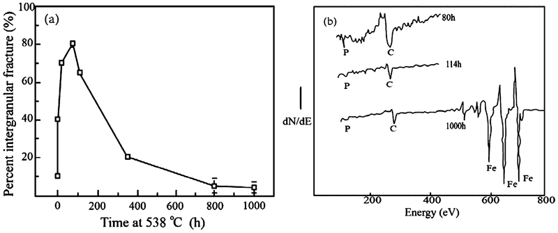
The dynamics of RTE at 538°C in a medium carbon Cr steel was examined by Zhang et al. 86 The observations revealed that a peak in 50% fracture appearance transition temperature occurs at ∼25 h.86 The variation in the percentage of intergranular fracture with tempering time shown in Fig. 11a is in good agreement with the variation of fracture appearance transition temperature.86 The AES measurements demonstrated that after tempering for 80 h, the concentration of P on the intergranular fracture surface gradually decreased with increasing tempering time and almost disappeared at ∼1000 h, as shown in Fig. 11b . This suggested a peak P concentration at grain boundaries at duration less than 80 h. The critical time at 538°C calculated by equation (2) was ∼21 h,86 which meant that the peak of P TNGS and intergranular embrittlement occurred at the hold time of ∼21 h. Thus, the decrease in percentage of intergranular fracture after ∼80 h, as shown in Fig. 11a is representative of the ductility healing effect of RTE, induced by the critical time of P TNGS.
Zheng et al. 60 analysed the experimental results of relationship between grain boundary segregation of antimony and temper embrittlement in titanium doped nickel–chromium steel reported in Ref. 87. The results are summarised in Table 1. It is noted that the peaks of Sb TNGS and RTE occur between 160 and 300 h when the alloy was aged at 480°C. Increasing the aging time from 300 to 8000 h decreased both the concentrations of Sb TNGS and RTE. The peaks of Sb TNGS and RTE occurred between 20 and 100 h, when the alloy was aged at 520°C. Prolonging the aging time from 100 to 8400 h led to decrease in both the concentration of Sb TNGS and RTE. Zheng et al. 60 concluded from the results that the critical time of Sb TNGS induces the peak in RTE and the ductility healing effect of RTE in the Ti doped Ni–Cr steel (Table 1).
From the experiments reported by Li et al.,52 Zhang et al. 86 and Zheng et al.,60 the ductility healing effect of RTE was observed to be consistent with the critical time model of TNGS rather than one that is related to precipitation or EGS.88 It can be concluded that the ductility healing effect of RTE is induced by the critical time of impurity TNGS.
Embrittlement peak temperature
In Powers’ studies,89 nine Mo–W steels were aged for 1000 h at various temperatures after quenching from a higher temperature and the susceptibility of the embrittlement was measured in terms of DBTT, which is based on the Charpy data. An optimum embrittling temperature of around 482°C for all nine steels of different compositions is shown in Fig. 12. The question is why does this optimum embrittling temperature exist at 482°C? Table 2 summarises the calculated critical times for P at various temperatures. It can be seen from Table 2 that it is only at 477°C that the critical time, 1008 h, is the closest to the isothermal aging time, 1000 h, adopted by Powers in his experiments. Thus, a maximum of non-equilibrium segregation level and in embrittlement must be attained at 482°C. For all the specimens at an embrittlement temperature lower than 477°C, the relative critical times increases rapidly and becomes increasingly longer than 1000 h with decreasing temperature. Therefore, the degree of embrittlement is reduced when the isothermal aging time is 1000 h. For all the specimens at temperatures greater than 477°C, the relative critical time decreases rapidly and becomes increasingly shorter than 1000 h with increasing isothermal aging temperature. Thus, the degree of embrittlement also becomes lower because of the desegregation of P when the aging time is 1000 h.83, 84 As a result, the RTE peak temperature at 482°C observed by Powers can be explained clearly by the TNGS peak temperature of P.83
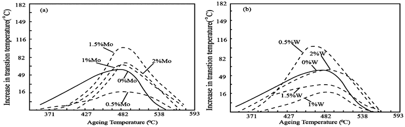
Development of temper embrittlement in a molybdenum steels and b tungsten steels upon aging for 1000 h at various temperatures after quenching89
Calculated critical times of TNGS at various temperatures from equation (2) for phosphorus in steels83
Movement of embrittlement peak temperature
According to the movement of TNGS peak temperature, the temperature at which the RTE peak occurs should move to a higher temperature if the temper times at different temperatures are decreased and shifts to a lower temperature if the tempering time is prolonged. Bush and Siebert’s experimental results90 indicated an embrittlement peak at 454°C for all the specimens aged for 3000 h at different temperatures, and at 510°C for all the specimens aged for 100 h, as shown in Fig. 13.83, 90 These experiments provided the evidence that the movement of TNGS peak temperature can induce the movement of RTE peak temperature.
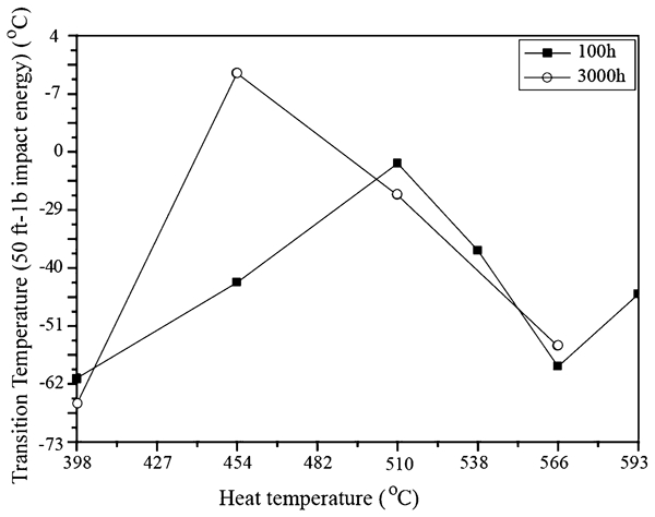
The variation of transition temperature (50 ft-lb impact energy) with tempering temperature for tempering times of 100 and 3000 h respectively after quenching90
Effect of temperature difference on embrittlement
A most important example that confirms the effect of TNGS temperature difference on RTE is the difference between ‘one-step temper embrittlement’ and ‘two-step temper embrittlement’. Historically, the research on RTE can be divided into two regimes. One occurs after a single tempering treatment of the martensite, which is after quenching from the austenitisation temperature, and is called ‘one-step temper embrittlement’ (OSTE). The other occurs when the steel is subjected first to a high temperature tempering of the martensite at about 600–700°C after quenching from the austenitisation temperature and then to an additional isothermal aging treatment between 350–550°C, referred as ‘two-step temper embrittlement’ (TSTE).91 – 93
An aspect that is not yet clear is as to why intercritical heat treatment in the α–γ region, after austenitisation but before tempering, reduces temper embrittlement.91 – 93 This phenomenon in Bush and Siebert’s experiments90 was attributed to the effect of temperature difference in TNGS.83, 84 According to equation (2), the critical time t c for P at 690°C is 1·2 h. It is clear that the tempering time of 5 h at 690°C is large enough to neutralise the P segregation level, which is caused by the first quench from 871°C into an agitated oil bath. Thus, these tempered specimens were considered to be in the toughened state.90 It is concluded in Bush and Siebert’s experiments that the temper embrittlement was caused by water quenching from 690°C. The degree of segregation level induced by water quenching from 690°C for TSTE is significantly lower than that introduced by quenching from austenitisation temperature 871°C directly for OSTE. The underlying difference being the effect of temperature difference of TNGS mentioned in the section on ‘Effect of temperature difference’.83, 84 Thus, TSTE produces a lower degree of temper embrittlement than OSTE.
Capus94 concluded that RTE is observed in steels containing Cr as an alloying element and phosphorus as an impurity such that picric acid selectively attacks the prior austenite grain boundaries. Therefore, ICE is also a kind of reverse temper embrittlement.
Intergranular corrosion embrittlement
Austenitic stainless steels are susceptible to ICE.95 – 97 Especially, ICE in the heat affected zone of welds in boiling water environment has been a continuing problem. ICE is suggested to occur primarily as a consequence of weld induced sensitisation of heat affected zones in materials with high carbon content (≥0·2 wt-%) because of Cr depletion adjacent to the Cr rich carbides (M23C6) at grain boundaries.98, 99 However, ICE also occurred in Ti or Nb stabilised steels that did not have Cr depletion because of the preferred nucleation of TiC or NbC instead of M23C6 precipitates. This behaviour was attributed to impurity segregation to the grain boundary. In fact, P and S have been argued to enhance ICE in certain environments and confirmed by examining their presence at the grain boundaries by Auger electron spectroscopy (AES).100 – 103
Ductility healing effect
A ductility healing of ICE occurs when the material is treated for a prolonged time at sensitising temperatures.9 The ICE in a commercial purity 304 austenitic stainless steel was examined by relating the grain boundary composition to the corrosion properties by Joshi and Stein.4 The commercial purity 304 austenitic stainless steel was given a 2 h treatment at 1050°C in argon atmosphere and water quenched. This condition is termed ‘non-sensitised’. Subsequent treatments were given as follows: (1) non-sensitised+2 h at 650°C followed by water quench; (2) non-sensitised+72 h at 650°C followed by water quench. The AES intergranular peak height of S with respect to Fe and the results of corrosion tests are presented in Table 3.
The AES results and corrosion test in boiling nitric dichromate* solution of 304 stainless steels4
*Weight loss rate determined at the end of 14 corrosion tests in nitric dichromate solution.
It can be seen from Table 3 that the AES S/Fe ratio is 1·230 for the non-sensitised sample, while the S/Fe ratio decreases from 1·230 for the non-sensitised sample to 0·920 and 0·850 for the non-sensitised+2 h and non-sensitised+72 h at 650°C respectively. The grain boundary concentration of S decreases as the sensitising time is increased at 650°C. The corresponding corrosion rate also decreases from 2·25 mg cm−2 h−1 for the non-sensitised sample to 0·87 mg cm−2 h−1 for the non-sensitised+72 h at 650°C sample. For the non-sensitised+2 h sample, the corresponding corrosion rate should have decreased from 2·25 mg cm−2 h−1, but it is at 2·93 mg cm−2 h−1. This may be a poorly measured data. The question arises as to why both the grain boundary concentration of S and the corrosion rate decrease on prolonging the sensitising time at 650°C. The treatment (1), water quenching from 1050°C, is a continuous cooling, which is equal to non-sensitised+0 h at 650°C. The discussion in the section on ‘The relationship between critical time and critical cooling rate’, the effect of diffusion of elements during continuous cooling is the same as that of the sample held for an effective time at a constant temperature. It is therefore suggested that the segregation level in samples quenched from 1050°C in water is the same as the segregation levels for the sample aged at 650°C for an effective time t e after a rapid quenching from 1050°C. Thus, the segregation levels for samples treated as treatments (2) and (3) equate with the segregation levels for samples aged at 650°C for t e+2 h and t e+72 h respectively. According to the critical time of TNGS, it is reasonable to consider that t e is significantly closer to the critical time of S at 650°C than t e+2 h and t e+72 h. This means that the sensitising time t e+2 h and t e+72 h are longer than the critical time of S at 650°C. Thus, the TNGS of S decreases from 1·230 through 0·920 to 0·850 with increasing sensitising time from t e+0 h, through t e+2 h to t e+72 h at 650°C. The decrease in TNGS concentration of S tends to decrease the corrosion rate from 2·25 through 2·93 to 0·87 mg cm−2 h−1 on prolonging the sensitising time at 650°C, thus producing ductility healing effect of ICE. Joshi and Stein4 also concluded from the experimental results that corrosion properties of 304 stainless steel are related to S segregation and S strongly accelerates the corrosion when it is segregated to grain boundaries, while no such relationship was observed with Cr depletion. Thus, Cr depletion, although present, is not the factor that controls ICE.4
Another comprehensive examination of ICE in a commercial 304 austenitic stainless steel (0·038 wt-%C) was made by Stickler and Vinckier, in which specimens were subjected to a wide range of sensitising heat treatments.9 Their classical and systematic experimental results are presented in Figs. 14–16. The 304 steel was solution treated at 1260°C for 1·5 h and water quenched. Samples were then held at temperatures between 899 and 482°C respectively for different times in the range of 0·15–1500 h. The susceptibility to corrosion attack for the heat treated samples was tested by exposing polished specimens for duration of 45 or 450 h to the Strauss solution. The degree of ICE was determined by the extent of cracking of the specimens after a 180° bend in a three-point bend test carried out at room temperature. It was observed that after 450 h exposure to Strauss solution, a corrosion embrittlement peak between no cracking and slight cracking (0–1 in Fig. 14) appeared on sensitisation from 1·5 to 150 h, during sensitisation at 816°C. When the sensitising time at 816°C was shorter than 1·5 h, the corrosion embrittlement decreased to no cracking (0 in Fig. 14). When the sensitising time was larger than 150 h, the corrosion embrittlement decreases to no cracking (0 in Fig. 14). Moreover, a corrosion embrittlement peak between medium cracking and severe cracking (1–2 and 2–3 in Fig. 14) appeared at sensitising time from 15 to 150 h during sensitising at 732°C. When the sensitising time at 732°C was less than 15 h, the corrosion embrittlement decreased and was between no cracking and slight cracking (0–1 in Fig. 14). When the sensitising time was larger than 150 h, the corrosion embrittlement decreased to medium cracking (2 in Fig. 14).
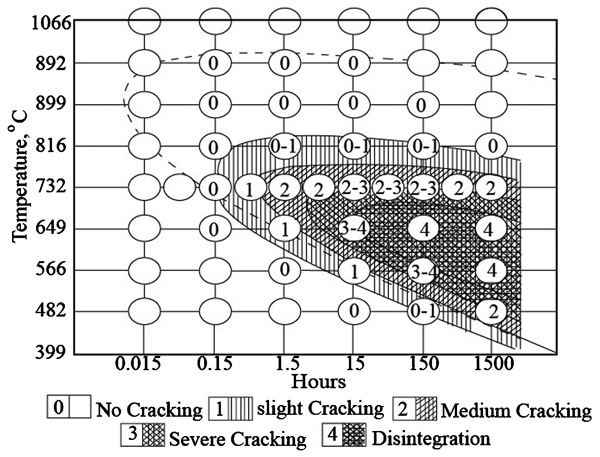
Embrittlement of sensitised 304 stainless steel after a 450 h exposure to Strauss solution9
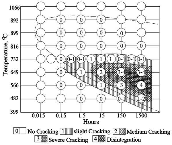
Embrittlement of sensitised 304 stainless steel after a 45 h exposure to Strauss solution9
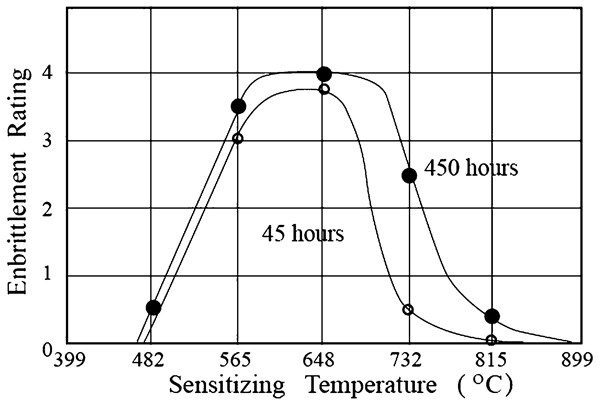
Embrittlement of 304 stainless steel sensitised for 150 h at different temperatures after 45 and 450 h exposure to Strauss solution9
It is seen from Fig. 15 that after a 45 h exposure to Strauss solution, a corrosion embrittlement peak indicated by slight cracking (1 in Fig. 15) appeared at the sensitising time around 15 h on sensitising at 732°C. When sensitising time is less than 1·5 h, the corrosion embrittlement decreases and lies between no cracking and slight cracking (0–1 in Fig. 15). When sensitising time is larger than 150 h, the corrosion embrittlement decreases to no cracking and slight cracking (0–1 in Fig. 15). Table 4 lists the critical time of S TNGS in the 304 stainless steel calculated by equation (2).104 It is evident that the critical time of S is about 3·5 h at 815°C and 20 h at 732°C respectively. Both correspond to the sensitising time of corrosion embrittlement peaks at 815 and 732°C respectively. Thus, the ductility healing effect of ICE with prolonged sensitising time shown in Figs. 14 and 15 is induced by the critical time of S TNGS.104, 105
The critical time of sulphur calculated at different aging temperatures104
Embrittlement peak temperature
It may be noted from Fig. 14 that after a 450 h exposure to Strauss solution, a corrosion embrittlement peak indicated by medium cracking (2 in Fig. 14) occurs at the sensitising temperature of 732°C in all the samples sensitised for 1·5 h at different temperatures. When the sensitising temperature decreases from 649 to 566°C, the corrosion embrittlement decreases and lies between slight cracking and no cracking (1–0 in Fig. 14). When sensitising temperature increases to 816°C, the corrosion embrittlement also decreases and lies between no cracking and slight cracking (0–1 in Fig. 14). A corrosion embrittlement peak between medium cracking, severe cracking and disintegration (2–3 and 3–4 in Fig. 14) occurs at sensitisation temperatures between 649 and 732°C for all the samples sensitised for 15 h at different temperatures. When the sensitisation temperature decreases from 565 to 482°C, the corrosion embrittlement decreases to between slight cracking and no cracking (0–1 in Fig. 14). When sensitisation temperature increases to 816°C, the corrosion embrittlement also decreases to between no cracking and slight cracking (0–1 in Fig. 14).
Moreover, from Fig. 15, it is noted that after a 45 h exposure to Strauss solution, a corrosion embrittlement peak between severe cracking and disintegration (3–4 and 3 in Fig. 15) occurs at the sensitisation temperature between 649 and 566°C for samples sensitised for 150 h at various temperatures. When sensitising temperature decreases to 482°C, the corrosion embrittlement decreases to between no cracking and slight cracking (0–1 in Fig. 15). When sensitising temperature increases in the range of 732 and 816°C, the corrosion embrittlement also decreases to between no cracking and slight cracking (0–1 in Fig. 15). A corrosion embrittlement peak indicated by disintegration (4 in Fig. 15) occurs at the sensitisation temperature of 566°C in samples sensitised for 1500 h at different temperatures. When sensitising temperature decreases to 482°C, the corrosion embrittlement decreases to between medium cracking and slight cracking (1–2 in Fig. 15). When sensitising temperature increases to 816°C, the corrosion embrittlement decreases to no cracking (0 in Fig. 15).
The critical times of S TNGS calculated by equation (2)104 are summarised in Table 4 for the 304 stainless steel aged at different temperatures after quenching from a solution temperature of 1260°C, which is the same as Sticker and Vinckier’s heat treatment cycles.9 The critical time of 20 h at 732°C is the closest to the sensitising time of 15 h. Thus, a corrosion embrittlement peak occurs at the sensitisation temperature between 732 and 649°C for all the samples sensitised for 15 h at different temperatures. The critical time of 150 h at 649°C is equal to the sensitising time of 150 h. Therefore, a corrosion embrittlement peak occurs at the sensitising temperature between 649 and 565°C for samples sensitised for 150 h at different temperatures. Similarly, the critical time of 1690 h at 565°C is close to the sensitising time of 1500 h. Therefore, a corrosion embrittlement peak occurs at the sensitising temperature of 565°C for samples sensitised for 1500 h at different temperatures. Based on these observations, Wang et al. 104 concluded that the ICE peaks in Stickler and Vinckier’s experiments are induced by the TNGS peak temperature of S.
Briant and Andresen103 studied grain boundary segregation in austenitic stainless steels and its effect on intergranular stress corrosion cracking. Table 5 lists the composition of the alloys for heats E, F, G, H and I used in their study. All steels were solution treated at 1100°C for 1 h and water quenched. They were then aged for times up to 100 h at temperatures between 500 and 700°C. Subsequently, they were strained to failure at an extension rate of 3×10⁻⁷ s−1. The corrosion tests were carried out in N deaerated 0·005M sulphuric acid (pH 2·5) at 288°C. The results of stress corrosion cracking test and the grain boundary segregation of sulphur measurements are summarised graphically in Figs. 17 and 18 respectively.
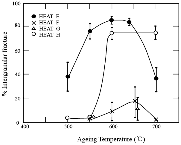
The percentage of intergranular stress corrosion cracking plotted as a function of the aging temperature for samples of heat E, F, G and H. The samples were aged at each of the temperatures for 100 h103
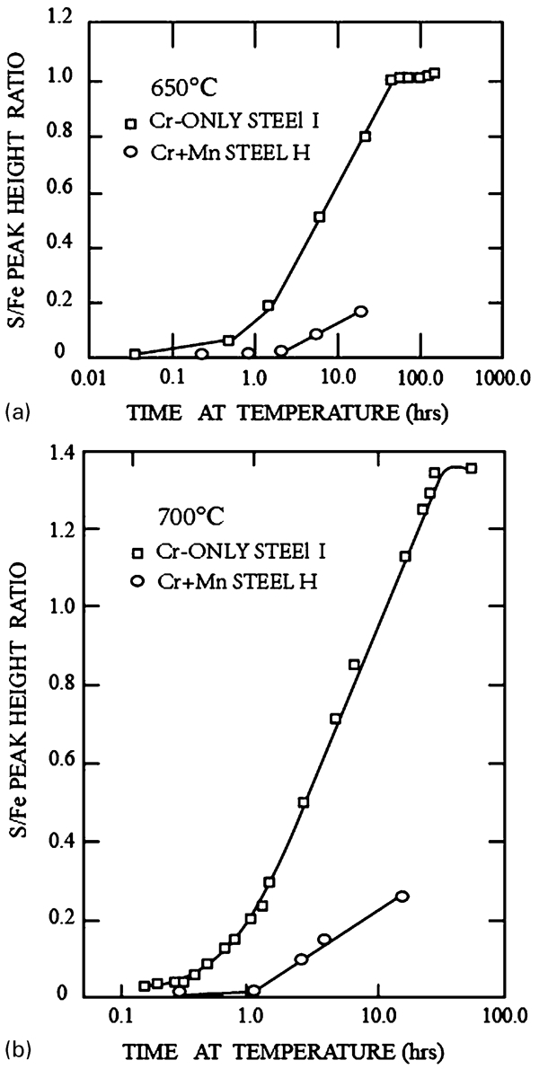
The sulphur to iron Auger peak height ratio plotted as a function of heating time. The temperature were a 650°C and b 700°C. Data were obtained by surface heating103
Chemical compositions/wt-%103
From Fig. 17, it can be seen that the maximum percentage of intergranular stress corrosion cracking occurs between 600 and 650°C for heat E and at 650°C for heat F. Included in the heat treatment cycles for these two heats is one that is similar to that given in Fig. 3b , namely, identical aging time at different temperatures after quenching from a higher temperature. Figure 18 shows that S segregation for heat I is maximum at about 100 and 50 h for temperatures of 650 and 700°C respectively, suggesting that the critical time for TNGS of S is around these times for these temperatures corresponding to the maximum percentage of intergranular corrosion, as shown in Fig. 17.
The critical times at 550 and 500°C are longer than 100 h, so that at 100 h, the concentration of S on the basis of the TNGS theory will be lower at these temperatures leading to reduced cracking, as presented in Fig. 17. The critical time at 700°C is ∼50 h shorter than 100 h, such that at 100 h, the concentration of S according to TNGS theory is lower at this temperature, leading to reduced cracking (Fig. 17). Accordingly, intergranular stress corrosion cracking peaks shown in Fig. 17 for heats E and F are induced by the peak temperature of S TNGS.
Briant and Andresen103 used the segregation data to interpret the stress corrosion cracking results in Fig. 17 and concluded that S segregation enhances intergranular corrosion at slow strain rate tests. In order to explain the decrease in stress corrosion cracking at 700°C in heat E as shown in Fig. 17, they suggested that it was due to the presence of high P content in the steel and that the P segregation competed with S segregation leading to a decreased S concentration at the boundaries.103 However, their P/Fe peak height ratios (see Fig. 1b in Ref. 103) indicated that P segregation is significantly greater at 600 and 650°C compared to that at 500 and 550°C. According to Briant and Andresen, this should have resulted in a decreased S level at the boundaries and reduced stress corrosion cracking and this is clearly not the case, as shown in Fig. 17.
Nevertheless, it must be considered why intergranular stress corrosion cracking and S segregation for heat H does not decrease at 700°C as presented in Figs. 17 and 18. This steel does not contain P (Table 5). It is stated in the section on ‘The relationship between critical time and critical cooling rate’ that the results of alpha-particle track etching65 suggest that the existence of P increases the critical cooling rate of B TNGS and decreases the critical time. As a result, the absence of P will prolong the critical time of solute TNGS. In this case, it is proposed that the critical time of S TNGS is prolonged to greater than 100 h at 700°C due to the absence of P in heat H.
Movement of embrittlement peak temperature
In Fig. 14, for the samples sensitised at different temperatures after quenching from 1260°C and 450 h exposure to Strauss solution, a peak of corrosion embrittlement is at 732°C after sensitisation for 1·5 h. The peak is between 649 and 732°C sensitised for 15 h. The peak moves to 649°C sensitised for 150 h and lies between 649 and 566°C sensitised for 1500 h.
In Fig. 15, for the samples sensitised at different temperatures after quenching from 1260°C and 45 h exposure to Strauss solution, a peak of corrosion embrittlement occurs between 649 and 732°C on sensitisation for 1·5 h. The peak is at 649°C sensitised for 15 h, between 566 and 649°C sensitised for 150 h, and 566°C sensitised for 1500 h.
It is clear that the temperature of embrittlement peak moves from a higher temperature 815°C to a lower 566°C, when the sensitising time is increased from 1·5 to 1500 h. The phenomena can not be explained by McLean’s EGS theory and mechanism of intergranular phase transformation, including the Cr depletion. As shown in Table 4, the critical time of S TNGS increases from 3·5 to 1690 h when sensitising temperature decreases from 815 to 566°C. Because the sensitising time of 15 h is close to the critical time of 20 h at 732°C, the peak of embrittlement appears at 732°C for samples aged for 15 h. The sensitising time of 150 h is equal to the critical time of 150 h at 649°C, the peak appears at 649°C. The sensitising time of 1500 h is close to the critical time of 1690 h at 566°C, the peak embrittlement appears at 566°C. Therefore, the movement of ICE peak in Stickler and Vinckier’s experiments is induced by the movement of TNGS peak temperature.
Effect of temperature difference on embrittlement
Aust et al. 105 investigated the corrosion rates of austenitic type 304 stainless steel for different heat treatment conditions. The solution treated material was heat treated for 2 h at 1060°C and water quenched. The stabilised material was solution treated for 2 h at 1060°C and water quenched, stabilisation annealed for 2 h at 900°C and quenched, plus an additional anneal of 100 h at 200°C and quenched. As shown in Fig. 19, the corrosion rate for the linear part of the plot (curve a) is ∼7 mg cm−1 h−1 and that of plot (curve b) is about 4·7 mg cm−1 h−1, corresponding to a 33% decrease in the corrosion rate of the stabilised material compared to the solution treated material. According to the critical time equation (2) of TNGS, the stabilisation time of 2 h at 900°C is large enough to neutralise the segregation level of S and P, for the stabilised material, which is caused by quenching from 1060°C. Thus, Aust’s question demonstrated that the water quenching from 900°C caused impurity segregation lower than that arising from direct quenching from the austenitisation temperature of 1060°C. Therefore, the stabilised material had a lower corrosion rate than the solution treated material. Hence, the difference in the corrosion rates between the stabilised material and the solution treated material is induced by the TNGS temperature difference. This is similar to that between TSTE and OSTE of RTE in the section on ‘Effect of temperature difference on embrittlement’.
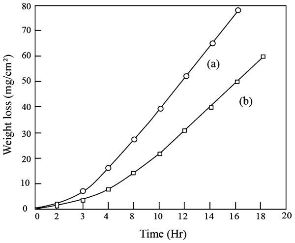
Corrosion of type 304 stainless steel after a 2 h at 1060°C, water quenched and b the same as a plus 2 h at 900°C, quenched, plus 100 h at 200°C, quenched (test solution 5 N HNO3+4 g L−1 Cr+6)105
Aust et al. 105 proposed that intergranular corrosion of the austenitic type 304 stainless steel in an aqueous environment is associated with grain boundary segregation of solute impurities. Aust et al. 105 also observed a significant grain boundary hardening in the solution treated commercial Type 304 stainless steel, which is indicative of a type of solute segregation. However, when high purity stainless steels were prepared, there was no excess grain boundary hardening and no evidence of intergranular corrosion.106 This type of solute segregation was later called TNGS by Aust.57
The Cr depletion theory is one of the earliest and widely accepted for explaining the corrosion rate of stainless steel. According to this theory, precipitation of Cr rich carbides (M23C6) occurs along the grain boundaries when the steel is sensitised, resulting in a depleted region of Cr adjacent to the carbides. The lower Cr content was proposed to be the reason for poor corrosion resistance.103 The stabilised material in Fig. 19 must have more Cr rich carbides and higher corrosion rate than the solution treated material. This is contrary to the experimental results. Furthermore, the Cr depletion theory is supported by the corrosion tests conducted in weakly oxidising solution (Strauss tests) but not supported by Huey test conditions. It was already shown that high purity alloys are immune to corrosion when tested in Huey solution. Thus, it appears that chromium depletion theory is inadequate to explain the observations.106
Intermediate temperature embrittlement
An examination of the published record of high and low temperature tensile properties of a number of metals and alloys suggests that the ITE is a common property of nearly all metals that are highly ductile. A ductility trough in the intermediate temperature range from 0·5T m to 0·8T m with an intergranular fracture mode is called ITE or intermediate temperature ductility loss.107, 108 In the case of Cu alloys, one of the earliest in-depth studies was conducted by the Admiralty at the Portsmouth Dockyard in 1877. Cu and its alloys exhibited a severe reduction in ductility between about 300 and 600°C.109 Later on, similar observations were made in Ti, Al, Ni base alloys, Fe base alloys, Co base alloys, intermetallic compound and Al–Mg alloys.110 – 123 A similar effect appears in high melting and low melting metals including molybdenum,124 tantalum,125 vanadium126 and the lead–tin alloys.120 The fracture of ITE is frequently reported to be intergranular.110 One of the problems specific to the continuous casting of steel is transverse cracking, which is induced by the ITE of steel, referred to here as hot ductility loss.117, 118 The ITE can also induce ductility dip cracking in welds of metals and alloys.110, 111 It is most often quantified in terms of tensile data as a function of temperature. It appears as a sharp decrease in both the tensile elongation to failure and the RA over a limited temperature range. Other tests also reveal the effect, such as minimum ductility appearing in impact absorption tests126, 127 and hot torsion tests.128
Owing to the fact that the ITE is a universal phenomenon in metals and alloys, a universal mechanism needs to be proposed that is suitable for the ITE of metals and alloys. In 1912, Bengough used a concept of equicohesive temperature to explain ITE.129 In 1961, this theory was found to be incorrect.107 Nowadays, the proposed mechanisms are related to the special properties such as ferrite nucleation at austenite grain boundaries in steels117 and precipitate mechanism in alloys. It is clear that the ferrite mechanism cannot account for the ITE of austenitic steels and the precipitate mechanism cannot clarify those of metals and alloys that have no precipitates at grain boundaries.113 – 118 Zheng et al. 120 have summarised a number of proposed explanations for ITE of metals and alloys that include intergranular precipitates,130, 131 grain boundary shearing or sliding,132, 133 gas phase embrittlement,134 decohesion of glide plane,19 dynamic strain aging117, 135 and grain boundary segregation.136 According to the explanations to account for ITE, it concluded that there is no satisfactory explanation that describes a complete understanding of ITE. From a systematic evaluation, the mechanism of NGS is likely to provide a generally accepted explanation for ITE. Chihiro et al. 10 with AES analysis showed that more intensive embrittlement is observed at higher solution treatment temperature and that precipitates are not observed in carbon steels. The embrittlement is enhanced with increase in solution treatment temperature; it is because of the increase of sulphur segregation to grain boundaries. Furthermore, since the sulphur segregation disappeared by lowering the cooling rate, ductility was recovered.10 These experimental results imply that the segregation of sulphur here has the characteristic of NGS, which produces embrittlement at grain boundaries. The mechanism of intergranular precipitates for ITE, such as thin film of deformation induced ferrite and dynamic recrystallisation117, 118, 137 may enhance the ITE in steels, which form ferrite during deformation. But it is not a universal mechanism for all metals and alloys. A number of experimental results on ITE cannot be clarified by this mechanism. Although a great deal is known about the phenomenological effects of ITE, and there has been a continuous effort to explain the effects for nearly 100 years, however, we do not have a satisfactory and universal mechanism of ITE for metals and alloys.
The condition of metallic materials for elevated temperature tensile tests is generally in the as cast or solution treated state. According to the standard test methods for elevated temperature tensile tests of metallic materials,12 the hold time at test temperatures before the start of tensile test should not be less than 20 min. Therefore, the tensile tested materials experience a certain time at different test temperatures after cooling from a higher temperature before the test, and go through the same heat treatment cycle as shown in Fig. 3b . Thus, the TNGS peak temperature of impurity would be present in the tensile tests. Also, in the elevated temperature tensile tests of metallic materials,12 a constant strain rate is maintained. Duration of tensile test is defined as the time from the application of the stress until fracture, which includes ESAT and plastic stage. The constant strain rate will induce a constant ESAT at the test temperatures. In this case, the SNGS peak temperature of impurity as shown in Fig. 10b occurs during ESAT in the elevated temperature tensile test, especially at a lower strain rate. Both TNGS and SNGS peak temperatures are known to produce embrittlement peak (ductility trough) during elevated temperature tensile test. When the strain rate is decreased for these tests, the ESAT increases and the SNGS peak temperature of impurity and the relative ductility trough shifts a lower temperature. Thus, the effect of TNGS and SNGS of impurities on the mechanical property is a universal mechanism for ITE in metals and alloys. Its evidence is presented the following sections.
Ductility healing effect
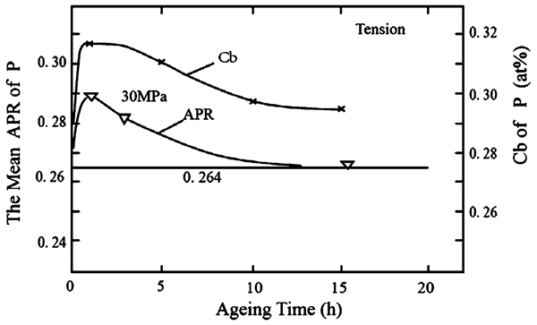
In Wang et al.’s tensile tests of Ni–Cr–Fe alloy,40, 56 the hold time at the test temperature before the start of tensile test was 20 min after specimens were homogenised at 1180°C for 45 min and water quenched. Figure 20a displays the results of their tensile tests and shows an evident ITE being between 300 and 700°C. A maximum embrittlement (minimum of RA) occurs at ∼500°C. Wang et al. 40 40,56 also measured the variation in RA and grain boundary concentration of S with aging time at 500°C, as shown in Fig. 20b . RA increases continuously with aging time from 20 min to 100 h. The S concentration at grain boundaries increases up to 20 min, then decreases continuously with aging time from 20 min to 100 h. A concentration peak appears at ∼20 min, indicating that the critical time of S TNGS at 500°C is ∼20 min. Thus, the decrease in grain boundary embrittlement with aging time after 20 min in Fig. 20b is a ductility healing effect of ITE and is induced by the critical time of S TNGS.
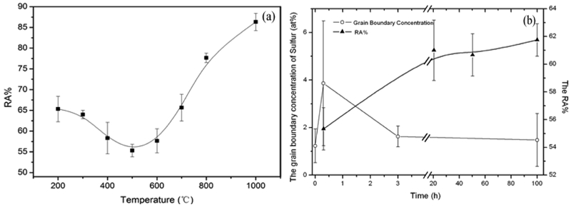
a Reduction in area (RA/%) plotted as a function of test temperature for Ni–Cr–Fe alloy. The error bars represent ±1σ standard deviation. b The variation of sulphur grain boundary concentration and the RA with aging time at 500°C for Ni–Cr–Fe alloy. The error bars represent ±σ standard deviation40, 56
Kizu and Urabe138 investigated the hot ductility of low Mn mild steels containing Mn (0·06 wt-%) and different concentrations of S. Specimens were heated at the rate of 5 K s−1 up to 1573 K (solution temperature, reheating temperature, RHT), and held for 600 s in vacuum. Subsequently, the specimens were cooled at a constant rate of 30 K s−1 in nitrogen atmosphere to tensile test temperatures (TT) in the range of 1023–1473 K. After holding time of 300 s at each tensile temperature, the specimens were deformed at a strain rate of 22 s−1 until fracture. After the fracture, the samples were immediately quenched to room temperature in helium gas. The influence of tensile test temperature and S content on RA for 0·06 wt-%Mn steels is presented in Fig. 21.138 As tensile test temperature decreases, RA decreases until 1223 K and then increases dramatically at 1073 K. It is clear that a minimum in RA occurs at the tensile test temperature 1223 K. Figure 21 shows that decreasing the content of S reduces the width and depth of ITE trough. Just as shown in Ref. 16 that high purity iron with S less than 2 ppm exhibited an excellent hot ductility at all test temperatures between 673 and 1173 K. Addition of 5 ppm S led to hot ductility drop between 873 and 937 K. Further increase in the S content in the high purity iron decreased RA, and widened the temperature range of ITE.16 These results show that S segregation at grain boundaries plays a dominant role in regard to ITE.
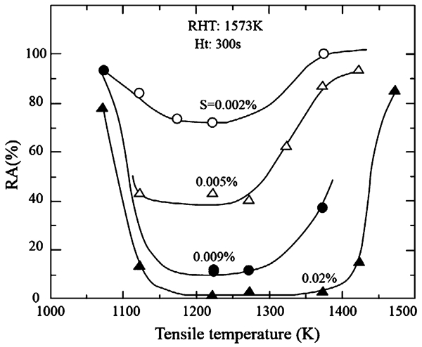
The influence in tensile test temperature and sulphur content on RA at reheating temperature of 1573 K for holding time of 300 s (concentration in wt-%)138
Furthermore, the influence of holding time at the tensile test temperature on hot ductility was also investigated and the results are presented in Fig. 22.138 The RHT and TT are 1573 and 1223 K respectively in Fig. 22. When the holding time before tensile test is extended from 300 to 1800 s at 1223 K, RA increases significantly from 20% to 70%.138 From Figs. 21 and 22, it can be suggested that the critical time of S in this steel is ∼300 s at 1223 K. The hold time between 300 and 1800 s at 1223 K is longer than the critical time at 1223 K. Thus, desegregation of S occurs, inducing TNGS to decrease and the RA to increase. Clearly, Fig. 22 shows typical ductility healing of ITE induced by the critical time of S TNGS in the steel. It should be noted that such an effect can never be clarified by the transformation from austenite to ferrite and dynamic recrystallisation.117
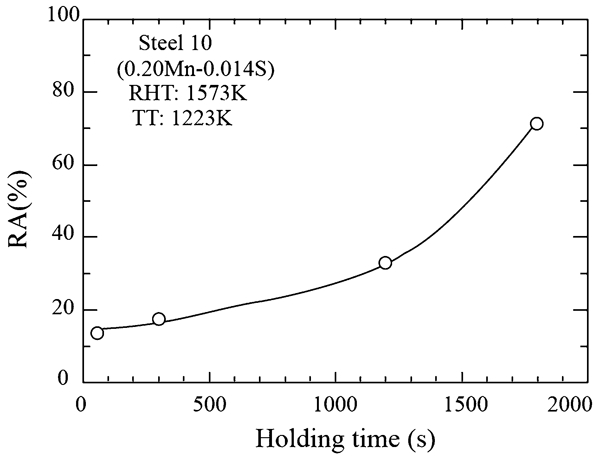
Influence of holding time on RA. Reheating temperature and tensile temperature are 1573 and 1223 K respectively138
The ductility healing effect of ITE in a low carbon steel austenite was also demonstrated by Yasumoto et al.
139 In Yasumoto et al.’s experiment, after holding for 3 min at the solution temperatures in the range of 1373–1623 K, the specimens were cooled at constant cooling rates in the range 0·5–20 K s−1 to tensile deformation temperature in the range of 973–1473 K. After holding for 1 min at the deformation temperature, the specimens were pulled at constant crosshead speeds in the range 0·01–2·3 s−1 until final fracture. A ductility trough emerged between 1100 and 1325 K, as shown in Fig. 23a
.139 It is seen from Fig. 23b
that before the commencement of tensile test, increasing the hold time at temperatures of 1123 and 1323 K where ductility minimum occurred, the ductility is considerably restored. From these results, it can be inferred that the critical time of S TNGS between 1123 and 1323 K is ∼1 min. Increase in the isothermal holding time to more than 1 min at these temperatures led to desegregation of S and to decrease in TNGS of S and increase RA. Predeformation to 20% RA at 
a Variation in reduction of area to failure (RA) with temperature of deformation in tensile test and solution treatment temperature (STT);
The ductility healing effect of ITE has been confirmed by He et al. 19 The specimens of M963 superalloy were solution treated for 4 h at 1210°C, followed by air cooling. The tensile tests were conducted in air in the temperature range of 20–1100°C, when minimum elongation appeared at 800°C. But when the specimens were aged for 16 h at ∼850°C after the solution treatment at 1210°C, the elongation minimum disappeared at 800°C and at other temperatures.19 Obviously, these observations cannot be explained by the EGS theory. According to EGS theory, extending the aging time at ∼800°C is expected to increase the EGS concentration (and not decrease); thereby, the embrittlement should increase and not decrease. Prolonging aging time at the temperature corresponding to minimum elongation to 16 h makes aging time beyond the critical time of impurity TNGS at ∼800°C to decrease segregation concentration of the impurity elements and to eliminate the elongation minimum at 800°C. Such a healing effect of ITE can be explained by the critical time of TNGS of impurity.
Ductility trough induced by thermally induced segregation
The tensile tested materials usually undergo the same heat treatment cycle as shown in Fig. 3b Hence, the TNGS peak temperature of impurity occurs during the holding time at test temperatures before tensile test and induces ductility trough.11, 83 Such a ductility trough induced by TNGS was experimentally shown by Wang et al. 40 40,56 by comparing the result of elevated temperature tensile tests in Fig. 20a of this review to the grain boundary concentration of S in Fig. 24 for the Ni–Cr–Fe alloy. The alloy was aged for 20 min at different temperatures after quenching from 1180°C and then the concentration of S at grain boundaries was measured by AES and is presented in Fig. 24. It is seen from Figs. 20a and 24 that the maximum in the grain boundary concentration of S corresponds to the maximum of ITE at 500°C. As indicated above, Fig. 20b shows that the critical time of sulphur TNGS at 500°C is ∼20 min, which is consistent with the TNGS peak temperature of 500°C presented in Fig. 24. Table 6 shows the calculated critical times at different aging temperatures using equation (2).40, 56 From Figs. 20 and 24 and Table 6, it may be noted that when the test temperatures are less than 500°C, the grain boundary concentration of S and the degree of embrittlement of the alloy decrease with decreasing test temperature because the critical times are longer than 20 min. When the test temperatures are higher than 500°C, the grain boundary concentration of S and the embrittlement also decreases with increasing test temperature because the critical times are less than 20 min. Thus, the ductility trough of ITE in Fig. 20a is induced by TNGS peak temperature of S.
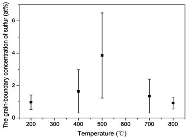
Cortial et al. 140 studied the effect of industrial heat treatment on the mechanical characteristics of weld alloy 625. The weld metal 625 was heat treated as follows: heating in 50°C increment/h, 8 h hold time at the selected temperatures (600, 650, 700, 750, 850, 950 and 1000°C) cooling in air at the cooling rate of 900°C h−1. The EL and RA were determined at 20°C with the major axis parallel to the welding direction: the Charpy V-notch impact strength tests at +20°C with major axis perpendicular to the welding direction and the notch perpendicular to the free surface. The results are presented in Fig. 25a for EL and RA (%) and in Fig. 25b for impact strength. The heat treatments have a similar heat cycle to that shown in Fig. 3b of this review, i.e. hold time of 8 h at different heat treatment temperatures after cooling from the welding temperature. It can be speculated from the minima of EL and RA and the minimum impact strength at 850°C that a critical time of TNGS of an impurity in this alloy is ∼8 h at 850°C and consequently induces a TNGS peak. This observation is interesting from the viewpoint that minima in EL and RA in tensile tests and the minima in impact strength occur at the identical temperature of 850°C. As mentioned above, the TNGS of impurity can induce ITE during the holding time before tensile deformation and SNGS of impurity can also induce ITE during the time stress is applied in the tensile test. The fact that the minima in EL and RA are at the same temperature as the minima in impact strength indicates that there is no effect on time for which the stress is applied on the mechanical behaviour in tensile test. The ESAT in tensile test is too short as compared to the hold time of 8 h at the experimental temperature. Accordingly, the ITE of weld alloy 625 is induced by the TNGS and not SNGS. This result cannot be clarified by the mechanism of dynamic recrystallisation because impact tests have no ESAT that is adequate to produce dynamic recrystallisation.
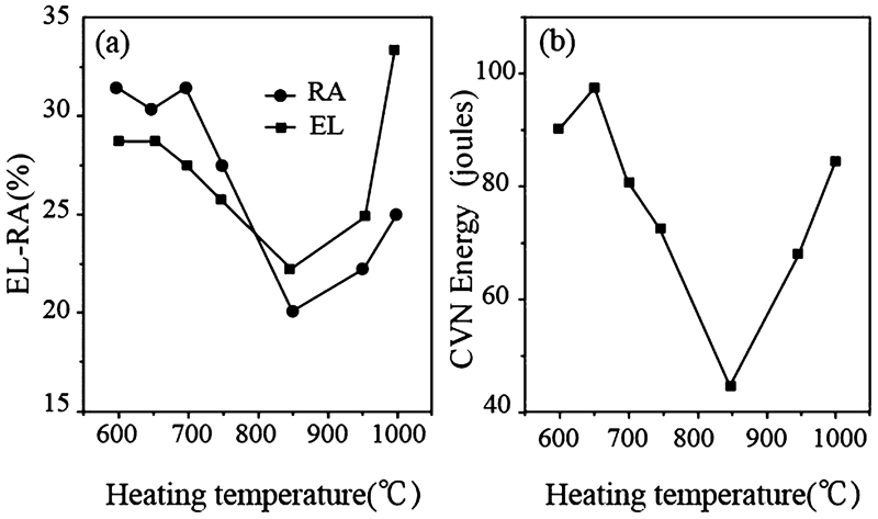
Mechanical properties as a function of heat treatment: a ductility and b impact strength140
Powers89 reported the experimental results in Fig. 12 as the RTE data. In fact, the data also demonstrate the ITE of steels. This is because the grain boundary embrittlement occurs at an intermediate temperature range and moreover, the Powers’s heat treatment cycle is identical to that of the elevated temperature tension tests. The differences between them are only in the duration at each temperature and the method used to measure the intergranular embrittlement. Given that the ITE in Powers’s experiment is determined via impact tests, it is not related to dynamic recrystallisation. Thus, the dynamic recrystallisation in some tests, although present, is not the factor controlling ITE.
In reality, the ductility troughs of sulphur containing low manganese mild steel presented in Fig. 21 138 and of low carbon austenite steel presented in Fig. 23a 139 were also induced by TNGS. High strain rates of 22 s−1 in Fig. 21 and 2.3 s−1 in Fig. 23a were adopted respectively in their tensile test such that the ESAT during the tensile deformation was too short compared to the hold time at the tensile test temperature to produce SNGS. Such fast strain rates have no ESAT enough to induce dynamic recrystallisation. The ductility troughs in Figs. 21 and 23a are not induced by the transformation from austenite to ferrite and dynamic recrystallisation.
Widening and deepening of ductility trough
According to the effect of temperature difference in TNGS and Figs. 4 and 6, the height and width of TNGS peak increase when the temperature difference increases between the solution treatment temperature and the temperature range of tension tests. Consequently, both the depth and width of the ductility trough increase.
Yasumoto et al. 139 observed that the hot ductility of low carbon austenitic steel was improved by decreasing the solution treatment temperature. After holding for 3 min at the solution temperature in the range of 1373–1623 K, the specimens were cooled to deformation temperatures in the range of 973–1473 K at cooling rates of 0·5–20 K s−1. After holding for 1 min at the deformation temperature, the specimens were pulled at constant strain rate in the range of 0·01–2·3 s−1 until fracture. The variation in RA with solution treatment temperature is presented in Fig. 23a . By increasing the solution treatment temperature, and thereby increasing the temperature difference between solution temperature and deformation temperature, the width and depth of the ductility trough were greatly increased as shown in Fig. 23a . However, when the specimens were solution treated at temperatures below 1423 K (e.g. at 1173 or 1273 K), only a small loss in ductility was observed. The decrease in the solution treatment temperature is equivalent to decrease in the temperature difference, introducing decrease in TNGS concentration of S and increase in RA.
The above observations were explained in Ref. 139 as follows. In specimens solution treated at a higher temperature of 1623 K, sulphide particles were precipitated along the prior austenite grain boundaries and therefore, the specimens deformed at test temperature of 1373 K exhibited low ductility (RA = 15%). In the specimens solution treated at lower temperature of 1473 K, no grain boundary precipitation occurred and the large sulphides were dispersed randomly within grains and therefore, the specimens deformed at 1373 K exhibited completely ductile behaviour (RA = 100%).139 This is the difficulty of using sulphide grain boundary precipitation to explain the observations. The precipitation is due to supersaturation or segregation of solutes. The supersaturation of alloy and equilibrium segregation of solute to grain boundaries generally increase with decreasing solution temperature. Therefore, the precipitation at grain boundaries increases with decreasing solution temperature. It is difficult to understand that the sulphide particles precipitate at grain boundaries when solution treated at 1623 K but not when solution treated at 1473 K. The precipitation at grain boundaries should increase to decrease the RA when the solution temperatures decrease. Such a law of precipitation with solution temperature cannot be used to explain the observations in Fig. 23a . Therefore, the result shown in Fig. 23a is not induced by the sulphide precipitation at grain boundaries, but is consistent with the effect of TNGS temperature difference on ITE.
It should be noted that the ductility of steel in Fig. 26 increases with increasing Mn content at all reheating temperatures. This means that it is not the fine MnS inclusions or FeMnS inclusions at grain boundaries that induce ITE. Increasing the content of Mn in steel increases MnS or FeMnS and decreases the free S in the matrix to induce the decrease in TNGS of S and the increase in ductility. Figure 26 138 shows the influence of solution temperature (RHT) on RA for different Mn containing steels with 0·014–0·017 wt-%S. Here, the tensile TT is 1223 K, at which minimum in RA is observed (Fig. 21), and the holding time before the application of tensile stress is 300 s. With 0·14–0·20 wt-%Mn steels, RA is below 20% at solution temperature of 1573 K and increases to greater than 70% at solution temperature of 1473 K. With the 0·29 wt-%Mn steel, RA increases from 50% to 85% when solution temperature decreases from 1573 to 1548 K. Decreasing solution temperature is equivalent of decreasing the difference between the solution treatment temperature and tensile temperature of 1223 K. According to the effect of TNGS temperature difference, the TNGS concentration of S decreases and RA will increase. Thus, Fig. 26 shows a typical effect of TNGS temperature difference on ITE.
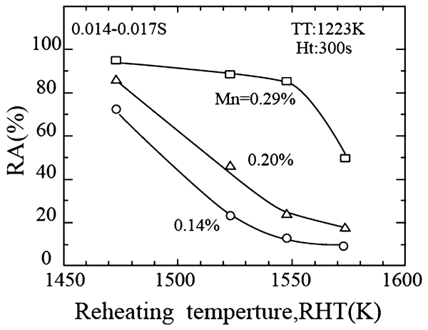
Influence of reheating temperature on RA at the tensile temperature of 1223 K for hold time of 300 s in 0·014–0·017 wt-% sulphur steels138
The improvement of hot ductility at lower reheating temperatures in Fig. 26 cannot be explained as a result of a decrease in dissolved S during the reheating process.138 Such a dramatic increase in RA from 50% to 85% due to decreasing RHT only from 1573 to 1548 K for a short holding time of 600 s at these temperatures cannot be induced by the thermal equilibrium precipitation that decreases dissolved S. Such a dramatic increase in RA can only be induced by the grain boundary effect of TNGS. Westbrook and Floreen141 studied the kinetics of grain boundary S segregation and the mechanical properties of nickel. They concluded that segregation of a solute impurity even at concentrations less than 1 ppm can affect both bulk and microstructural properties of an otherwise ductile material.
Calvo et al. 142 analysed the hot ductility of C–Mn steel containing a residual presence of Cu and Sn. The samples were subjected to different reheating (solution treatment) temperature before the tensile tests. Tensile test temperatures were in the range of 650–1100°C and strain rate was 5×10⁻³ s−1. Results indicated that the width and depth of ductility trough were dependent on the reheating cycle. When samples were reheated at 1100°C, the fracture was a combination of both intergranular and interdendritic modes. Higher reheating temperatures, i.e. 1330°C, induced a predominantly intergranular fracture. It was thought that grain boundary segregation was the key factor for the observed behaviour and the effect of TNGS temperature difference was used to explain the behaviour. They considered that TNGS occurs during cooling from a high solution treatment. Since the vacancy concentration increases with temperature, stronger segregation is expected higher reheating temperatures because of the higher temperature gradient between the reheating and the test temperatures.142
In summary, the results presented here demonstrate a behaviour that is consistent with the effect of TNGS temperature difference instead of an explanation those based on precipitation, phase equilibrium, or equilibrium segregation.
Ductility trough induced by stress induced segregation
The temperature difference between the solution temperature and the tensile test temperature is the precondition for the occurrence of TNGS peak temperature and ITE. Inconel 718 alloy and derivatives were solution treated from 954 to 982°C for 1 h, then rapid cooled to 788°C, held for 2–8 h, furnace cooled at 56°C min−1 to 649 or 704°C held for 8 h, air cooled to room temperature.143 This alloys exhibited a ductility trough between 750 and 850°C during elevated temperature tensile test, as shown in Fig. 27.144 It is obvious that the ITE for Inconel 718 and its derivatives occur in the absence of temperature difference between the solution temperature and the tensile test temperature. In this case, the ITE is not induced by TNGS peak temperature. According to the theory of SNGS peak temperature, as shown in Fig. 10, for the elevated temperature tensile tests, a tensile test temperature must exist, at which the critical time of impurity SNGS is close to the ESAT of the tensile test, and a maximum of SNGS occurs. When the test temperature increases or decreases, the critical time of SNGS is shorter or longer than the ESAT of tensile test and SNGS concentration is lower. This induces ITE. Thus, the ITE in Ni–Cr–Fe(Nb) superalloy in Fig. 27 is induced by the SNGS peak temperature rather than TNGS peak temperature. Such an effect of SNGS peak temperature on ITE is confirmed in the forthcoming section.
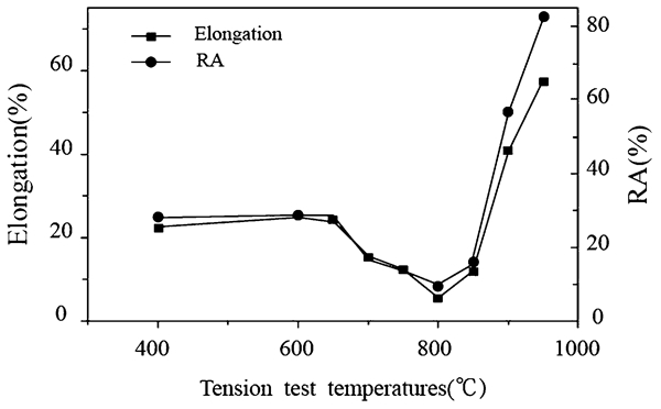
Variations of elongation and RA in Ni–Cr–Fe(Nb) superalloy with the tensile test temperature144
Movement of ductility trough
It is obvious that decreasing strain rate prolongs the ESAT during the tensile test. Prolonging the ESAT moves the SNGS peak temperature to a lower temperature, as shown in Fig. 10. This means that the temperature corresponding to the ductility trough shifts to lower temperatures with decreasing strain rate and to higher temperatures with increasing strain rate. This anticipated behaviour has been experimentally validated a number of times in different alloys.
In Otsuka’s experiments with Al–5·2Mg alloy,145 the temperature of the ductility trough T min was decreased from about 380°C (653 K)at the highest strain rate of 10−1 s−1 to about 230°C (503 K) at the slowest strain rate of 10−5 s−1 as shown in Fig. 28.
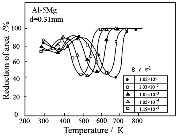
Reduction in area as a function test temperature for Al–5Mg alloy, after deformation at different strain rates from 1·02×10−1 to 1·19×10−5 s−1 145
The study by Horikawa et al. 146 has shown that coarse grained Al–5Mg alloys experienced to intergranular fracture and there is a corresponding decrease in ductility at temperatures between 150 and 400°C during tensile tests at a slow strain rate (8·3×10−4 s−1) in an inert environment. The ductility values of the specimens containing two different Na levels (0·01 and 1·8 wt-ppm), tested at a strain rate of 8·3×10−4 s−1 are presented in Fig. 29a as a function of test temperature. There is a deep ductility trough at a temperature of ∼300°C for the 1·8 wt-ppm Na doped specimen, while there is none for the 0·01 wt-ppm Na doped one. Thus, sodium had a significant effect on the hot ductility of the alloy leading to serious deterioration in hot ductility in the range of 150–400°C. As shown in Fig. 29b , the temperature corresponding to the ductility trough shifts to lower temperatures with decreasing strain rate from 300°C at 8·3×10−4 s−1 to 250°C at 8·3×10−5 s−1 at the same bulk level of Na (1·8 wt-ppm).
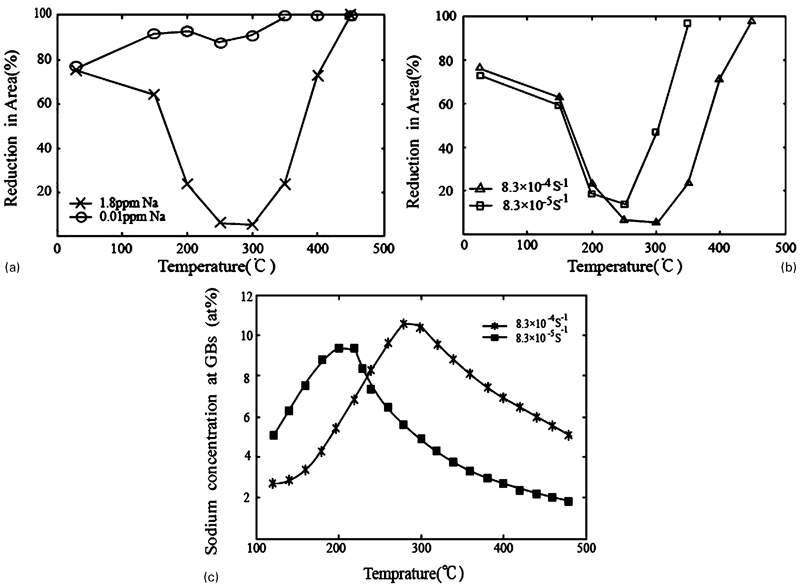
a Hot ductility % RA as a function of temperature for specimens doped with 1·8 and 0·01 wt-ppm Na and tested at a strain rate of 8·3×10−4 s−1, and b data for specimens doped with 1·8 wt-ppm Na, and tested at two different strain rates.146 c Predicted sodium grain boundary concentration as a function of temperature during tensile test at two different strain rates for the specimens doped with 1·8 wt-ppm Na (% strain = 7·5)147
Chen et al. 147 analysed Horikawa et al.’s results with SNGS and suggested that the non-equilibrium segregation of Na should play an important role in reducing hot ductility of this alloy. As shown in Fig. 29c , based on NGS theory, they predicted grain boundary Na concentration as a function of temperature for tensile test at two different strain rates for the alloy doped with 1·8 wt-ppm Na. The temperature corresponding to the grain boundary Na concentration peak shifted to lower temperatures with decreasing strain rate for the bulk level of Na of 1·8 wt-ppm from 300°C at 8·3×10−4 s−1 to 250°C at 8·3×10−5 s−1.147 Comparing the results in Fig. 29, it is suggested that SNGS peak temperature movement of Na induces the movement of ductility trough.
Ductility trough movement was also found in a CuNi25 alloy by Nowosielski et al. 148 It was proved that the increase in strain rate led to the displacement of ductility minimum temperature to a higher one, as illustrated in Fig. 30. The plots show that ductility minimum temperature for CuNi25 alloy deformed at the strain rate of 2·7×10−3 s−1 is obtained at 475°C with elongation of 15% and at 500°C with RA of 13%. Ductility minimum temperature at strain rate of 2·7×10−1 s−1 occurs at 525°C with elongation of 13% and between 525 and 550°C with RA of 13%.148
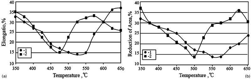
a Elongation as a function of test temperature for CuNi25 alloy tensile deformed at with strain rates: (1) 2·7×10−1 s−1 and (2) 2·7×10−3 s−1. b Reduction in area as a function of test temperature for CuNi25 alloy tensile deformed at strain rates of (1) 2·7×10−1 s−1 and (2) 2·7×10−3 s−1 148
The movement of ductility trough was also found in a Fe–17Cr stainless steel by Sun et al. 149, 150 The tensile specimens were heated at 1573 K for 1 h for homogenisation and quenched in water, then heated to the tensile test temperature for 0·5 h. Tensile tests were subsequently performed at constant strain rates. ITE was observed in the temperature range of 750–1050 K and shifts to a higher temperature at a higher strain rate.149, 150 The minimum RA appeared at 960 K for strain rate of 1·43×10−1 s−1, at 930 K for 1·43×10−2 s−1, at 900 K for 1·43×10−3 s−1, at 870 K for 1·43×10−4 s−1 and at 820 K for 1·43×10−5 s−1, as shown in Fig. 31. Therefore, the temperature corresponding to minimum RA shifts to a lower temperature, when the strain rate decreases. Sun et al. 149, 150 concluded that it is the impurity segregation of P and S to grain boundaries that enhances the ITE. Such a movement of ductility trough induced by variation in strain rate in Fe–Cr17 steel cannot be explained by the dynamic recrystallisation. Qualitative amounts of sputtered phosphorus and sulphur ions on the fracture surface were measured by an ion mass analyser for the Fe–17Cr alloy in Ref.150. It is indicated that the phosphorus and sulphur contents from intergranular fractured surfaces of all specimens fractured at embrittlement temperatures are very high and they segregate on fracture surfaces to enhance the embrittlement. But the phosphorus and sulphur content from all the fractured surfaces of specimens at non-embrittlement temperatures are very low and they did not segregate on the fracture surface.150
Changes in reduction in area of Fe–17Cr alloy after heat treatment (•:
The movement of ductility trough occurs in different alloy systems, such as copper alloys, Al–Mg alloys, Fe based alloys and so on. It is unlikely for the trough movement to be induced by precipitation in a number of alloy systems. The present ductility trough movement due to the shift of strain rate is consistent with the SNGS model. The hot ductility trough can be induced both by TNGS and SNGS. Only when the ductility trough is induced mainly by SNGS, the trough can move to higher temperature with the increase in strain rate in the tensile test.
Void formation at grain boundaries
Sun et al. 149 reported voids at grain boundaries in ferritic 17Cr stainless steel specimens fractured at intermediate temperatures (Fig. 32). They thought that the void formation at or near grain boundaries during tensile deformation may be responsible for the ITE of this steel.149 Liu et al. 16 reported that the specimens of ITE failed in an intergranular mode and were characterised by nucleation, growth, and coalescence of voids in high purity Fe–S alloys. Voids can nucleate at S segregated grain boundaries in the absence of second phase particles.16 In another instance, Tacikowski et al. 151 reported that in ultrahigh purity Fe–S alloys, S decreases hot ductility by decreasing grain boundary cohesive strength (or energy) as a result of grain boundary segregation. Independent of the mode of fracture (dimple ductile or intergranular), the mechanism always seems to be the nucleation of voids at grain boundaries containing S.151 Similarly, Tacikowski and Kobylanski152 also reported voids nucleated at aluminium nitrides in the presence of segregated S. Kizu and Urabe138 also reported that microvoids nucleate at precipitates of (Fe,Mn)S present at the grain boundaries in sulphur containing low manganese mild steels. They considered that when stress increases, the microvoids are formed. When the voids coalesce, intergranular non-ductile rupture occurred.138 But in Kizu and Urabe’s tests,138 the specimens were deformed at a strain rate of 22 s−1 until final fracture occurred. In such a fast strain rate, the duration of stress is small to produce microvoids. Thus, the microvoids most likely occur during the holding time of 300 s at each tensile temperature prior to the start of tensile test.

Optical microstructure of specimen fractured at 820 K at strain rate of
Why does the intergranular segregation of S nucleate cavities during tensile tests? As mentioned in the section on ‘Theoretical frame of non-equilibrium grain boundary segregation’, the vacancies combine with impurity atoms, such as S and P, to form complexes, which diffuse to the grain boundaries to induce SNGS and TNGS. Xu24, 25 formulated the vacancy concentration in the grain boundary region induced by the elastic tensile stress under anelastic relaxation equilibrium, given by equation (8). The following assumptions were made: (1) one complex contains statistically one vacancy and one solute atom; (2) almost all the increase in solute and vacancy in the grain boundary region are produced by the diffusion of complexes to grain boundaries.24 Thus, the increase in the concentration of vacancies induced by the elastic tensile stress as shown in equation (8) is equal to the increase of solute atom as shown in equation (9) in the grain boundary region for the SNGS. The increase in vacancy induced by thermal cycle for the TNGS is equal to that of solute atom in equation (3).21, 22 As a result, such an increase in vacancy concentration for TNGS and SNGS, above the equilibrium concentration, concentrates at grain boundaries to form voids. Thus, the fact that the intergranular segregation of S nucleates cavities during elevated temperature tensile tests can be viewed both from the viewpoint of mechanism of vacancy–solute atom complex of SNGS and TNGS and the ITE mechanism of SNGS and TNGS. The observed void phenomena accompanying ITE is consistent with the model of NGS rather than with precipitation or EGS.
The ITE is complicated phenomenon in metals and alloys. To date, several interpretations of ITE have been proposed, namely, intergranular phase transformation,130, 131 grain boundary shearing or sliding,132, 133 gas phase embrittlement,134 decohesion of glide plane,19 dynamic strain aging (dynamic recrystallisation)118, 135 and grain boundary segregation.136 Some of them accompany phenomenon of ITE process, such as grain boundary shearing or sliding and decohesion of the glide plane; some of them enhance the ITE in a particular material and for a particular process, such as intergranular phase transformation, gas phase embrittlement and dynamic strain aging. The intergranular phase transformation and dynamic strain aging, such as the transformation from austenite to ferrite and dynamic recrystallisation may have been an important influence on ITE only for the steels that can form ferrite or precipitates and the strain rate is low to produce dynamic recrystallisation.117, 118, 137 The mechanism of impurity NGS appears to be applicable at least for examples in polycrystalline metallic materials discussed here in the paper that have trace impurities. However, we cannot ignore possibilities of ITE trough during continuous casting of HSLA steels which are attributed to ferrite outlining of prior austenite grains, austenite grain size, precipitation in the matrix and at grain boundaries, grain boundary sliding, grain boundary migration and dynamic recrystallisation when strained at low strain rates (10−3 s−1) within the creep range.117, 118, 137
Implications and applications to other ferrous and non-ferrous alloy systems
Stress-induced segregation and intergranular decohesion
In the section on ‘Stress-induced non equilibrium grain boundary segregation’, we discussed the characteristics of stress induced grain boundary segregation. It is important to elucidate the phenomena from the viewpoint of its impact on fracture behaviour in systems other than steels and nickel base alloys. In this section and next section, we extend the discussion of grain boundary segregation to stress relief cracking and creep, to list a few. Furthermore, we relate the behaviour to thermodynamics of segregation. Fracture occurring via quasistatic intergranular decohesion, generally along the grain boundaries, caused by the stress driven diffusion of a surface adsorbed embrittling element (i.e. one with a high mobility and low binding energy), is referred as ‘dynamic embrittlement’.153 – 161 Intergranular fracture occurs when adequately high stress is applied to a material in the presence of a surface active low melting-point element. Striking examples of its occurrence in metallic alloy systems are: (1) S in high strength structural steels,158, 164 (2) O in Cu–Be alloys,158 (3) Sn in bronze,153, 157 (4) S in Cu–Cr alloys159, 160 and (5) O in nickel base alloys and intermetallics.154, 162, 163 Intergranular decohesion occurs at the rate of 10−5–10−3 cm/s that are ∼8–10 orders of magnitude slower than the conventional brittle facture.162, 163
The unified key elements as identified from the above listed examples of dynamic embrittlement are:153 – 163
first, the separation occurs from decohesion, almost always along the interfaces, caused by the ingress of a surface active element from a free surface under the influence of stress (residual or applied)
second, the crack growth process is of quasistatic nature in polycrystalline alloys
lastly, the decohesion process is accompanied by plasticity.
It was underscored that the interfacial weakening and consequent brittle cracking occur as a result of the application of stress across the interface (in the present case, grain boundary).153 – 164 That is, the foreign element enters the interface from the free surface in response to the application of stress. Thus, the free surface might have a high concentration of the embrittling element, and the interface initially does not contain the required concentration of the embrittling elements to produce interface decohesion upon application of stress. This characteristic differentiates the phenomenon from the well known impurity induced temper embrittlement of steels and intergranular embrittlement of alloys, in which the impurity segregation has occurred before the application of stress, and intergranular cracking occurs at high stress and at low temperatures, where diffusion is not an aspect of concern.153 – 157
There is presently a renewed interest concerning the role of stress on intergranular segregation in steels, aluminium and copper alloys since the spectre of impurity contents looms large in the context of increased recycling of materials as well as in the design of complex alloy chemistries to meet enhanced demands on mechanical properties. The research in this subject area was first motivated by a study of brittle mode of stress relief cracking of low alloy steels.164, 165 This was observed in the heat affected zones of welds, where the steel was heated to high temperatures above about 1200°C and cooled rapidly (e.g. by heat loss to the surrounding colder metal). The cracking occurred when the weldments were subsequently given a stress relief treatment in the temperature range of 500–600°C to allow residual thermal stresses to be relaxed by creep. It was first thought that the phenomenon of stress relief cracking was caused by the same impurities that were responsible for temper embrittlement. A significant result was the demonstration that stress relief cracking was, in fact, caused by sulphur rather than by other impurity elements. It was recognised that during the high temperature austenitising treatment, sulphides are dissolved during heating, and this sulphur segregated to prior austenite grain boundaries and reprecipitated during rapid cooling by the surrounding unheated metal. During creep or stress relaxation, internal damage in the form of intergranular cavities occurred, and the surfaces of these cavities were contaminated with highly surface active sulphur. This sulphur was readily available in the prior austenite grain boundaries because of the heat affected zone simulation treatment. In the presence of a tensile stress, either residual or applied, brittle fracture occurred in the sulphur enriched regions. In addition to the potent embrittling nature, the relatively high diffusivity of sulphur in iron led to selective diffusion into the grain boundaries under stress.164, 165
The interest in stress induced brittle cracking was also underscored by the observation of low ductility intergranular fracture of low alloy steels.166 – 174 Two alternate hypotheses173, 175 were proposed and analysed to theoretically describe the brittle mode of intergranular cracking. In one, called the ‘pure drift’ process,173 it was proposed that although the cracking was in fact sulphur induced decohesion, it was caused by the diffusion of sulphur from the bulk to the grain boundaries ahead of the main crack tip. The sulphur was envisioned to be on its way to the free surface, under the influence of the stress field ahead of the crack, and the presence of the stress field made the grain boundaries perfect traps for the diffusion of sulphur. This hypothesis, aside from the absence of theoretical support for the proposed effect of stress on the binding energy of sulphur to the grain boundaries, was inconsistent with the scanning electron microscopy observations.173
Also, the ‘pure drift’ process164 relied on sulphur in substitutional solid solution in the bulk, which meant that a counter flow is required for the case of pure drift of a substitutional solute; the rate of drift is controlled by the bulk diffusion of the slower species, which is iron. This is about 1000 times smaller than that of sulphur at 550°C, and the introduction of this correction would drastically reduce the amount of sulphur build-up at the free surface or grain boundary, and would render it inconsistent with the experimental observations.155 However, the rate of drift may not be necessarily be controlled by bulk diffusion of sulphur, but by wholesale shift of the frame of reference of the lattice, since iron atoms form the bulk lattice. Under these conditions, the ‘counter flow’ is the shift of the lattice such that the rate of the entire process is in reality controlled by the rate of diffusion of sulphur. In the second process,175 it was assumed that the separation of the grains occurs not only by decohesion, but purely as the result of steady state diffusion of atoms. This is a special hypothetical case in which the rate of grain boundary diffusion is considerably faster than the surface diffusion. The main problem with this hypothesis was that there was no reason to suspect that this inversion of normal diffusion behaviour would occur in any metallic system, since it is known that grain boundaries are more rapid diffusion paths than the grains themselves.
Later on, the phenomenon of oxygen induced embrittlement was clearly demonstrated in a study of alloy IN 718 in which the effects of prior static loading in air and in vacuum at 540–650°C on the subsequent low cycle fatigue behaviour were determined.176 Static loading in air produced an oxygen embrittled zone, the length of which increased with stress, temperature and time, and this zone failed by decohesion during the subsequent cyclic loading. This behaviour was labelled ‘stress oxidation cracking’, and indicated that the rate of this cracking had a temperature dependence of ∼60 kcal mol−1.
Boron and hafnium doped Ni3Al alloy tensile tested in air at 600°C also exhibited intergranular brittle fracture.177 Specimens tested in vacuum exhibited transgranular rupture and ∼50% elongation, compared to ∼4% elongation of the air tested specimens. Preoxidation at elevated temperatures without stress did not produce the same intergranular embrittlement; simultaneous exposure to oxygen and a high tensile stress was required to give the embrittlement. This was the hallmark of ‘dynamic embrittlement’, a term that is now used to describe the above behaviour, and involved the combined effects of high crack tip stress, elevated temperature and the adsorption of oxygen at the crack tip. It was suggested that embrittlement was due to a dynamic effect simultaneously involving localised stress concentration, elevated temperature and gaseous oxygen.
Subsequent to the above experiments, the crack growth studies were made in four-point bend specimens in a similar nickel base alloy in the range of 500–760°C, in a constant displacement load relaxation test, using the DC potential drop method.178 Intergranular brittle fracture propagated at rates in the range of 0·1–100 μm s−1, depending on the temperature.
Another way to explain dynamic embrittlement is in terms of pre-existing cracks in the metal effectively closed by the normal compressive stresses on the surface of the sample and so resisting opening during preoxidation at 600°C. The loss of ductility occurred by simultaneous temperature and stress which opened the pre-existing cracks, allowing internal oxidation of the crack surfaces.
In the case of copper base alloys, intergranular embrittlement by oxygen was first noted by Coffin179 in a Cu–Be alloy tested in low cycle fatigue at various partial pressures of oxygen. That was considered to be a rare phenomenon in copper base alloys and emphasised the fact that high stresses, and therefore, high strengths, are required. Subsequently, the dynamic embrittlement phenomenon was recently demonstrated in Cu–Be–Co158 and Cu–Cr alloys by Misra et al. 159, 160
The above observations made in different alloy systems suggested that there are two distinct and different possibilities to visualise the physical effect of stress on grain boundary segregation of elements under conditions of applied stress. First, the applied stress affects the kinetics of grain boundary segregation through its influence on the diffusive rate of solute atoms in the interior of the grains (bulk diffusivity of solute atoms), termed as the ‘kinetic effect’. Second, it also affects the capabilities of grain boundaries to absorb solute atoms. This effect is the ‘thermodynamic effect’, and essentially means that the application of stress results in a free energy change towards a more stable system leading to a change in the equilibrium segregation of solute atoms. Misra and co-workers 67 67,180 adopted the concept of determining grain boundary segregation isotherms181 – 183 to establish a clear distinction between the kinetic and thermodynamic effects of the applied stress.
Grain boundary segregation isotherms were determined through in situ fracture experiments in a scanning Auger microprobe on unstressed low alloy steels isothermally aged for longer periods of time to attain an equilibrium coverage of segregants (Fig. 33)67,
180 and on stress aged specimens with equilibrium coverage in the unstressed condition (Fig. 34).180 An appreciable increase in the grain boundary coverage of sulphur was observed on the application of tensile stress for the first 3 h of stress. However, on stress aging for duration greater than 3 h, the grain boundary coverage of sulphur decreased gradually and finally approached its equilibrium value after about 25 h of stress aging. This approach unambiguously confirmed the effect of applied stress. The change in the grain boundary coverage of sulphur observed on tensile loading in steels with equilibrium grain boundary concentration, implied that the change is the result of the applied tensile stress and is such that the ability of the grain boundaries to absorb sulphur atoms changes on the application of stress. The driving force for the rapid increase in grain boundary concentration of sulphur during the early stages of tensile loading was attributed to the decrease in the chemical potential Δμ of the diffusing atom from one grain boundary site to another (in the case of Fig. 33, from grain boundaries parallel to the applied stress to grain boundaries normal to it) or from a free surface into the interior of a solid. The driving force is given by153
–
155
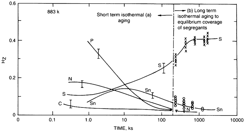
Grain boundary segregation isotherms recorded at 883 K on unstressed low alloy steel. Equilibrium coverage was reached in stage ‘b’ (1). H Z is intergranular Auger peak to peak height of an element normalised with the Auger peak to peak height of Fe
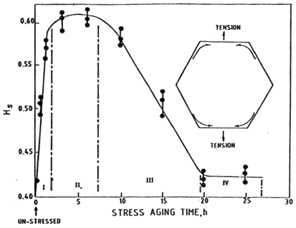
Grain boundary segregation isotherms recorded for sulphur in a low alloy steel in the stress aged condition after prior aging of the specimen in the unstressed condition for ∼ 2160 ks at 883 K. The inset depicts a schematic of the diffusional process involved during the stress aging test. H S is intergranular Auger peak to peak height of sulphur normalised with respect to Fe67, 180
Four stages (I–IV) were delineated in stress aged experiments (Fig. 34) and described as follows. Stage I represented rapid increase in grain boundary sulphur. Stage II was intermediate stage between grain boundary diffusion of sulphur and the commencement of diffusion of host metal atoms. On aging for prolonged durations, the host metal atoms (mostly iron) diffuse and mix with the solute species (stage III), and as a result the sulphur concentration in the grain boundaries returns to its original equilibrium concentration (stage IV). Host metal atoms migrated mainly by grain boundary diffusion, as did the sulphur flux before it, and the return flux of sulphur also proceeded along the grain boundaries, since sulphur atoms going away would be replacing the host metal atoms coming in. The transient behaviour of sulphur was essentially Coble creep induced by the tensile stress.155, 156
From the plots of the type presented in Fig. 33, the rate of intergranular segregation of sulphur (∂H
S/∂t) for stage I was determined for different combinations of stress and temperature, and the activation energy was determined. An increase in the value of ∂H
S/∂t, with increasing applied tensile stress (at constant T) and also with temperature (at constant stress) for the first few hours of tensile aging (stage I: Coble creep regime) followed the relationship: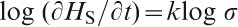
Since the rate of grain boundary segregation of sulphur ∂H
S/∂t was a function of stress, and considering that plating of sulphur atoms in the grain boundaries perpendicular to tensile axis contributed the strain, the Coble creep equation 14184 was applied to the observed behaviour presented in Fig. 33


Thus, the disappearance of the initial increase in the grain boundary coverage of sulphur on stress aging for t>3 h was attributed to the replacement by slow diffusing species that migrate to eliminate the transient sulphur concentration gradient. That is, in thermodynamic terms, the sulphur penetration to grain boundaries under the influence of stress was suggested to be a transient phenomenon, and was a particular manifestation of Herring–Nabarro creep or Coble creep. This kind of phenomenon was experimentally demonstrated in a nickel base alloy,185 and in a magnesium base alloy.186, 187
Bika and McMahon156 envisaged in the situation described above that the transfer of atoms takes place at a comparatively faster rate at grain boundaries, since the lattice diffusion coefficient is smaller than the grain boundary diffusion coefficient. The diffusion process can cause the solid to become longer (and thinner) and thereby allow the tensile stress to do the work. Thus, in the event that internal or external surfaces contain adsorbed elements, such as sulphur, which could lower the cohesive strength of the material, then under these conditions, decohesion is most likely to occur in the diffusion zone leading to brittle cracking. They derived a mathematical equation to calculate the rate of crack advance for the decohesion process. The mathematical equation contained both the usual random mixing term and a term reflecting the work done by the tensile stress when surface atoms diffuse inward and is given by156
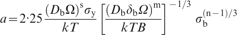
An important aspect of dynamic embrittlement of low alloy steels by sulphur and other non-ferrous alloys is the quasistatic or discontinuous nature of cracking, characterised by intergranular facets containing striations. Illustrations of intergranular facets containing striations in dynamically embrittled Fe–V alloys188 at 550°C are presented in Fig. 35. The striations on the intergranular facets represent crack arrest marks signifying the discontinuous nature of cracking resulting from decohesion on a microscale. The work of Hippsley et al. 173 by acoustic emission technique also indicated that cracking was intermittent. However, such marks were absent in Sn induced dynamic embrittlement of Cu–7·5Sn bicrystals with a Σ5 boundary, and the cracking in the direction of tilt axis appeared continuous.153 This has recently led to the belief that the discontinuous nature of cracking is an artefact of a ‘composite effect’ rather than a fundamental characteristic of the cracking process,153, 154 as briefly outlined below.
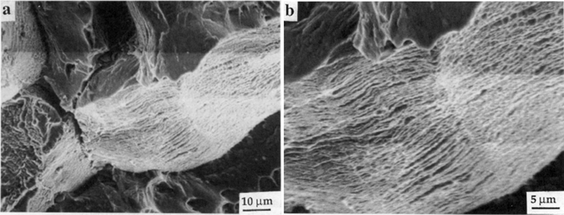
a low and b high magnification scanning electron micrographs of the intergranular facets of dynamically embrittled Fe–V alloy. The periodic striations extend across a few grain faces. Also, seen are ductile regions adjacent to the smooth intergranular facet that provides shielding. The ductile region was a consequence of tearing of regions connecting the intergranular facets188
More recently, Campbell’s group has presented an approach to embrittlement by proposing that grain boundaries are strong and are not expected to decohere.189, 190 An evidence was presented that vacancy clusters do not condense to form voids because the interatomic forces are too great, always collapsing the condensates into dislocation rings or stacking fault tetrahedral. Their hypothesis is that metals unfortunately have nanometre thickness oxide entrained in them from casting process, and the oxides are always in a doubled-over from, constituting an unbonded crack interface in the liquid which is frozen into the solid. Also the same casting processes, particularly vacuum melting and casting furnaces, are particularly bad in introducing such defects into metals, forming easily decohered grain boundaries, favoured substrates for sulphides and other intermetallics.189, 190
Relationship between grain boundary segregation processes and fracture resistance
High strength–high toughness combination and formability continues to be the primary focus of engineering alloys, where the attempt is to either develop newer alloys or maximise the fracture resistance of engineering alloys at specified levels of strength. In this regard, the significant success has been achieved to understand the part played by crystal structure, grain size, grain boundary chemistry, texture and substructural features. In the context of grain boundary segregation and its corresponding relationship to toughness, we describe an important instance of practical significance that has been studied in detail. This section is in sequel to the previous section on ‘Implications and applications to other ferrous and non-ferrous alloy systems’ and merits attention, even though it may not strictly fall under the unified mechanism of intergranular segregation, but is relevant to the subject matter of the review.
In the case of 17Cr–4Ni precipitation hardened stainless steel,193 – 198 the striking variation in impact toughness in the range of 5–120 Nm with bulk % carbon content for identical heat treatment was explained in terms of grain boundary segregation of phosphorus and carbon involving grain boundary interaction processes. Although the tensile properties, yield strength (1075–1115 MPa), and % reduction in area (53–64%) were consistent, for fixed bulk Nb content of 0·28 wt-% (Fig. 36).
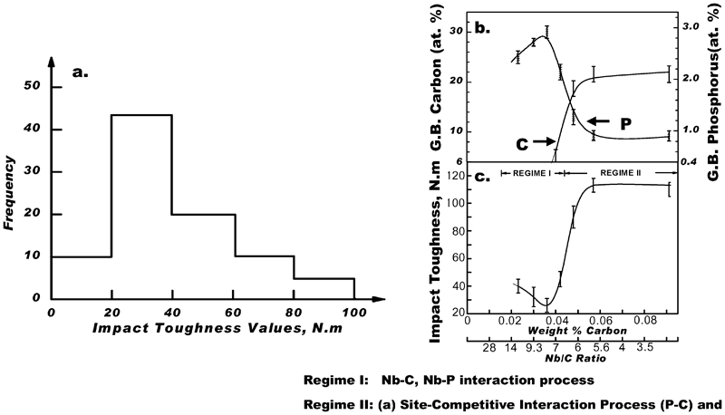
The strong dependence of impact toughness with bulk C content was explained in terms of Nb–C and Nb–P interactions.191 – 196 It was believed that, with increasing bulk C content, the grain boundary concentration of P would increase, because more and more Nb gets tied up with C as NbC, and less is available to interact with P to form NbP. NbP chemical interaction either in the form of clusters or precipitates, and is most likely to occur during aging. This allowed grain boundary segregation of P to increase with bulk C content. Phosphorus segregation was a maximum at a C concentration of ∼0·035%, corresponding approximately to the value necessary to precipitate entire Nb as NbC with no Nb being available for interaction with P. In steel compositions with C contents greater than ∼0·035%, the presence of free or excess C (Fig. 36) effectively displaced P from the grain boundary through P–C, site competitive process, and additionally enhanced grain boundary cohesion. Thus, interactions of the type Nb–P and Nb–C were invoked to explain striking variation in the impact toughness in precipitation hardened stainless steels. The data presented in Fig. 46 into two distinct regimes: (1) a low toughness regime (Nb/C ratio >6 but less than, say, 20) characterised by high grain boundary concentration of phosphorus and NbC formation owing to strong Nb–C interaction; (2) a high toughness regime (Nb/C<6), where grain boundary P is displaced by C through site competition. This segregation of C has two important effects; it alleviates the harmful effect of P and also enhances grain boundary cohesion. Thus, the Nb/C ratio plays an important role in influencing toughness (Fig. 40). It is important to note that even though elements Nb and C in the steel may be within the specified range, it is the ratio that is more important as far as the property requirement is concerned (Fig. 37).
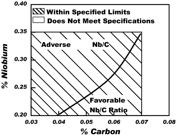
Significance of Nb/C ratio in 17Cr–4Ni precipitation hardened stainless steel to obtain desired toughness
Furthermore, thermodynamic analysis in terms of free energy of segregation for the aforementioned two regimes was attempted196 using Langmuir–Mclean equation186 and Rice and co-workers’ thermodynamic framework.197 The first regime, which was characterised by low impact toughness and grain boundary segregation of P, the grain boundary segregation free energy of phosphorus was obtained from

The values of 
Regime II was characterised by grain boundary displacement of P by carbon (site competition process). Langmuir–Mclean equation was written as


Using Rice and co-workers’ thermodynamic framework198 for treating the embrittlement of interfaces by solute segregation in terms of the ideal work of interfacial separation, 2γ
int, where 2γ
int is conceived to predict the important, if not the exclusive, role in determining the resistance to interfacial embrittlement. Their hypothesis suggests that the control of 2γ
int is the most effective means of enhancing interracial fracture resistance and that the embrittlement (or ductilisation) by impurity solute segregation can be explained in terms of the effect of segregation on 2γ
int, such that198


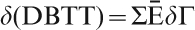


Inverse of the product of impact toughness and atomic % segregant (C or P) as a function of

It was noted from the plot of inverse of the product of impact toughness and atomic % of segregant (Ē versus 


Summary and future outlook
The study of thermally induced and stress induced non-equilibrium grain boundary segregations has established a theoretical system in the last 30 years. The most important application is to successfully elucidate a common mechanism for RTE, ICE in steels and ITE in metals or alloys that has been the subject of materials science and engineering for over 100 years. This is a universal mechanism because it is valid for all polycrystalline metallic materials that have any trace impurity. In the present paper, the experimental evidence for such a mechanism was reviewed and visited from the view point of following six aspects:
First, the critical time of TNGS induces the ductility healing effect in RTE when the tempering time is prolonged, in ICE when sensitising time is extended, and in ITE when the hold time is prolonged before tensile deformation at the tensile temperature of ductility minimum.
Second, the peak temperature of TNGS induces a maximum in intergranular embrittlement for RTE, in embrittlement rate for ICE, and a ductility trough in ITE when samples are isothermally held for an identical time at various test temperatures after quenching from a higher temperature.
Third, increasing the temperature difference of TNGS between solution temperature and the test temperature will increase the degree of embrittlement in RTE, the embrittlement rate in ICE, and depth and width of the ductility trough in ITE.
Fourth, the peak temperature movement of TNGS makes the embrittlement peak shift to a lower (higher) temperature in RTE and in ICE when prolonging (shortening) holding time at various test temperatures after quenching from a higher temperature.
Fifth, the peak temperature of SNGS can also induce a ductility trough in ITE in the absence of quenching before the tensile test. The peak temperature movement of SNGS makes ductility trough shift to a lower (higher) temperature when strain rate decreases (increases).
Sixth, the vacancy–solute complexes in thermally induced and stress induced non-equilibrium grain-boundary segregation diffuse to the grain boundaries and decompose there. Then the solute atoms segregate at grain boundaries to form non-equilibrium grain boundary segregation and vacancies concentrate at grain boundaries to form voids of intermediate temperature embrittlement.
The evidence documented in the literature is consistent with thermally induced and stress induced non-equilibrium grain-boundary segregation models rather than related to precipitation or equilibrium grain boundary segregation. Especially, the three types of intergranular embrittlement, namely, RTE, ICE and ITE, are all relative only to trace impurity. They do not occur in high purity metals or alloys. The states or distributions of these trace impurities and the consequent effects on RTE, ICE and ITE can be controlled by heat treatment. The kinetics of these three intergranular embrittlements is extremely rapid that the heat treatment is effective only at very short time or at lower temperatures. A more detailed interpretation is yet needed.
These three kinds of grain boundary embrittlement are induced by kinetic factors, such as aging time at a particular temperature and cooling rate, and is not an intrinsic property of materials under thermal equilibrium. The ITE in metallic materials is produced because of the performance of present standard of elevated temperature tensile tests. These situations have restricted the service and process of metallic structure materials for over 100 years. A new standard test method must be developed to avoid the ITE for elevated temperature tensile tests of metallic materials. While some of the approaches outlined above may be applicable in the enhancing our current understanding of the subject, it is important to establish test procedure that will provide unprecedented opportunities and a promising platform to evaluate structural metallic materials. To this end, a great deal of experimental work is required to produce database.
Footnotes
Acknowledgements
The authors (XT, ZL and WK) acknowledge support of the National Nature Science Foundation of China (grant nos. 51171050, 51001030 and 51001011) and acknowledge the considerable comments of referees due to the significant revisions to this paper according to their suggestions. R. D. K. Misra acknowledges support from Center for Structural and Functional Materials, University of Louisiana at Lafayette, USA. One of the authors (RDKM) also acknowledges discussion with Professor Charles McMahon, Jr that took place several years ago.