
Abstract
High volume application of lightweight materials is the key to improving fuel efficiency and vehicle performance, and decreasing exhaust emissions to address environmental concerns. Currently, magnesium alloys, which are the lightest structural materials, represent only ∼0·3% of an automobile weight. One of the most important parameters in controlling the properties of magnesium and its alloys is melt cleanliness, manifested mainly in inclusions. The presence of such inclusions will strongly influence the mechanical properties and corrosion resistance of structural components. This paper gives an overview of the current state of knowledge pertaining to magnesium melt cleanliness. It describes the nature and origin of the inclusions, the methods for assessing the cleanliness of magnesium, the methods used to control inclusions in the melt and the relationship between melt cleanliness and the properties of magnesium castings.
Introduction
Fuel consumption reduction (and the consequent reduction in harmful exhaust emissions) is a main concern of the automobile industry today. Automobile weight reduction is one of the primary means to achieve this goal. The observed increase in the use of aluminium (Al) and its alloys in automobiles is a direct consequence of the pursuit for weight reduction in the past decades.
Recently, magnesium (Mg) alloys have been considered as candidate materials to replace Al alloys and further reduce the vehicle weight, since Mg alloys are 35% lighter than Al (1·74 g cm−3 for Mg 1 as compared to 2·74 g cm−3 for Al 2 ). Further, Mg alloys exhibit good damping capacity, high impact resistance and a high strength to weight ratio. In addition, Mg alloys are recyclable, thus lessening their impact on the environment. Magnesium alloys have been implemented in various applications, specifically in the automotive industry as shown in Table 1.
Despite these advantages, the average use of Mg in North American automotive vehicles represents only 0·3% of the total vehicle weight, as shown in Fig. 1.
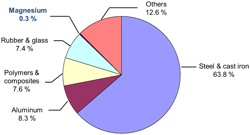
Vehicle materials distribution for a 1500 kg (average) North American vehicle 5
Comparison of Mg and Al mechanical properties (Table 2) shows that Mg alloys are at a disadvantage against Al alloys, as they exhibit lower ultimate tensile strength (UTS) and yield strength (YS), as well as lower elastic modulus than Al alloys. The ‘gap’ between Al and Mg alloys can even be exacerbated if the melt processing is poor. In particular, the ductility of Mg alloys can exceed that of Al, and that may be advantageous in some applications, unless melt processing negates this benefit. The strength and ductility of Mg alloys need to be improved, thus rendering them as viable alternatives to aluminium alloys. Improving the melt quality or melt cleanliness is key to achieving these goals.
*All die cast, except 319·0-T6, 332·0-T5, 356·0-T6 and A356·0-T61 (permanent mould).
N/A: none available.
Ensuring good melt quality involves:
the control of trace elements
the reduction of dissolved gases in the metal
the removal of inclusions from the melt.
Variations in the chemical composition of the alloys and/or in the defect parameters (type, morphology, etc.) will affect the homogeneity and quality of the final product in terms of mechanical properties or surface appearance. 10,11
Chemical composition
Since 1922, the melting and the purifying of Mg and its alloy have had a long development. 12,13 It has been known for years that even trace amounts of iron (Fe), nickel (Ni), copper (Cu) or cobalt (Co) have deleterious effects on the corrosion resistance of Mg alloys. 14,15 Iron is the most common impurity which originates from the steel melting crucibles. Nickel contamination occurs when high Ni stainless steels are immersed in the Mg melt (e.g. handling tools or thermocouples). Copper contamination can arise from Cu bushings in recycled parts. 1 Cobalt may originate from Co based paints, 14 but is not a common impurity in Mg alloys and no tolerance limit has been specified for Co.
These elements have to be removed to ensure consistent quality of the final product. Minimisation of these heavy metals in Mg melts can be realised by proper selection and control of raw materials, alloying additions procedure, handling/melting tools and equipment (e.g. use of nickel free low alloy steel crucibles 1 ) and allowing the impurities to settle to the bottom of the crucible. 16 Iron can be removed through the addition of manganese to molten Mg. The melt is then cooled, resulting in the precipitation of Fe–Mn–Al intermetallic. Control of melt temperature is thus crucial.
Hydrogen
Hydrogen solubility is greater in the liquid than in the solid state for Al and Mg alloys. For Al, the maximum solubility of hydrogen in the liquid and the solid near the melting point are 0·65 cm3/100 g and 0·034 cm3/100 g respectively. For Mg, they are 27 cm3/100 g and 19 cm3/100 g respectively. 17 The solubility of hydrogen in molten Mg is significantly higher than in Al. However, molten Mg saturated with hydrogen rejects only 32% of hydrogen during solidification as compared to aluminium that rejects 95%. 14 If the concentration of hydrogen is above the maximum solid solubility, formation of pores can occur upon solidification. 2 This represents a serious problem as porosity affects the mechanical properties and the surface quality of castings. The acceptable hydrogen levels for Al and Mg alloys are 0·1 cm3/100 g or lower 18 and 15–20 cm3/100 g, 4,19 respectively. The level of hydrogen can be reduced by bubbling chlorine or an inert gas through the melt. 12,20
There is no commercial instrument available to measure hydrogen content in Mg melts. Researchers have utilised different techniques (e.g. helium bubbling, vacuum extraction, complete combustion of a Mg sample) 21 to measure hydrogen concentrations, sometimes making the results difficult to compare and unreliable. 22
Inclusions
Unlike Al alloys, Mg alloys form a loose, permeable film which does not protect the molten metal from further oxidation. Consequently, molten magnesium will oxidise and burn rapidly in contact with air if special precautions are not taken (e.g. use of flux, cover gas or alloying additions such as beryllium). 1 The high oxidation potential of Mg usually results in inclusion contents 10–20 times higher than that of Al (0·1–10 ppm for pure Al, 10–200 ppm for pure Mg). 23 Inclusions in Mg alloys reduce mechanical properties, are detrimental to surface finish, increase porosity and exhibit a tendency to increase corrosion. 24,25
The maximum allowable concentrations of the major impurities in Mg alloys and the methods to remove them are summarised in Table 3.
Impurity levels in Mg alloys
There is a need to understand and control all aspects of metal handling and processing to improve the consistency of quality and properties of the cast product. This also applies to Mg recycling, for which the large amount of scrap runners, overflows, flash and rejected castings from Mg die casting processes requires careful control of melt practices to ensure metal quality. 29,30 Many efforts have been devoted to improve and assess the melt cleanliness of Al alloys. In comparison, limited information is available for Mg alloys. The techniques used for Al were generally applied to Mg. However, due to the reactive nature of Mg, the adaptability and applicability of these techniques to Mg melts can be challenging. This review paper is written with a focus on the characterisation and formation of inclusions within Mg melts and covers their assessment, control and effects on properties of the alloys.
Inclusions in magnesium alloys
Characterisation of inclusions in magnesium alloys
Inclusions present in molten Mg can be categorised into two major groups: 31
non-metallic inclusions: these include oxides and nitrides; sodium, magnesium and potassium based chlorides; aluminium and calcium based carbides, magnesium based sulphides (MgS), fluorides (MgF2) and sulphates (MgSO4). Oxides are the most predominant non-metallic inclusions, followed by nitrides
intermetallic inclusions: these include iron rich intermetallic phases, which precipitate during iron removal. Almost all intermetallic inclusions contain iron.
Both inclusion types are potentially harmful to the properties of Mg alloys, in particular tensile strength, elongation and corrosion resistance. Further, description of the influence of inclusions on the properties of Mg alloys is discussed in the section on ‘Effect of inclusions on properties of magnesium alloys’. The characteristics of the various inclusions found in Mg alloys are summarised in Table 4, and the typical inclusions are shown in Fig. 2.
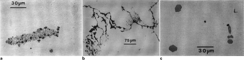
Optical micrographs of a an oxide cluster in AZ91 alloy, b a ‘snaky’ oxide in AM50 alloy and c Mn–Al particles in AM60 alloy 34
Origin of inclusions in magnesium alloys
Reaction with air
During the melting process, molten Mg reacts with oxygen to form magnesium oxide (MgO) when the melt is exposed to the atmosphere. 31,35 Molten Mg can also react with the moisture in air to form MgO and hydrogen, which can result in a fire or explosion. Therefore, all tools to be used must be dry/preheated before immersion in the melt. Water should not be used to fight magnesium fires. 1 The casting process, depending on the pouring technique and gating design, almost always leads to some melt turbulence, which entraps inclusions and exposes a fresh melt surface to the atmosphere, further increasing the number of inclusions in the melt. Stirring, charging, ladling, poor venting, removal of dross and sludge and excessive movement of the mould before solidification is complete 12 also promote the entrapment of oxides. Oxide defects exhibit various morphologies, from particles to films. The oxide films can measure up to 50 μm in length with a thickness of 0·5 μm. The oxide particles are commonly seen as clusters less than 50 μm in diameter. Both oxide films and clusters have high surface to volume ratios and cannot be removed by melt settling. 35
Magnesium nitrides (Mg3N2), which form as a result of the reaction of Mg with nitrogen, may appear together with oxide clusters. As can be seen in Table 5, the Gibbs free energy associated with the oxidation of magnesium is more negative than the Gibbs free energy associated with the formation of magnesium nitride, meaning that Mg preferentially reacts with oxygen over nitrogen. Magnesium nitride will not form unless the partial pressure of oxygen becomes extremely low. 35 There is no indication that nitride inclusions appear independently of oxide inclusions.
Reactions with fluxes
Fluxes are used to protect magnesium melts from oxidation and for refining (removal of inclusions). Flux inclusions (e.g. MgCl2, CaCl2) occur if unabsorbed protective flux remains on the metal surface, the flux is not viscous enough, there is brittle or powdery flux due to long handling, pouring is too fast or if there is incomplete removal of the flux adhering to the lip of the pot before pouring. 38 Magnesium chloride in the flux can react with oxygen and water in the air to form MgO, which can become entrapped in the casting. 39 Similarly, the use of boride containing fluxes could lead to the formation of FeB inclusions. 40 Considerations related to flux entrapment and melt loss 41 led to a shift to the use of protective atmospheres. 42
Reactions with protective gases
Protective atmospheres 43–52 are used to prevent oxidation or burning of molten Mg and consequently to reduce the formation of inclusions in the melt. Some cover gases, including sulphur dioxide (SO2), sulphur hexafluoride (SF6), hydrofluorocarbons (HFC) and fluorinated ketones (FK), modify the natural oxide film such that Mg vaporisation is suppressed and reactive gases are excluded. For example, sulphur dioxide reacts with Mg to form MgSO4, MgO or MgS. 46 With SF6, HFC and FK, the reaction products are MgO and MgF2. 43–45,47–52 All these compounds can enter the melt and lead to the formation of inclusions. Although protective gases may lead to the formation of inclusions, their absence would be more detrimental to the properties of Mg alloys. Proper melting, handling and pouring procedures should minimise their formation.
Reactions during melt treatment and alloying
Inclusions can be introduced during the process of iron removal using manganese. With the addition of manganese, intermetallic particles containing iron, manganese and aluminium form. 31 Inclusions can also result from degassing and grain refinement by the addition of hexachloroethane (C2Cl6), calcium cyanamide (CaNCN) or by the addition of alloying elements (e.g. Al4C3 in Mg alloyed with Al). 31
Reactions during casting
During casting, poor running system design is generally associated with high surface turbulence and greater entrainment of oxide films. The entrained oxides are typically double oxide film defects (bifilms) comprised of folded MgO films. 53,54 The high reactivity of Mg results in rapid formation of MgO films during pouring that quickly thickens to produce a tube of oxide that surrounds the falling metal stream. This tube of oxide is not in danger of becoming entrapped within the liquid metal if the oxide film is unbroken. A similar phenomenon occurs in Al alloys and is due to the same mechanism of rapid thickening of oxide films. 18 The oxide film forming at the surface of the Al melt is relatively thin and elastic as compared to the thick and cracked oxide film forming at the surface of the Mg melt. As a result, Mg alloys may be more prone to bifilm formation than Al alloys.
Inclusions can also be generated during die casting from oxidation in the shot sleeve, entrapment of air during casting and absorption of lubricants spread on the die surface. 1,11,14,31 In sand casting, turbulent flow may cause sand grains to detach from the mould wall and be entrained within the Mg melt, with which they react. The inclusions formed are called ‘reacted sand inclusions’. 14,31,55
Assessment of cleanliness of magnesium melts
A summary of the methods used or considered to assess the metal cleanliness in the Mg industry is shown in Table 6, but none of these methods is considered as a standard for determining Mg melt cleanliness.
Methods for metal cleanliness assessment used or considered for use in magnesium industry*
*OM: optical microscopy; SEM: scanning electron microscopy; EDS: energy dispersive X-ray spectroscopy; IAS: image analysis systems; GD: glow discharge; MS: mass spectroscopy; AES: atomic emission spectroscopy; FNAA: fast neutron activation analysis; ASES: arc spark emission spectroscopy; LIBS: laser induced breakdown spectroscopy; LiMCA: liquid metal cleanliness analyser; NSD: number size distributions; PoDFA: porous disc filtration analysis.
Metallographic techniques
Classic metallographic techniques
Classic metallographic techniques involve the examination of ingot slices to determine the presence of inclusions. It allows the determination of inclusion amount, size, shape and distribution. Metallographic analysis can be combined with image analysis to determine the particle size, number of particles, percentage of oxide in the sample, or with scanning electron microscopy (SEM) and energy dispersive X-ray spectroscopy (EDS) to determine the nature of the inclusions and the possible source of melt contamination. 56 However, optical metallography requires multiple steps: sectioning, grinding, polishing and examination. The technique is therefore time consuming and expensive. Also, the sample size is relatively small, possibly leading to results which are non-representative of the sample.
Humidity test
The humidity test is used in the industry to detect and identify flux inclusions in Mg alloys. The surface to be examined is carefully ground and polished. The prepared specimens are then placed in a chamber where humidity conditions are controlled (e.g. 95% relative humidity at 38°C 1 ). Corrosion occurs at the site of certain inclusions, others being relatively unaffected. The corrosion products are then examined by microchemical techniques to identify the inclusions. 22 However, the results are available only after sufficient corrosion on the sample has occurred which can typically take 24–48 h. Fracture ingot surfaces are sometimes exposed to high humidity in a humidity chamber. Salt inclusions pick up moisture and bloom, indicating the presence of fluorides and chlorides. 75
Techniques based on filtration of liquid metal
Hydro magnesium inclusion assessment method (HMIAM)
In the hydro magnesium inclusion assessment method (HMIAM) or vacuum filtration technique, a known volume of melt is drawn through a stainless steel filter by vacuum. The inclusions are retained on top or within the filter (Fig. 3). Upon solidification and cooling, the filter and its contents are sectioned parallel to the flow direction and examined using an optical microscope. The amount of inclusions is determined in terms of volume of particles per unit weight of metal drawn through the filter. The major advantage of HMIAM is that sampling is performed directly in the melt. 31,35 However, this method can be considered too time consuming. 57 The quantity and morphology of oxides in ingots or die cast components may also be different from those observed on the filter due to different solidification conditions (e.g. melt temperature). 58
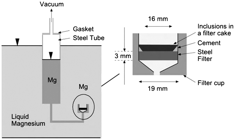
Schematic of the hydro magnesium inclusion assessment method 3
Pressure filtration technique: PoDFA and Prefil
Both PoDFA (porous disc filtration analysis) and Prefil techniques involve forcing a known amount of molten metal under pressure through a filter. In the PoDFA method (Fig. 4), the inclusions concentrated inside or on top of the filter are examined metallographically in terms of size, colour and morphology. 31,35 In the Prefil test, the flow rate of molten metal through the filter is measured and used as an indication of the melt quality: clean metals will flow quickly, whereas inclusions in molten melts build up on the filter surface and reduce the flowrate. These two methods have been applied to measure the melt quality of Al melts, but it was only recently that they were adapted to Mg melts. 59
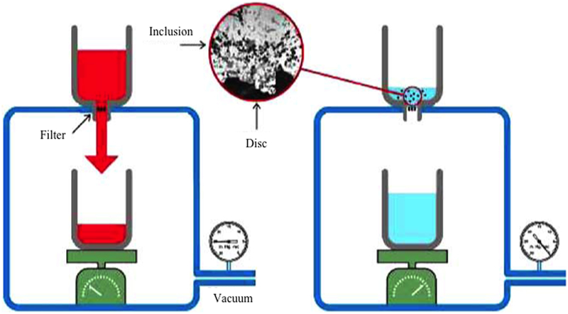
Schematic of the pressure filtration technique 76
Self-gravitation filtering technique
In the self-gravitation filtering technique, specifically designed for Mg alloys, a filter tube containing two sintered metal fibre filter discs is immersed in the melt, allowed to be preheated for 3–4 min and then lifted up out of the melt at a constant speed. As the tube rises, the metal flows through the filters by self-gravitation. The filter cake thickness is correlated to the inclusion content, thereby obtaining an estimation of the melt cleanliness. The inclusions collected on the filter discs can be subsequently analysed by optical microscopy. 60 The technique is still under development to enable the monitoring of the filtration rate.
Techniques based on melt centrifugation and sedimentation
This technique is based on the separation of phases with different densities. The samples are heated to 720–800°C, held isothermally for 5 min and then centrifuged at high speed (200–2500 rev min−1) until the melt solidifies. The temperature is measured continuously with a thermocouple located below the crucible. 61 During this period, inclusions are sedimented at the bottom of the crucible. The inclusions are subsequently analysed using optical microscopy. Experimental results showed that (Fe,Mn)3Si particles present in Mg melt could be analysed by this technique. However, the method can only be used for particles larger than 2–4 μm in diameter. Further, this technique is time consuming and oxides and nitrides in Mg alloys are difficult to analyse.
Fracture surface examination
Generally, there are more inclusions visible on a fractured surface, as fracture often propagates along inclusions. Fractography is thus a quick and simple method used to assess melt cleanliness. Specific methods based on fracture surface examination have been developed and presented in the following sections.
K-mould method
In the K-mould method, a flat plate casting with four cast-in knife edge notches is produced. The notches serve as fracture points (Fig. 5). 31,35 The design of the knife edges in the mould enhances the efficiency of capturing the inclusions on the fracture faces. Multiple samples of the plates are cast and fractured immediately after solidification. The fracture surfaces are examined visually for inclusions. The inclusion level is expressed as the number of defects seen per number of fracture surfaces examined.
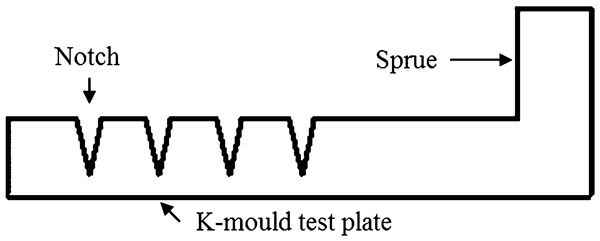
K-mould method 31
The K-mould is a simple shop floor test for detecting inclusions. The main advantages of this technique include quick results, minimal cost, low required level of operator skill, sampling flexibility and sample retention. 77 However, the volume of metal examined is relatively small and only large inclusions in the size range of 60–80 μm can be discerned easily with this method. 31,78
Light reflectance technique
The light reflectance technique is based on the differences in optical characteristics between Mg and magnesium oxide. A gravity cast sample is fractured and the fracture surface is placed in the aperture of a brightimeter. The sample is illuminated at a 45° angle and the intensity of the reflected light is measured (Fig. 6). If inclusions are present in the material, the incident light will be scattered at the surface of the specimen due to multiple reflections and refractions. This interaction is called diffuse reflectance. In Mg alloys, magnesium oxide inclusions absorb more light than the matrix, and as a result, the reflectance of the specimen is reduced. The reflectance should therefore correlate with the oxide inclusion content in the specimen. 62,79 However, this technique exhibits high detection limits (∼0·2%) 35,58,62 and cannot distinguish between different inclusion types and sizes. 35,58
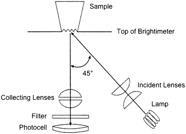
Schematic diagram of the light reflectance unit 62
Compositional analysis
Spectroscopic methods
Fast neutron activation analysis (FNAA), glow discharge mass spectroscopy (GD-MS) and glow discharge atomic emission spectroscopy (GD-AES) have been used to determine the chemical composition of Mg melts.
In the FNAA method, the samples are irradiated with 14·8 MeV neutrons and the reaction product ( 16 N) is detected. The number of 16 N atoms detected directly corresponds to the number of oxygen atoms in the sample. 56,63,64
In glow discharge source techniques, the sample is exposed to an argon plasma which uniformly erodes material from the sample surface. The sputtered atoms are ionised in this plasma and extracted into a mass spectrometer for separation and detection in GD-MS. In the case of GD-AES, a spectrometer is used to measure the wavelength and intensity of the light emitted by the sputtered atoms when they return to the ground electronic state.
FNAA, GD-MS and GD-AES have low detection limits (0·1–10 ppm) and high accuracy (5–20%). However, these methods all involve sample preparation, are time consuming, and require sophisticated and expensive instrumentation. 35,58 In addition, the FNAA method requires a neutron source such as a nuclear reactor, which usually is not accessible. Also, there is no industry specification for acceptable levels of oxygen in the samples and there is no exact correlation between the oxygen content within the sample and the oxide content. 35,58 Finally, these methods do not provide information on the inclusion size and morphology.
In arc spark emission spectroscopy, a voltage arc at the surface of the sample forms a plasma and the radiated light is collected and analysed. However, wavelength limitations make the measurement of oxygen difficult. Also, the sensitivity is limited to about 200 ppm. Finally, since the sample analysed is relatively small, the results may not be representative. 63
Laser induced breakdown spectroscopy (LIBS) has recently shown a potential for rapid qualitative and quantitative chemical analysis of various materials. 65 This technique is characterised by its rapidity, non-contact optical nature and its absence of sample preparation and is suitable for online measurements. It uses the light emitted from a laser generated plasma to determine the composition of a sample. Figure 7a shows a map of oxygen in a Mg sample obtained by LIBS. Comparison with an optical micrograph (Fig. 7b ) revealed that the darker feature seen in LIBS mapping corresponded to oxide inclusions. LIBS can thus be applied to locate inclusions in Mg samples.
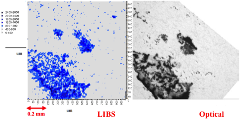
a LIBS mapping of oxide inclusions in magnesium samples and b corresponding optical micrograph 65
Matrix dissolution technique
In the matrix dissolution technique, the metal sample is dissolved in acid, bromethanol or methanol, leaving a residue of inclusions. The dissolution of a suitable sized sample (e.g. 30 g) takes up to 1 week. Inclusions are measured and quantified by means of optical microscopy, SEM/EDS, X-ray fluorescence or Coulter Counter technique. 35,66
In recent years, a method for Mg melt cleanliness assessment, based on wet chemistry, was developed (MagOxide). 58 It allows the quantification of MgO and Al–Mn intermetallics in pure Mg and Mg alloys. It is based on chemical dissolution of the Mg matrix and subsequent analysis of MgO residues by inductively coupled plasma emission spectrometer. However, the samples are only 2–3 g and may not be representative of the whole melt.
Other methods
Radiography
Radiography can be used to detect inclusions in Mg alloys, based on the difference in X-ray absorption between the Mg matrix and the defects. However, the difference in the absorption coefficient between Mg and its oxide is relatively small. As a result, an oxide skin is very difficult to detect. Also, only oxide inclusions having a minimum thickness equal to about 10% of the sample thickness can be detected. For flux inclusions, the detection limit is approximately 2%. 1
Liquid metal cleanliness analyser (LiMCA)
The LiMCA instrument offers on-line measurement of non-conducting particles. The LiMCA technique was developed based on the electric sensing zone principle. A schematic of the LiMCA instrument is shown in Fig. 8. The unit includes a probe, current source and signal processing system. The probe consists of two electrodes and an electrically insulating sampling tube with an orifice through its surface. Molten metal is drawn through the aperture in the presence of a large DC current. Non-conducting inclusions in the melt are detected by measurement of the change in the electrical conductivity as they pass through the aperture. 31,35,67,68
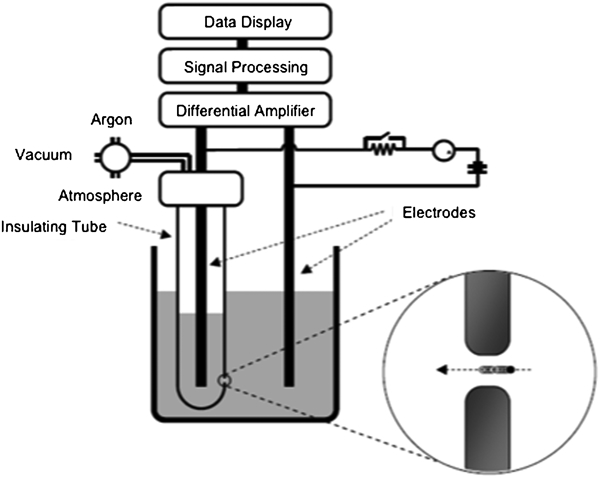
Schematic of the liquid metal cleanliness analyser technique 78
The LiMCA technique can be made available online very quickly at time intervals on the order of 1 min and is able to detect inclusions as small as 20 μm. However, this method presents several disadvantages: (1) it cannot detect conductive inclusions such as intermetallic particles, which are present in molten Mg; (2) the orifice can be blocked by large size inclusions; (3) the amount of molten metal that the LiMCA can assess at a time is very limited; (4) it fails to provide information on the chemistry, shape or the physical state of the inclusions; (5) there are difficulties in finding appropriate nonconductive materials for sampling tubes that are also non-reactive with Mg alloys; and (6) the cost is very high. 31
LECO method
The LECO method (oxygen and nitrogen determinator) may be applicable for detecting total oxygen and nitrogen in solid Mg samples. The method is based on fusion of a solid metal specimen in a graphite crucible. At high temperatures (up to 2300°C), magnesium oxide will be reduced to magnesium and carbon monoxide (CO) in the presence of carbon. The amount of CO developed can be quantified and related to the original MgO content. 69 The detection limit is claimed to be 0·1 ppm for both oxygen and nitrogen. 35 Large inclusions may affect the results, as the sample size is only about 1 g.
Ultrasonic methods
Ultrasonic methods have been reported as online methods to monitor molten metal properties. 31 A schematic of an ultrasonic apparatus is shown in Fig. 9. During measurement, a signal is sent through the melt by a transmitter and collected by a receiver. If there is no inclusion, the signal will propagate in the melt without much attenuation. However, the signal energy will be reduced when it is reflected at inclusions.
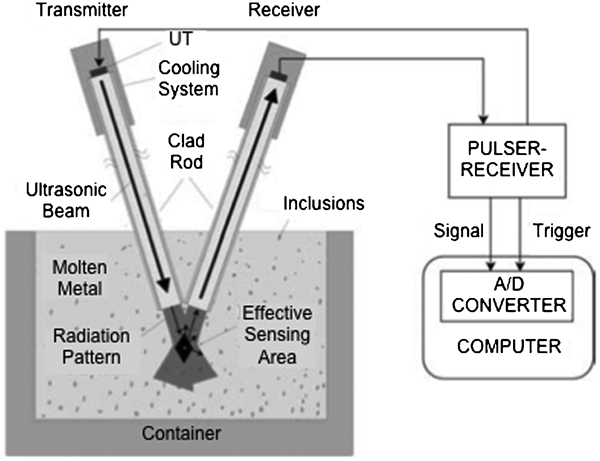
Schematic of an ultrasonic apparatus (UT: ultrasonic transducer) 70
Experimental results show that it is possible to use ultrasound to measure oxide content in molten Mg. This technique is capable of detecting both non-metallic and intermetallic inclusions. However, only inclusions larger than 100 μm are detectable due to limitations in sound frequencies generated by piezoelectric crystals. 31,70 Substantial development is still needed to implement this technique for Mg alloys.
Chen and Wei 71 proposed an ultrasonic vibration method for the diagnosis of oxide films entrapped in cast Mg alloys. The method is based on the phenomena of acoustic cavitation. A polished solid Mg sample is placed inside an ultrasonic cleaner filled with water. The ultrasonic sound waves generate cavitation bubbles, which in turn can produce microjets and shock waves and erode the surface of the sample. Oxide films then become visible as foggy marks on the surface of the sample.
Conductivity measurement
Electrical conductivity measurements are a fast and sensitive means of non-destructive evaluation that offers the potential of detecting the electrically insulating oxide particles embedded in the conductive Mg matrix. 72 However, it was found that electrical conductivity was very sensitive to the Al level and the amount of porosity in Mg alloys. As a result, electrical conductivity measurement cannot be used to measure the inclusion level in Mg samples.
X-ray tomography
X-ray computed tomography is a non-destructive technique which can be used to obtain 3D information on a sample structure, e.g. the size, shape, connectivity and spatial relationship between the inclusions in the castings. 73 X-ray computed tomography uses X-ray tubes, 73 although a synchrotron can also be used as a X-ray source. 74 Inclusions and precipitates in Mg alloys appear as regions of darker contrast than the Mg matrix with rod-, plate- and flake-like morphologies. 74 The limitations of this technique are its relatively high cost, long processing times and, if applicable, limited accessibility to a synchrotron.
Control of inclusions in magnesium alloys
Inclusions can be minimised by the application of best practices in the foundry. These include strict attention to charge selection, melting conditions, careful skimming of slag or dross, development and improvement of gating system design to minimise turbulence and process control (e.g. temperature control to minimise the precipitation of intermetallic particles and good settling practice). The inclusion content in the melt can be further decreased by refining techniques (cleaning or separation of nonmetallic inclusions from the melt) or alloying additions. These are described in the following sections.
Addition of flux
In flux based refining, the melt is heated to approximately 705°C, a flux is added and the melt is stirred thoroughly. The flux absorbs the oxides present in the melt to produce a sludge. After stirring, the sludge is allowed to settle to the bottom of the crucible, thereby enabling the refined melt to be separated from the sludge. Typical fluxes used in Mg refining are composed of magnesium chloride MgCl2, other chlorides (e.g. potassium chloride KCl, sodium chloride NaCl) and calcium fluoride CaF2. 1 Recently developed fluxes can also contain up to 30 wt-%TiO2. The added TiO2 facilitates Fe removal in melts by forming Ti–Fe compounds that settle at the bottom of the crucible. 30
The actual composition of the flux, however, will depend to a large extent on the type of Mg alloy to be refined. The Gibbs free energy of formation for some chlorides is shown in Fig. 10.
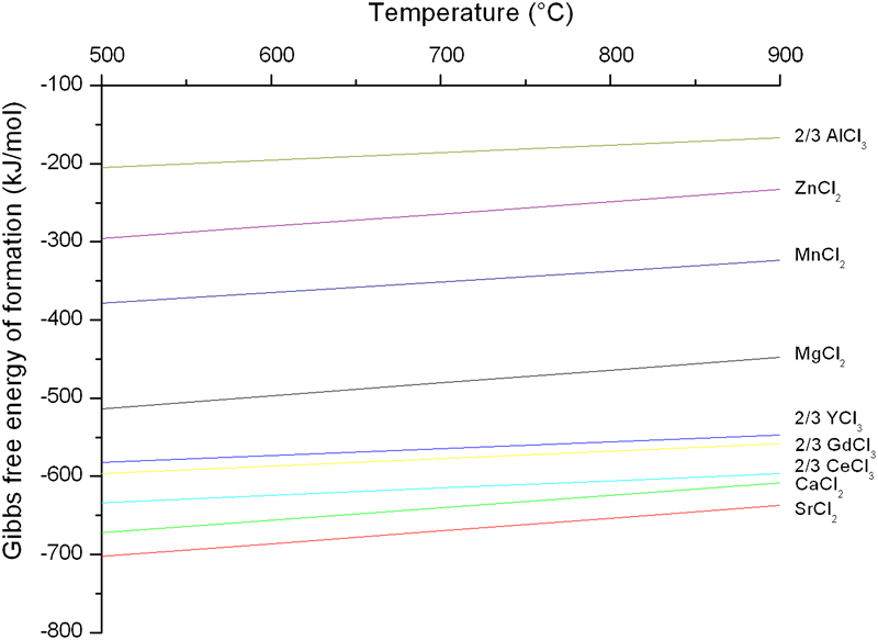
The major alloying elements (Al, Zn, Mn) are stable in the melt.
14,41
However, it can be seen that strontium chloride SrCl2, calcium chloride CaCl2 and chlorides containing rare earth elements RE (YCl3, CeCl3, GdCl3) are more stable than MgCl2. This indicates that the magnesium chloride in the flux should react with Sr, Ca and rare earth elements, resulting in the loss of these elements. The reactions are shown below:


Fluxless refining
Flux free refining includes all refining processes where salt is not used. Inclusions are removed from the bulk melt and transferred either to the melt surface, settle to the bottom or stick to the crucible walls before casting. 69 Fluxless refining processes are based on sedimentation (settling), floatation, interception or electromagnetic forces.
Protective atmospheres
Protective atmospheres 43–52 are used to prevent oxidation or burning of molten Mg and consequently to reduce the formation of inclusions in the melt. There are two types of protective gas atmospheres: 88 non-reactive gases and oxide film modifiers.
Non-reactive gases, such as nitrogen and argon, prevent burning. However, use of such gases is impractical outside of the laboratory as they do not suppress Mg vaporisation which can result in melt loss. In addition, as Mg vaporises, it condenses into pyrophoric size particles on the cooler surfaces of the furnace. 39
The other method of melt protection involves the use of a gas which modifies the magnesium oxide film forming naturally on the surface of the melt, thereby suppressing vaporisation. Since the 1970s, the Mg industry has largely used sulphur hexafluoride (SF6) to protect Mg melts. 39,43,44,51,88–93 Sulphur hexafluoride is an effective cover gas due to its ability to form a dense film containing Mg oxide (MgO) and Mg fluoride (MgF2) on the molten Mg surface. This film prevents further oxidation and evaporation of Mg. 43,44,93 Sulphur hexafluoride is also attractive as a cover gas since it is odourless, colourless, non-toxic, non-flammable and non-corrosive. It has been found that a combination of SF6 and CO2 is better than SF6 alone for pure Mg and most Mg alloys. The optimum SF6 concentration is 0·1–0·2 vol.-% as an excess concentration of SF6 will cause severe crucible corrosion. 39 However, SF6 is becoming increasingly expensive and is also an extremely powerful greenhouse gas, with a 100-year global warming potential, estimated at 23 900 times that of carbon dioxide (CO2). In addition, SF6 is chemically stable in the atmosphere and remains present for over 3200 years. 94
Environmental concerns have thus prompted the Mg industry to seek alternatives to SF6. Sulphur dioxide SO2 (approximately 1·5% in air) was demonstrated to adequately protect molten magnesium. However, SO2 is a toxic gas causing corrosion of foundry equipment. 92 Experiments also proved that pure CO2 effectively protects molten Mg, as long as the CO2 atmosphere is not contaminated with substantial quantities of air. 92
Other potential alternatives include HFCs, 45,48,50,52,95,96 FKs, 49 boron trifluoride BF3 97 and solid CO2. 98,99 Hydrofluorocarbons, which include HFC-134a (1,1,1,2-tetrafluoroethane C2H2F4), 48,50 HFC-152a (1,1-difluoroethane C2H4F2) 52 and HFC-125 (pentafluoroethane C2HF5), 96 have global warming potentials 8·5–170 times lower than SF6. The protection mechanism is similar to that of SF6 with the formation of MgF2 and MgO. 45,95 Boron trifluoride (BF3) is not a greenhouse gas and is well known for its excellent protective behaviour. However, BF3 is highly toxic and expensive. Boron trifluoride must also be stored as a concentrated, highly compressed gas and, as a result, special storage conditions are required to minimise explosion hazard. The MagShield system was developed to enable safe distribution of BF3. Specifically, the gas was produced in situ by the controlled decomposition of KBF4. 97 Fluorinated ketones 49 have global warming impact similar to that of CO2. They thermally decompose on the molten Mg surface, producing MgF2 and CO2. They have provided protection at significantly lower concentrations than SF6. The use of CO2 ice pellets to protect magnesium was accomplished by injecting CO2 into the furnace chamber at high pressure by a specially designed nozzle. The CO2 pellets precipitate at the molten metal surface and reduce the tendency of magnesium to evaporate. Sublimated CO2 snow also causes the CO2 gas to expand and displace all oxygen from the bath surface area. 98,99
For all cover gases, care should be taken to ensure that the gases are free of moisture and a continuous supply of fresh cover gases is optimal.
Filtration of inclusions
One simple method to reduce the presence of inclusions in castings is to reduce metal turbulence during melt handling. 14,100 High melt turbulence increases the probability of entraining gases or oxide films during mould filling, introducing more inclusions into the casting. Incorporating filters into the casting process helps reduce melt turbulence by regulating metal flow. Filters must be inert, rigid, thermally stable and thermally shockproof. 101 Ideally, the filter should be placed in the gating system of the mould (closest location to casting) as determined by examining the filling of a Mg plate casting using a mould with a pyrex glass cover at a pouring temperature of 680°C. With all other conditions being constant, the melt velocity with no filter was 0·18 m s−1 and with a filter in the runner, 0·13 and 0·14 m s−1 with a filter at the gate. 102
There are three stages of melt filtration: 102
initial surge: metal enters the filter pores and brings the filter temperature up to the melt temperature
normal flow: the metal flow through the filter is constant
filter blockage: the filter becomes blocked and metal flow stops.
Ceramic foam filters (CFFs)
CFFs consist of several open cells arranged in foam-like structures. Ceramic foam filters are typically used to lower inclusion levels in liquid aluminium alloys and steels. In contrast, the performance of CFFs for Mg alloy melts has not been studied extensively.
Bakke et al. 103 studied the effect of CFFs on the level of inclusions in AZ91 alloy. The CFFs used in their study consisted of 68·2%Al2O3, 14·6%SiO2, 15·2%ZrO2, 1·3%TiO2 and 0·7% others (K2O, CaO, HFO2, Fe2O3 and MgO). Their results indicated that the filtration efficiency of the CFFs was very good. Griffiths and Lai 54 observed that CFFs in combination with a well designed gating system could reduce double oxide film defects (folded MgO films).
However, it was reported that CFFs have limited and controversial efficiency:
CFFs can react with Mg melt and contaminate the melt. 104,105 Wu et al. 105 studied the potential reactions between various CFF materials (MgO, Al2O3, ZrO2 and SiC) and AZ91 melt during filtration. The authors observed that molten Mg reacted with SiC filters to form Mg2Si phases. Under the solidification conditions studied, Mg2Si phases exhibited a Chinese script morphology, which could reduce the mechanical properties of the alloy. The formation of Mg2Si was confirmed by thermodynamic calculations, which also revealed that Mg melt would react with Al2O3 and ZrO2 but not MgO. In conclusion, only MgO CFFs were suitable for filtration purification of Mg melts
the CFFs’ adsorption ability for inclusions can be very poor. For example, thermodynamic calculations showed that Al2O3 filters cannot adsorb flux inclusions in the melt. This makes it difficult to eliminate inclusions with diameters below 20 μm and liquid flux inclusions. In contrast, MgO proved to have good adsorption ability 105
there is no means to determine the point where a filter becomes ineffective and needs replacement. 104
Stainless steel mesh filters
Stainless steel meshes are typically used for the filtration of Mg melts due to their relatively low cost, high availability and non-reactivity with Mg melts. Le et al. 106 used stainless steel filters of decreased pore size in AZ91+2 wt-%Ca alloy. They found that the finest mesh caused a reduction in the number and maximum size of the inclusions. Also, they determined that low pouring temperatures (∼700°C) reduced the oxidation potential of the melt and the inclusion levels. 106 Tardif et al. 107 also examined the use of knitted steel mesh filters to remove melt inclusions in permanent moulds. Two and four ply filter configurations were examined and were found to entrap mainly MgO and some Al–Mn–Fe intermetallic particles.
Wang et al. 108 also showed that using stainless steel filters was an effective method to purify Mg–Gd–Y–Zr magnesium melts. The results indicated that the average size and volume fraction of the inclusions were significantly reduced (56% for the average size and 76% for the volume fraction), as shown in Fig. 11.
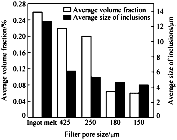
Effect of filtration on the size and amount of inclusions in Mg–Gd–Y–Zr magnesium alloy 108
Wang et al. 109 studied the effect of stainless steel mesh filters with various pore sizes on the melt cleanliness of AZ31 magnesium alloy. They observed that the use of filters proved to be an effective way to reduce the amount of inclusions in the alloy. The average size of the inclusions decreased from 16·5 to 2·0 μm.
Contradictory results were obtained by Emadi et al. 110 In their study, the use of steel mesh filters did not lead to a reduction in the amount of inclusions in AZ91D permanent mould casting, with consequent absence of improvement in mechanical properties.
Inert gas bubbling (sparging)
The refining method of gas sparging utilises an inert gas to float melt inclusions to the surface of the melt where they could be skimmed away. Typical gases used are argon (Ar) or carbon dioxide (CO2). The efficiency of gas bubbling to remove inclusions depends on bubbling time, gas flowrate, bubble size and melt temperature. 111 Typical usage of Ar gas sparging was a flowrate of 1·8 L min−1 at a melt temperature of 740°C for a bubbling time of 30 min. 111 With increasing bubbling time and/or flowrate, the rate of inclusion removal and hence, mechanical properties improved. Excess gas bubbling resulted in additional porosity in the melt that reduced strength and elongation. Argon bubbling was effective in removing inclusions less than 80 μm, but was unable to remove inclusions larger than 800 μm in size. 41 The limited availability of quantitative results on the efficiency of gas bubbling has sparked the need to determine the optimal processing variables (e.g., argon flowrate, residence time, bubble diameter, melt temperature) to enable efficient melt refining.
A combination of Ar gas sparging at 708 L h−1 and a stainless steel filter with openings of 1·14 mm (smaller openings were more prone to plugging and choking of metal) on recycled AZ91D Mg alloy filter has been shown to reduce the number of non-metallic inclusions/cm2 from 124 to 65 for the unfiltered and the filtered and bubbled melts respectively. 41 A similar result was observed with the simultaneous use of a 20 pores per inch (ppi) Al2O3 based ceramic foam filter and Ar bubbling by Wu et al. 112 . Argon was bubbled into the molten Mg using a rotary impeller and the optimum bubbling conditions were determined to be 2 L h−1 flowrate for 30 min at a melt temperature of 740°C.
Degassing
Melt degassing utilises typically reactive chlorine (Cl2) gas or hexachloroethane (C2Cl6) to reduce hydrogen gas content within melts. The addition of C2Cl6 has the added advantage of grain refining melts, but causes environmental problems due to the emission of chlorinated hydrocarbons. 113 Both methods benefit from the formation of MgCl2 (common flux component), which can remove inclusions as discussed previously, but may become an inclusion itself if it becomes entrapped within the melt during pouring. Typical usage of Cl2 gas bubbling involves heating the melt to 735–750°C and bubbling for 5–15 min. 12
Melt sedimentation (settling)
Various high density (4–7 g cm−3) Fe, Si and P based intermetallics can be removed from Mg by allowing them sufficient time to settle in the melt. 35 The required settling time depends on the size of the crucible, intermetallic particles and the type of holding furnace being utilised.
Ultrasonic purification
Ultrasound can be used to treat Mg alloy melt with the aim to enhance and accelerate the separation of inclusions from the melt. During ultrasonic treatment based on acoustic radiation forces, a force is exerted on the inclusions to promote their agglomeration and settling. Shao et al. 114 found that when ultrasound was applied, the inclusion fraction at the top layer decreased sharply from 80·6% to 3·3%, while it increases from 16·5% to 86·6% at the bottom layer. The result indicated that most of the inclusions suspended in the melt would ultimately sink into the bottom layer with the help of ultrasonic agglomeration. 114 The use of ultrasound to reduce melt inclusions is still in its infancy, but preliminary studies show much promise. Shao et al. 115 also examined the effect of ultrasonic power andparticle size on the efficiency of ultrasonic separation of inclusions. Their results revealed that there is anoptimum ultrasonic power above which no further improvement was observed. Also, at a given ultrasonic power, smaller particles take more time to agglomerate.
If the ultrasonic treatment is based on the formation of cavitation bubbles, high energy ultrasonic waves disintegrate large inclusion particles into finer, less detrimental particles more homogeneously dispersed in the Mg melts. 116
Electromagnetic separation
Electronic separation implies flotation of non-conducting inclusions in molten metal by electromagnetic force and their subsequent removal. This technique has been considered as a new technique to produce Mg melts free from inclusions. 117,118 Numerical simulations of steady state laminar flow of Mg in a vertical rectangular channel have shown that inclusion removal efficiency increases as current density increases and channel size decreases. However, the separation ability of the field diminishes as the velocity of the melt increases and further research is required to optimise the process. 117,118
Alloying additions
When Mg is melted in air, the oxide film that forms by reaction with the air is porous and unable to prevent catastrophic oxidation. Calcium and beryllium improve the protective quality of the reaction film, 39,,119 or increase the ignition temperature of the alloy Mg. Additions of CaO have resulted in a significant improvement in the oxidation and ignition resistance of Mg melts to the point where no protective gas was required during casting. 120,121 Although no melt cleanliness analysis was conducted, it is expected that a reduction of the oxidation potential could result in lower inclusion content in the melt.
Effect of inclusions on properties of magnesium alloys
There has been a lack of data on the effects of non-metallic inclusions on die cast Mg. 122 In this section, the data available are reviewed.
Tensile and fatigue properties
It is known that inclusions lead to premature failure of the material by reducing the effective cross-section of metal under load and by the concentration of stresses at the inclusion.
The direct impact of inclusions on the mechanical properties is, however, difficult to quantify, since casting defects such as cold shuts, hot tears and porosity will normally be present alongside inclusions and dominate over inclusions in determining the properties of a cast part. 28
This is illustrated in the work of Chen et al. 116 and Yim et al. 111 Chen et al. 116 studied the effect of ultrasonic treatment on the microstructural and mechanical properties of AZ91 and AM60 alloys. It was found that the application of ultrasound to the melt led to the fragmentation of oxide films. Inclusion particles became smaller, more numerous and better distributed in the melt. Smaller inclusion particles were preferable to the larger ones and should result in improved mechanical properties. However, gas pores and air pockets were also entrapped in the alloys during solidification, leading to a reduction of the UTS and the elongation.
Similarly, gas bubbling led to the removal of inclusions in AZ91D melt. 111 This was, however, accompanied by the formation of pores in the casting. Consequently, the tensile elongation of the alloy was found to decrease.
For defect free castings (hot tears, porosity, folds, etc.), the inclusion content and distribution of inclusions are assumed to be a critical factor in determining mechanical properties. 28 A significant improvement in the tensile properties (ultimate tensile strength and elongation) 30,41,62,81–84,86,102,107,108,122 and the impact strength 62,122 with the reduction of inclusion content in the melt was indeed observed by several researchers.
The stress–strain curves (Fig. 12) for AM50 alloy containing different levels of inclusions suggest that castings made using clean melts fracture at significantly higher strain than castings made using contaminated melts. 28 An inclusion level of 500 ppm was found to be the highest acceptable inclusion content.
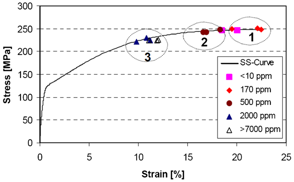
Effect of metal cleanliness on the mechanical properties of die cast AM50 28
Mirak et al. 53 showed that improving the running system design can lead to increased ultimate bend strength from 180 to 400 MPa, as a result of the reduction of the in-gate velocity from 1 to 0·25 m s−1. The Weibull modulus also increased with a reduction of the in-gate velocity, indicating decreased scatter of mechanical properties and improved reliability of the castings. This was attributed to a reduction of surface turbulence and double oxide films in the castings.
Elsayed et al. 124 observed that steel mesh filters with wire diameters of 0·4 mm and mesh size of 0·8×0·8 mm increased the mechanical properties of permanent mould cast AZ91E. Without a filter, the AZ91E alloy had an average yield strength, tensile strength and elongation of 93 MPa, 155 MPa and 2·26% respectively, which increased to 97 MPa, 167 MPa and 3·18% respectively with the use of a filter. The improved mechanical properties were attributed to the removal of oxide inclusions and the reduction of turbulence during casting.
Wang et al. 109 observed that the tensile properties of AZ31 alloy improved with the use of stainless steel mesh filters. The ultimate tensile strength and elongation of the alloy increased from 194 MPa and 13·8% to 212 MPa and 20·3% respectively.
Similarly, Tardif et al. 107 showed that melt filtration of AZ91 alloy produced consistently sound castings with improved tensile properties. Nazari et al. 102 and Griffiths and Lai 54 also showed that filtered castings exhibited higher Weibull moduli than unfiltered castings, indicating that the mechanical properties of the alloy were more consistent and reproducible.
Wu et al. 105,112 investigated the effect of filtration and gas bubbling on the ultimate tensile strength and elongation of AZ91. There was significant improvement in the UTS (10%) and the elongation (6%) with argon gas bubbling and filtration (Table 7).
Haerle et al. 62 obtained similar results. There was a further improvement of the mechanical properties when gas bubbling was combined with melt filtration, in agreement with Housh and Petrovich. 41
In regard to C2Cl6 addition, Emadi et al. 110 showed that without any pretreatment, the as cast yield strength, tensile strength and elongation of AZ91D alloy were 78 MPa, 176 MPa and 4·4% respectively. With the addition of 0·3 wt-%C2Cl6, the grain size decreased from 88 to 56 μm and the castings showed much fewer and smaller inclusions on the fracture surface. The yield strength, tensile strength and elongation increased to 92 MPa, 200 MPa and 5·1% respectively. In the case of AZ31 alloy, the yield strength, tensile strength and elongation were 52·0 MPa, 161·0 MPa and 14·5% respectively. When 0·2 wt-%CaO was added to AZ31, these properties increased to 74·9 MPa, 175·9 MPa and 18·0% respectively. 120 In both cases, the improvement in mechanical properties was attributed to both grain refinement and inclusion removal.
The addition of a C2Cl6–KCl mixture was also found to improve melt cleanliness of recycled AZ91E castings. 124 Upon remelting twice, the casting elongation reduced from 3·18% to 2·15% as compared to the virgin casting. The melt was cleaned of oxides with the addition of 1·0 wt-% C2Cl6–KCl mixture resulting in an improvement in mechanical properties and elongation. The casting after remelting twice had a tensile strength and elongation of 171 MPa and 2·15% respectively and increased to 195 MPa and 4·03% respectively with the addition of the C2Cl6–KCl mixture.
Researchers from Shanghai Jiaotong University performed several studies on GW103K (Mg–10Gd–3Y) type alloy. 81–84,86,108 They investigated the separate and combined effect of filters and various fluxes on the mechanical properties of GW103K. The use of fluxes resulted in the removal of inclusions in the melt, which in turn led to a significant increase in the ultimate tensile strength and elongation. Wang et al. 82 also studied the effect of MgO ceramic foam filters on the properties of GW103K. As compared to the untreated samples, the mechanical properties were higher but remained inferior to those obtained by using a flux, as the filter only removed large inclusions. In another study on Mg–Gd–Y–Zr alloy, the YS, ultimate tensile strength and elongation were improved from 156 MPa, 200 MPa and 3·4% to 167 MPa, 232 MPa and 7·0% respectively with the use of filters. 108 A similar study was performed on AZ91 alloy. 30 Again, it was found that the use of flux improved the mechanical properties of the alloy. The mechanical properties were further enhanced by combining the use of flux with ceramic foam filtration.
It should be noted that small oxide inclusions play a minor role in influencing tensile properties of castings. In a study by Wang et al., 123 the results indicate that oxide contents up to 1000 ppm levels have apparently no effect on tensile properties when most oxides are less than 15 μm and oxide films are less than 50 μm in size.
It is also accepted that fatigue life decreases significantly with inclusions size. In AZ91E alloys, Horstemeyer et al. 125 have shown that if the inclusion size is reduced from several millimetres to several hundred microns, the fatigue life in the high cycle fatigue regime can be increased by two orders of magnitude.
Fluidity
Inclusions can increase the viscosity of the melt, thereby impairing its fluidity. Also, if oxides are present, they have a tendency to form as films and these can block feeding channels and result in incomplete filling. 126 Bakke et al. 28 found that the flow length (measured using a meander die) of AM50 alloy was decreased by 10–20% in a contaminated melt. The reduction of inclusion content in the melt leads to an increase in the fluidity, as illustrated in Table 8. 58 Similar results were obtained by Wang et al. 82 and Wu et al. 127
Effect of MgO content on average fluidity length of AZ91 alloy measured using spiral shaped permanent mould 58
Corrosion resistance
Inclusions have a deleterious effect on the corrosion resistance of Mg alloys. 82–84,108,122,128 As an example, Wang et al. 82 studied the effect of inclusions on the corrosion rate of Mg–10Gd–3Y–0·5Zr alloy. They observed that the corrosion rate increased with increasing average volume fraction of inclusions, as shown in Table 9. This was attributed to the difference of electronegativity between the inclusions and Mg matrix. The inclusions act as cathodes and form galvanic coupling with the matrix, leading to pitting corrosion. With increasing inclusion content, the cathodic area increases, thereby adversely affecting the corrosion resistance of the alloy. 128
Effect of inclusion content on corrosion rate of Mg–10Gd–3Y–0·5Zr alloy 82
Machinability
Haerle et al. 122 studied the effect of non-metallic inclusions on the machinability of AZ91D alloy. They observed that a larger volume of inclusions contributed to a greater degree of wear of the cutting tools. As a result, the force required to cut AZ91D increased. The machinability of AZ91D was thus reduced.
Conclusions and perspectives
Types of inclusions and their control
Limited information on refining of Mg alloys is available, as compared to Al alloys. Inclusions present in molten Mg can be categorised into two major groups: non-metallic inclusions (mainly oxides and chlorides) and intermetallic inclusions (iron rich phases). These inclusions arise from various sources, which include the charge (quality of metals and alloys), melting process, reaction with fluxes and protective gases (during melting, transfer and pouring processes) and reactions in the mould. Several methods are available to control inclusions in Mg alloys.
fluxes, consisting of MgCl2 and other chlorides (e.g. KCl, NaCl), protect Mg melts from oxidation. However, typical fluxes used for the refining of Mg alloys are not compatible with all alloys, such as those containing calcium, strontium and rare earth elements.
fluxless methods include use of protective gases, filtration, gas bubbling and electromagnetic separation
addition of some alloying elements (e.g. calcium or beryllium) to Mg melts reduces the oxidation potential of Mg and consequently the inclusion content in the melt.
Melt cleanliness
Assessment of Mg melt cleanliness can be performed through physical measurement methods (FNAA, GD-MS and GD-AES). Though highly sensitive and accurate, these methods remain very expensive. Recently, techniques such as fracture surface examination, filtration of liquid metal and subsequent analysis of inclusions filtered, wet chemistry method, self-gravitation filtering technique and ultrasonic analyser have also been considered. However, there is no widely accepted criterion for testing Mg melt cleanliness.
Inclusions and properties
The use of filters, inert gas bubbling, fluxes and degasser addition are all effective methods to improve melt cleanliness and mechanical properties of Mg alloys. Improvements of 15% in tensile strength and 100% in elongation are possible. Combination of filtration and other techniques could further improve melt cleanliness and mechanical properties.
The presence of inclusions can also reduce melt fluidity and corrosion resistance of castings. The presence of inclusions will increase viscosity of melts making them more difficult to cast and form galvanic coupling with the matrix, leading to pitting corrosion.
The presence of non-metallic inclusions will also prematurely wear cutting tools and as a result, reduce the machinability of Mg alloys.
There is a need to understand and control all aspects of metal handling and processing to improve quality and consistency of the cast product.
Perspectives
Assessment of melt cleanliness
None of the techniques developed to assess the melt cleanliness of Mg alloys has been universally accepted. Metallographic techniques, humidity tests and K-mould fracture samples have been invaluable tools used in the foundry shop, but there is still a need for an efficient and economical assessment technique. A combination of methods may be needed. Future areas of research should aim at utilising filtration methods such as self-gravitation and HMIAM as these techniques are relatively easier to implement on a foundry scale and are of relatively low cost.
Control of inclusions
The methods used to control the inclusions in the melt need to be optimised, since some results are contradictory and quantitative results are missing. Most importantly, the process costs to achieve acceptable quality are sometimes prohibitive.
Understanding of inclusion formation and influence on Mg alloy properties
The majority of inclusion related issues with Mg alloys appear to originate with the molten Mg being exposed to moisture or oxygen. This is an issue during melting, melt transfer before pouring and mould filling. There is a need to determine the Mg melt quality at all stages of the casting process. Better understanding of the behaviour of oxide films (in particular bifilms) within the molten metal would help determine the best foundry practices to reduce their formation and entrapment in Mg melts.
Footnotes
Acknowledgements
The authors are indebted to Professor A. McLean for his review and valuable comments. They thank the members of the Centre for Near-Net-Shape Processing of Materials, in particular A. Machin, J. Hill, S. Ahmad and E. Vandersluis for their suggestions. They sincerely acknowledge the Natural Sciences and Engineering Research Council of Canada for financial support.