
Abstract
The raceway has been studied extensively both theoretically and experimentally. In this study, particle velocity contours have been developed to define the raceway boundary. The raceway boundary is coarse and fragmentised, but all of the previous studies are based on Euclidean geometry, which regard the dimension of the raceway as an integer. In this paper, the fractal method of calculating raceway size, which describes the boundary with extremely irregular or fragmented characteristics, is on the data from a cold physical model of the raceway. The results show that the precise raceway boundary can be obtained by the particle velocity contours, that the surface area of the ellipsoidal raceway based on fractal theory is larger than that based on Euclidean geometry and that the data can be used as original boundary conditions of the flow and chemical reaction in the raceway region.
Introduction
The raceway plays an important role in the distribution of gas flow in the ironmaking process, such as in the blast furnace and the COREX melter–gasifier. Thus, the raceway has great effect on the overall heat and mass transfer within the bed. For this reason, the raceway has extensively been studied both theoretically and experimentally.
Szekely and Poveromo1 and Nomura2 obtained the size of raceway according to a theoretical approach, which uses the derived formulae for the raceway based on a force balance. The study of Nomura2 shows that the raceway volume V
R is closely described by the product of depth D
R, height H
R and width W
R (i.e. V
R = 0·53D
R
H
R
W
R) and the relation between penetration factor (depth divided by tuyere diameter D
T) and raceway factor RF (i.e. D
R/D
T = 0·315RF
0·587). Moreover, many investigators1,3
–
5 have studied the size of the raceway using experiments, where the raceways are formed in room temperature ‘cold’ models. For example, Gardner3 found that the raceway depth D
R is related to the blast kinetic energy and the particle diameter, and the empirical correlation in a two-dimensional cold model is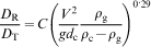
However, the size of the raceway is given only by a theoretical approach and the cold experiment. The shape of the raceway can be obtained by dissection survey and mathematical simulations.
Dissection surveys of the blast furnace have been performed by a number of scholars.6 – 8 In the study of Cheng and Zeng,6 the region of the raceway in the state of operation was preserved successfully by making use of injection and filling methods. The vertical section of the preserved raceway resembled an ellipse with the major and minor axes equal to the depth and height of the raceway respectively. Mathematical modelling has been undertaken for the gas and solid flows and the chemical reaction in and around the raceway region.9,10 Toshihiko et al. 10 calculated the instantaneous velocity of every particle through computational fluid dynamics plus discrete element modelling, and the raceway boundary was defined by the iso-contours of the instantaneous coke particle velocity scalar.
Previous literature shows that only numerical simulations can give the whole physical parameter field (such as pressure field, stress field, temperature field, gas composition field, porosity field, particle velocity field, etc.) in the raceway zone; other methods only give a few measuring points.
In this paper, data from a ‘cold model’ are recorded by the use of a high speed camera; then, the particle velocity fields in the raceway are obtained through data analysis. The raceway boundary is determined by particle velocity contours. In fact, the raceway boundary is not smooth but is coarse and fragmentised. The fractal geometry proposed by Mandelbrot11,12 is specially applied to describe this kind of boundary surface with extremely irregular or fragmented characteristics. In this study, fractal theory is applied to study the raceway boundary as the boundary can be described precisely by fractal geometry, which is very important for the theoretical and mathematical modelling of the gas and solid flows and the chemical reaction in and around the raceway region.
Experimental
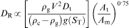
Based on the COREX melter–gasifier, a half section model was designed with scale of 1∶20. Figure 1 shows a schematic diagram of the experimental apparatus, including main apparatus, gas supply and gas distributor. The main part of this apparatus is a half section model made of transparent Perspex. Fourteen tuyeres are inserted from the sidewall with downward inclination angle of 4°. Polyethylene particles, 3·2 mm in diameter and 921 kg m−3 in density, are used as packed particles. These are charged into the half section model with a top hopper. Compressed air with moderate temperature is supplied by the gas cylinders through a gas distributor that makes the gas blowing rate uniform at each nozzle. The gas injected through the tuyere flows upward and out from the top of the model. The flowrate is measured with a flow meter corrected for any pressure effects.
Schematic illustration of melter–gasifier experimental apparatus
During the experiments, the semicircular model was filled with the particles to a required height above the tuyere. At the same time, a certain proportion of tracer particles in red were added to the charged particles. Next, the air flowrate was increased gradually from zero to the test flowrate. After 2 min, the raceway was regarded as stabile. Then, the pictures near the raceway zone on the front cover of the semicircular model were taken with a high speed photography at 512×512 resolution.
Digital image processing
Determination of raceway boundary
The pictures were taken at 100 frames/s in order to ensure that the shift of all the tracer particles in adjacent pictures is smaller than a particle diameter. The velocity and direction of every tracer particle, namely, velocity vector, is given by the following equation
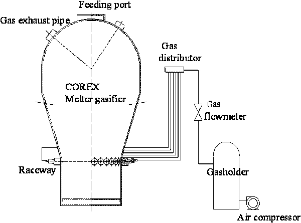
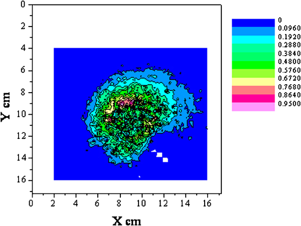
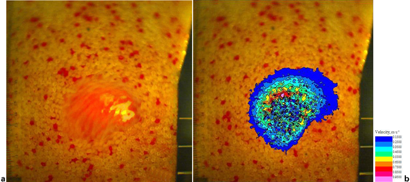
Figure 2 shows the trajectories and velocity of some tracer particles moving around the raceway boundary. When the particles are near the cavity of the raceway, the velocity is high. When the particles are away from the raceway, the velocity is relatively low. The particles that are in different positions could be treated in one picture during a time period. Thus, the particle velocity contour in the raceway can be obtained from sufficient measured data, as shown in Fig. 3. The particle velocity contours beyond 0·05, 0·1, 0·15 and 0·2 m s−1 are shown in Fig. 4. Comparing the original experimental picture in Fig. 5a with the particle velocity contours in Fig. 4c , the two are very close, as shown in Fig. 5b , so the particle velocity contour criterion of raceway boundary definition is 0·15 m s−1 in this paper.
Trajectories and velocity of typical particles moving around raceway boundary
Velocity and position of tracer particles during period of time in raceway
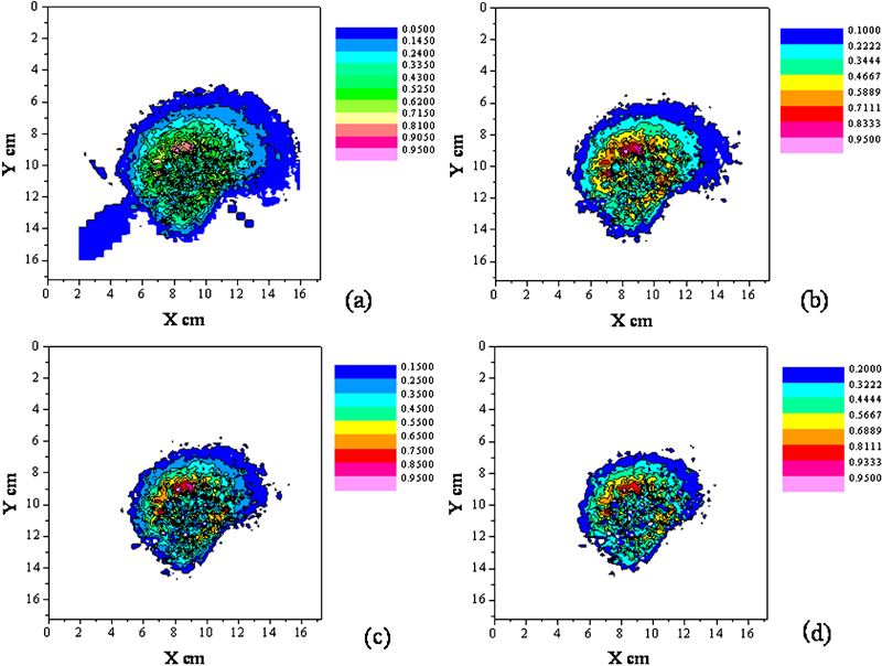
Raceway boundary definition using certain particle velocity contours
Definition of raceway boundary using particle velocity contour lines
Determination of textural fractal dimension
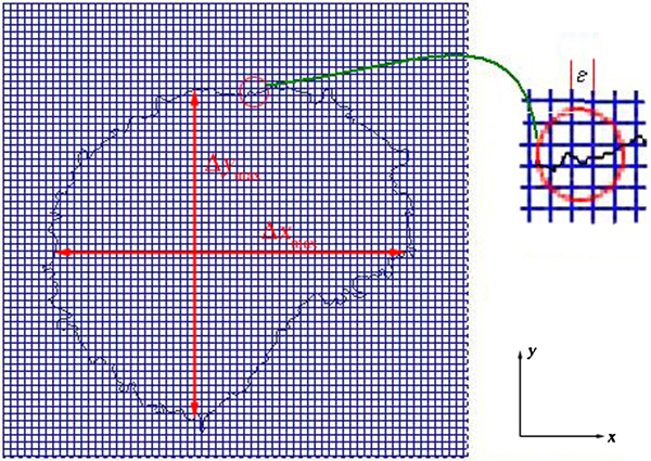
The precise raceway boundary shown in Fig. 5b
can be extracted as shown in Fig. 6. This figure shows that the raceway boundary is not smooth but coarse, so fractal theory is applied to study the raceway boundary. The textural fractal dimension is determined initially. The graphical analysis is shown in Fig. 6. The photography is space quantised by square with sides of ϵ (the unit is pixel), and then the number of squres N(ϵ) in the researched shape is counted. According to the mathematical definition of fractal dimension, there is
Boundary analysis
When the value of ϵ is changed, the group data of ϵ–N(ϵ) can be obtained. Plotting the data of ϵ−N(ϵ) in bilogarithm coordinates, the straight slope of ϵ–N(ϵ) is determined by linear regression. The straight slope is the fractal dimension D T.
Calculation of surface area of ellipsoidal raceway
During the processing of the experimental data, the raceway is regarded as a rotational ellipsoid with an irregular surface; thus, the raceway is regarded as the surface fractal geometry. Then, according to the law of additive codimensions,11,12 the surface fractal dimension D S is D S = D T+1.
The equation of the ellipsoidal raceway boundary is given as follows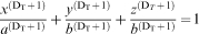


Suppose 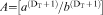
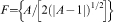
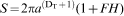
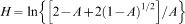
When a>b, the surface area of the ellipsoidal raceway S is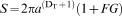

When a = b, the surface area of the ellipsoidal raceway S is
When b = 0, the surface area of the ellipsoidal raceway S is
Results and discussion
According to the process shown in Figs. 5 and 6, the raceway boundary under different blowing rates was obtained, and this is shown in Fig. 7. Through the aforementioned digital image processing and formula, the parameters of raceway under different blowing rates, which is based on fractal theory, were obtained, and the data are given in Table 1. The parameters of the raceway under different blowing rates based on Euclidean geometry are compared in Table 2.
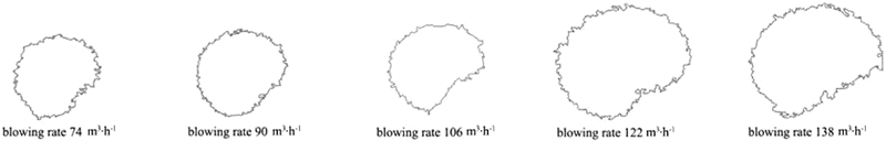
Raceway boundaries under different blowing rates
Parameters of raceway under different blowing rates based on fractal theory
Parameters of raceway under different blowing rates based on Euclidean geometry
Figure 8 shows that the surface area of the ellipsoidal raceway based on Euclidean geometry increased with increasing gas blowing rate, which is the same as the result of Gupta and Rudolph.13 When the blowing rate increases, the air pressure on the raceway boundary of particles increases (the direction of the air pressure being outward and normal to the raceway boundary), but the pressure which is due to the packed bed does not change. Therefore, the resultant force on the particles is outward normal direction of the raceway boundary and increases. Once the resultant force is greater than the particle–particle and particle–wall maximum static friction force, the depth of raceway increases and reaches a new steady state. In the experiments, when the blowing rate is >138 m3 h−1, the packed particles that are on top of the raceway float. As a result, the ellipsoidal raceway is damaged, which is consistent with the study of Zhang et al. 14
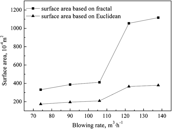
Surface area of raceway boundary based on fractal theory and Euclidean geometry
Figure 8 also shows that the surface area based on fractal theory is larger than that based on Euclidean geometry. The reason is that when fractal theory is applied, the surface area of the coarse part of the raceway is considered. The increment of surface area from the Euclidean geomety result to the fractal result when blowing rate is from 74 to 106 m3 h−1 is less than that when the blowing rate is from 106 to 138 m3 h−1. This can be explained by equation (6), where the difference from the Euclidean result is 
The surface area is very important for calculating the amount of heat and mass transfer. The ellipsoidal surface area, which is obtained by means of fractal theory, can supply precise area for research of raceway heat and mass transfer.
Conclusions
In this paper, particle velocity contours have been developed to process the experimental data in a cold model of COREX melter–gasifier. The raceway boundary can be defined precisely by the particle velocity contours.
Fractral theory has been developed to study the raceway size. By means of this method, the coarse and fragmentised raceway boundary can be studied precisely. It can be used as original boundary conditions of the flow and chemical reaction in the raceway region of the theoretical and mathematical simulation.
The surface area of the ellipsoidal raceway increased with increasing gas blowing rate. The surface area based on fractal is larger than that based on Euclidean.
Footnotes
Acknowledgements
This work was financially supported by the Fundamental Research Funds for the Central Universities (grant no. N090402021).