
Abstract
The technology of nail shooting was improved and used to study the transverse shape of the solidified shell during steel continuous casting. Three locations across the slab width (1/2, 1/4 and 1/8) were measured by nail shooting and which indicated a larger solidification coefficient and longer liquid core in the slab at higher casting speeds. The solidified shell across the slab width direction was non-uniform due to uneven secondary spray cooling. The point of final solidification at locations 1/8 and 1/4 was much longer than the position between the slab centre and location 1/4, leading to a long solidification end of >2 m, which is poor for the application of dynamic soft reduction. A mathematical model was developed to simulate the growth of the solidified shell and which was in good agreement with the measurements measured by nail shooting. Based on the measurements and simulations, the water spray pattern was improved, making the solidified shell more uniform. Dynamic soft reduction was then optimised resulting in reduced centreline segregation.
Introduction
During steel continuous casting, the progress of solidification significantly affects strand quality. Mathematical models1 – 3 are the most popular way to predict the solidification state of the strand; however, the reliability of a mathematical model depends in part on the accuracy of the boundary conditions, and inadequate models can lead to serious problems in industrial production. Therefore, the ability to measure the thickness of the strand solidified shell during casting will help calibrate mathematical models and improve understanding of the process.
There are many methods4 – 8 to measure the solidified shell thickness during steel continuous casting. These are summarised in Table 1. Kawawa et al. 4 introduced the technology of nail shooting in 1974 and Harris et al.9 and Normanton et al.10 reported studies on measuring solidified shell thickness using this technique. Nail shooting is one of the best ways to measure the thickness of the steel solidified shell, is easy to operate, and is reliable. Most studies4, 6, 11, 12 measured the shell thickness along the casting direction; however, due to non-uniform cooling, the solidification rate across the slab width often varies.13 Therefore, it is important to measure the solidified shell thickness across the slab width, so as to study the shape of the liquid core, which will aid in the determination of the reduction zone for the application of dynamic soft reduction technology.
Methods used to detect solidified shell thickness
In the current work, nail shooting was carried out at three locations across the width: locations 1/2 (slab centre), 1/4 and 1/8. The shape of solidified shell, the solidification coefficient, and the solidification end were then analysed. Numerical simulation was also carried out to compare with the measurements by the nail shooting experiment.
Description of nail shooting technology
Background
Sulphur is used as a tracer agent in nail shooting to measure the solidified shell thickness of the casting strand and can be carried in the steel nail in different ways. For instance, Jiang et al. 14 reported a tracer ring, in which the tracer was carried in a helical coil. In the current study, a grooved nail approach was used. Sulphur (in the form of iron disulphide FeS2) was carried in two slots in the steel nail, as shown in Fig. 1. During casting the steel nails were shot into the casting strand perpendicular to the surface by a nail shooting gun. The nails had sufficient momentum to penetrate the solid shell and the tips would melt in the liquid steel. In this way, the sulphur was quickly distributed into the molten steel. An example is shown in Fig. 2 where the steel nail lays across the solidified shell, the mushy zone and the liquid core. In the solidified shell, the strand temperature is not high enough to melt the steel nail. Therefore, the nail is in its original shape in Fig. 2a , and the sulphur is not diffused. In the liquid core (Fig. 2c ), the nail is totally melted and the sulphur is dispersed in the molten steel. The nail is partially melted in the mushy zone, as indicated in Fig. 2b . The solid mushy junction was taken as the location where the nail shape started to change/diffuse, as the line between Fig. 2a and b . The mushy liquid junction was the line between Fig. 2b and c , where the sulphur became well diffused and the nail shape almost disappeared. According to the morphology of the steel nail, the thickness of the solidified shell can be determined.
Schematic of nail shooting
Morphology of steel nail at different locations
Successful nail shooting experiments depend on correct installation of the nail shooting gun and loading of the steel nail. The steel nail needs to penetrate through the whole strand solidified shell, from the solid part to the liquid core, but not penetrate the full slab thickness.
Equipment and operation of nail shooting technique
Nail shooting equipment
As illustrated in Fig. 3, the experimental equipment used in the industrial plant included nail shooting gun, controller, explosive, steel nails, and the holding frame. The nail shooting gun and the steel nails are shown in Fig. 4. The length of the steel nails was 30–50 mm longer than half of the strand thickness. In this study, three shooting guns were controlled by one controller.
Equipment for nail shooting in industrial plant
Nail shooting gun and steel nails
Operating technique
Explosive force of the gun, strength of the steel nail, proper loading of the steel nail and the gun were all considered important to ensure the successful penetration of the steel nail through the solidified shell. Three kinds of shooting guns were prepared for the experiments: low explosive force, medium explosive force and high explosive force. The dimensions and strength of the guns, explosive and steel nails were varied. By considering the thickness and high temperature strength of the steel strand, guns with lower explosive force were tried first. For steel strands of <300 mm thickness, the shooting guns with low explosive force could be used. The steel nails were made of steel 60Si–2Mn.
The guns with high explosive force were designed for use on strands with thickness more than 600 mm or with higher strength steels.
Since the steel strand was at ∼1000°C the strength was much lower than the steel nails at room temperature, so it was not a problem for the nail to penetrate through the solidified shell. For those high strength alloy steels, such as high strength stainless steel, guns with higher explosive force might be needed on the same thickness. Another important issue was that the nails need to be melted in the liquid core of the strand, and thus, the melting point of the nail needed to be lower than the steel strand. Generally speaking, the carbon level in the nails should be higher than that in the steel strand.
Proper loading of the steel nail in the shooting gun is also very important for the successful penetration of the nails through the solidified shell. The nail needs to be properly loaded and be able to freely fly out of the gun perpendicular to the strand surface.
In the current study, regular steel slabs with thicknesses of 240 and 170 mm were tested. First, the guns with low explosive force were tried, and it turned out to be good enough for the measurement. The nails were shot into the strand and were lying at the expected locations. Therefore, three shooting guns with low explosive force were used in the current experiments. Three guns were shot at the same time so as to get the thickness of the solidified shell under the same conditions.
Experimental
In order to study the shape of the slab liquid core at the solidification end point, knowledge of the variation of the solidified shell along the width direction is important. In the current study, the solidified shell thickness at three locations along the width direction, including the locations 1/2 (slab centre), 1/4 and 1/8, were measured, as shown in Fig. 5. Initially the measuring points were 13·67 m away from the meniscus. The solidified shell thicknesses of steels A36 and D36 were measured under different casting conditions, and then, based on the results, the testing positions were reset and the solidified shell thicknesses of steels Q235A and A32 were measured under different conditions. Tables 2 and 3 illustrate the operating parameters of the caster and the measuring locations.
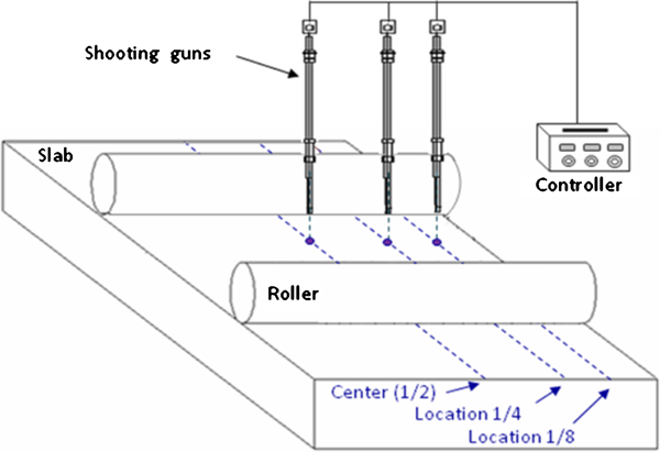
Measuring locations in nail shooting experiments
Caster details
Operating parameters and measuring locations
The positions of nail shooting were marked and, after cooling to the room temperature, the slab with steel nails was cut into samples (60×60×240 mm or 60×60×170 mm), and the thickness of solidified shell was determined by analysing the morphology of the steel nails. The success rate of nail shooting experiments was ∼75%.
Results and discussion
Shape of slab solidified shell measured by nail shooting
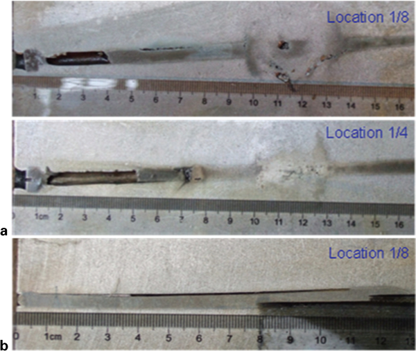
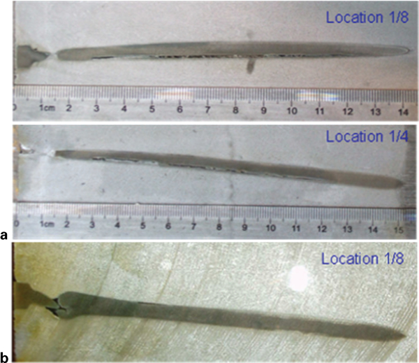
The thicknesses of solidified shells for slabs A36 and D36 at 13·67 m away from the meniscus are shown in Figs. 6 and 7. In the experiment of steel A36 at a casting speed of 0·87 m min−1 the steel nail at location 1/2 failed to go into the slab.
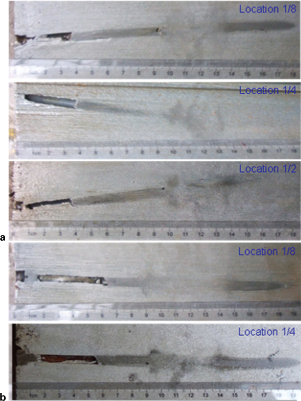
Photos of samples A36 with steel nails
Photos of samples D36 with steel nails
Since the slab temperature is ∼1000°C near the measuring point, the contraction of the slab during cooling cannot be ignored. The slab thickness at the test point was designed to be 240 mm, but only 236 mm at room temperature. Therefore, the thickness of solidified shell measured at room temperature needed to be calibrated to that at the test point. The thermal expansion coefficient of steel 60Si–2Mn (Fig. 8) at different temperatures was tested with a dilatometre DIL402C. The thermal expansion coefficient of steel 60Si–2Mn at 1000°C was ∼1·56×10−5 K−1. Then the solidified shell thickness at thermal state (∼1000°C) can be obtained by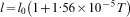
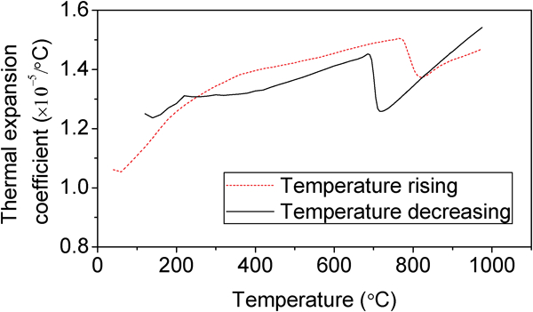
Thermal expansion coefficient of steel nails (60Si2–Mn)
The measured thicknesses of solidified shells at different operating conditions for slabs A36 and D36 at 13·67 m away from the meniscus are shown in Table 4 and Fig. 9, indicating thicker solidified shell at a slower casting speed. The results showed a non-uniform shell across the slab width due to the uneven secondary spray cooling. The lowest cooling intensity appeared at location 1/8, which was ∼200 mm away from the slab narrow faces, resulting in the thinnest shell thickness. The solidified shell between the locations 1/2 and 1/4 grew faster than the other parts because of the strongest secondary spray cooling. Therefore, location 1/8 had the smallest growth rate of solidified shell, and it is the final solidified location point.
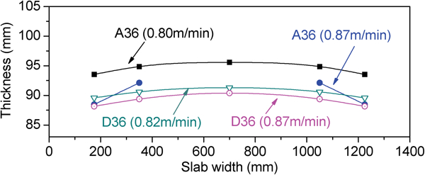
Thickness of solidified shell under different conditions for slabs A36 and D36
Measured thickness of solidified shell for A36 and D36
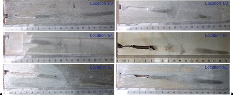
Since the thickness of solidified shells was still small at 13·67 m away from the meniscus, the measuring positions were reset to 15·71 and 20·35 m away from the meniscus. At 15·71 m the shooting guns were set at locations 1/4 and 1/8, the first and final solidified locations. At 20·35 m away from the meniscus, only one shooting gun was set at location 1/8. Owing to a change of production plan, slabs Q235A and A32 in different dimensions were tested in the experiments (as shown in Table 3). The photos of the samples with steel nails under different conditions are shown in Figs. 10 and 11, indicating that the steel nails were not melted in the slabs with a thickness of 170 mm, i.e. all the slabs were totally solidified before 15·71 m. The measured results were summarised in Table 5. For slab Q235A with 240 mm in thickness, the solidification end at the casting speed of 0·82 m min−1 was between 15·71 and 20·35 m. The results indicated again that the solidified shell at location 1/4 grew faster than that at location 1/8.
Photos of samples Q235A in 240 mm thick: v c = 0·82 m min−1
Photos of samples in 170 mm thick at 15·71 m away from meniscus: v c = 1·25 m min−1
Measured thickness of solidified shell for Q235A and A32
Discussion of solidification end point
The thickness of strand solidified shell during continuous casting can be expressed by
After being shot into the strand, the steel nail will be melted and the sulphur will diffuse in the molten steel. There is, therefore, a short delay before diffusion starts which could alter the solidification time estimate. Han and Chen15 reported a method to correct the solidification time, which considers the melting time and moving time of the steel nail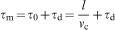
With the measured thickness of solidified shell, the modified integrated solidification coefficient K can be calculated by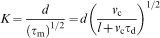

Putting equation (4) into equation (5), the distance from the meniscus to the solidification end can be calculated by
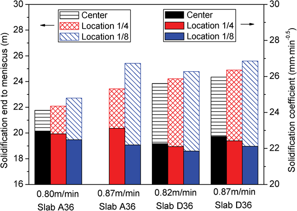
Comparison of measurements under different conditions
Solidification end point and solidification coefficient for A36 and D36
Solidification end point and solidification coefficient for Q235A and A32
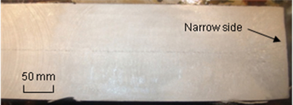
Owing to the different solubilities of alloy elements in the liquid phase and the solid phase, the segregation solutes would precipitate in the liquid core. Therefore, serious macrosegregation would occur at the final solidified locations.13 Figure 13 indicates much more macrosegregation near the location 1/8 (the final solidified location) in the industrial slab, validating the accuracy of measurements obtained by the nail shooting.
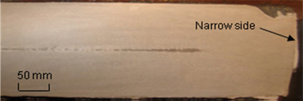
Macrosegregation in industrial slab
With the irregular liquid core and long solidification end, the dynamical soft reduction technology is difficult to apply effectively during casting, hence the distribution of secondary spray cooling across width direction needed to be made more uniform so as to eliminate the non-uniform growth of the solidified shell and to improve the slab quality.
As the nail shooting process was found to be accurate enough for industrial use, and the position and shape of solidification end have been determined, the reduction area for dynamic soft reduction model was optimised. After the optimisation, the slab centreline segregation was significantly improved (Fig. 14).
Slab quality after improvement of dynamic soft reduction model
Comparison between measurements and simulation results
Based on the caster cooling system, a mathematical model16 was developed to simulate the growth of the solidified shell during the casting of slab D36. The variation of cooling intensity along both width direction and casting direction was considered in the simulation. The solidification of slab D36 at a casting speed of 0·82 m min−1 was simulated. The comparison between the measurements from nail shooting and the simulation results is shown in Fig. 15, indicating good agreement. By using the measured thickness of solidified shell, the distance from the solidification end to the meniscus was calculated by equation (6). The results agreed well with the simulated results, as shown in Table 8. The average relative error was 1·74%.
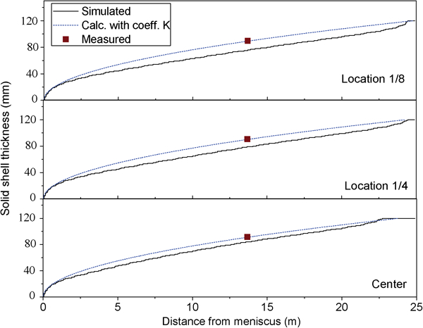
Comparison between measurements and calculated results
Comparison between measurements and calculated results
The measured lengths of liquid cores were calculated by the solidification coefficients obtained from the measurements.
The shape of slab solidified shell at the cross-section calculated by the mathematical model is shown in Fig. 16, indicating faster shell growth at the locations between the slab centre and location 1/4 where the spray cooling was stronger. Owing to the non-uniform distribution of secondary spray cooling across the width, the solidification between location 1/4 and slab centre completed first, and the liquid core was divided into three parts: slab centre and the two parts ∼200 mm away from the narrow faces, as illustrated in Fig. 16b . The final solidification locations of the slab were between locations 1/8 and 1/4. The distance from the final solidified region to the first solidified region was >2 m.
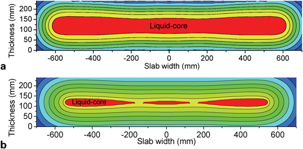
Simulated shape of slab solidified shell at cross-section
Conclusions
The technology of nail shooting was studied and further developed to measure the transverse shape of the solidified shell during slab continuous casting. Conclusions are summarised as follows.
For steel strands less than 300 mm thick the shooting guns with low explosive force could be used. A satisfactory method was developed.
From the nail shooting experiments the solidified shell shape was determined.
Due to uneven spray cooling, the shape of the shell was non-uniform across the slab width. The locations between slab centre and location 1/4 solidified first. The final solidification end appeared between location 1/8 and location 1/4. The length of solidification end was over 2 m, which is bad for the application of dynamic soft reduction technology.
A mathematical model was developed to simulate the shape of slab solidified shell. The numerical simulation was in good agreement with the measurements obtained by nail shooting. The average relative error was 1·74%.
Based on the measurements and simulations the water spray pattern was improved, making the solidified shell more uniform. Dynamic soft reduction was then optimised resulting in reduced centreline segregation.
Footnotes
Acknowledgements
The authors would like to thank the Natural Science Foundation of China (NSFC) for the financial support (no. 50774105).