
Abstract
Ultrathick continuous slab casting is a growing technology, especially in developing countries due to the vast market demand of thick rolled plate. The structure of the submerged entry nozzle is regarded as the crucial factor to determine flow related phenomena in the mould. This article conducts a 0·55 scale water model and a three-dimensional numerical model to investigate the influences of submerged entry nozzle on flow behaviour, temperature field and solidified shell distribution in a 420 mm ultrathick slab mould. Physical and numerical finite volume methods with K–ϵ turbulence model simulations verify that the flow pattern in ultrathick mould is similar with that in conventional slab mould. The diffuse type nozzle fails to increase the surface velocity while easily causing slag entrainment. The four-spout nozzle gives a detrimental effect on shell distribution. The tunnel bottom nozzle is optimal, because it shows a lively surface behaviour and a favourable heat transfer between mould flux and surface flow, and the shell thickness is uniform and thick enough at the mould exit to avoid breakout.
Introduction
Ultrathick plate as the main construction material has a wide range of uses in civil and military facilities, such as the gates of hydroelectric power stations, offshore platforms, the deck of the aircraft carrier, etc. Traditionally, directional solidification method1 – 3 and electroslag remelting technology4 were employed to produce ultrathick alloy or steel slabs. Recent continuous casting technology developments in the casting of ultrathick slab have resulted in thick plate being rolled directly from ultrathick slabs, with an added advantage in terms of high production capacity, excellent mechanical properties and surface quality.5 However, internal looseness and segregation and surface and subsurface defects in the slab may produce difficulties in the final plate. Therefore, a proper understanding of slab characteristics and influences given by the mould is of great importance for achieving satisfactory properties in the as cast slab. The submerged entry nozzle (SEN), whose geometry affects significantly the flow distribution and heat transfer pattern, is compared with the heart of mould. Specifically, since the nozzle controls the speed, direction and heat transfer of the liquid steel jetting into the mould, it has an overwhelming role in preventing problems such as unreasonable surface waves, meniscus freezing, crack formation and even breakouts.6
As shown in Table 1, there is a growing tendency for ultrathick slab continuous casting. The information of the 420 mm thick slab caster used for this paper is listed in Table 2. Because of the new application of ultrathick slab casters, the flow pattern and heat transfer mechanism in the mould have as yet not been investigated completely. Most of the previous works7 – 11 developed both experimental and numerical models for the analysis of flow behaviour and solidified shell distribution. However, those models w`ere confined to conventional geometry, in which the maximum thickness was <300 mm, such as billet, bloom and slab. Xie et al. 12 applied water modelling to evaluate the conventional SEN performance in a 420 mm ultrathick slab mould. Gupta and Lahiri13 compared flow differences in four aspect ratios of moulds, pointing out that the flow pattern was asymmetrical when the aspect ratio was larger than 1∶6·25. Wu et al. 14 simulated the shell thickness in a 240 mm continuous casting mould using a volume of fluid (VOF) model and found a zero increase in shell thickness in a certain range near the impingement point. Hershey et al. 6 compared the results from two- and three-dimensional simulations with specific SEN boundary conditions to investigate turbulent flow passing bifurcated nozzles, which would assist the SEN design. Hence, in order to obtain an optimised liquid steel flow strategy in the ultrathick slab mould, it is necessary to characterise diverse flow and temperature fields with different SENs so it can provide guidelines for producing this type of slab.
Data of ultrathick slab mould in world
Information of 420 mm mould apparatus
Water modelling and numerical simulation have been used a great deal by researchers15 – 19 all over the world to analyse completely and precisely flow patterns and heat transfer mechanisms in moulds. Based on the similarity principle, water modelling studied the actual mould process by testing measures to acquire operating parameters and improve numerical simulation, obtaining a good intuitive understanding. However, when facing temperature and shell thickness distribution, numerical simulation is far more advanced than that of water modelling because of its help in capturing the heat transfer phenomenon to guide and simplify physical simulation. Therefore, physical and numerical simulations play complementary roles to each other. Combining physical and numerical simulation is regarded as a reasonable method to investigate the flow behaviour in the mould.
The purpose of the present work is to illustrate flow field, heat transfer and shell thickness distribution in a 420 mm ultrathick slab mould and to find the optimal SEN structure. To do this, a 0·55 scale water model and a steady finite volume numerical simulation with standard K–ϵ turbulent model are used to compare a conventional SEN with three new designs.
Water model experiments
Ultrathick slab mould modelling
In accordance with Froude and Webber’s number similarity, which guarantees the similarities between prototype and model in geometrical size, kinematic viscosity and interface behaviour,20, 21 a 0·55∶1 plastic scale water model was set up to observe the flow field using dye poured from the inlet of the SEN.22 It is widely acknowledged that the variation of level wave has a profound effect on the flux/liquid steel interface as well as the meniscus behaviour.23 – 25 In this work, surface waves are quite different from that in normal size mould due to the large cross-section (420×2400 mm). A DJ800 multifunctional hydraulic monitoring system was applied to measure the level of the waves. Figure 1 shows the geometric dimensions of the water model apparatus and the positions of wave height sensors.
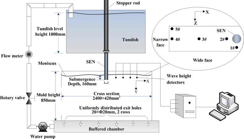
Schematic of water model apparatus
In the experiments, the casting speed was simulated at 0·55 m min−1, this being controlled by valve and flow meter. Wave height sensors were inserted 30 mm below liquid level, which was kept constant with the help of stopper rod in tundish. Data were collected and recorded every 0·02 s over the period of 164 s. Given that it would be very difficult to find regularities if the data collected are a group of irregular values, the 1/10 large wave was selected to process data mathematically. Wave heights were arranged in order from large to small, and the average of the top 1/10 wave heights was used as the 1/10 large wave; this reveals fluctuation features easily. Therefore, the 1/10 large wave was regarded as the measure to evaluate surface behaviour.
Submerged entry nozzle design
The configuration of the SEN is essential in optimising transient flow and heat transfer in the mould.8,26 – 28 The jet from the ports brings a specified amount of energy and impinges on the narrow wall, which, if it is not appropriate, will cause surface defects, slag entrainments and even breakouts. Therefore, it is the SEN and its impingement point that link the degree of active liquid surface and slab properties at the mould exit.
As a result of the large cross-section of the mould investigated in the present work, the upper circulation flow diffuses quickly, and the transmission phenomenon near nozzle and meniscus is weak. In order to enhance the degree of active surface and avoid freezing of liquid steel, a four-spout nozzle, a diffuse type nozzle and a tunnel bottom nozzle were investigated to obtain the optimum SEN; these, together with the conventional nozzle, are shown schematically in Fig. 2. Table 3 gives the parameters of the SENs and experimental conditions in this work.
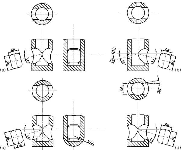
Schematic of SENs investigated
Characteristic parameters and experimental conditions of SEN
Figure 2a shows the design of the conventional SEN. The liquid level is quite near the nozzle area in the experimental condition, which is supposed to be a main reason to cause poor slag melting and slag ring formation. A four-spout SEN was designed with the expectation to accelerate the flow of liquid steel at the meniscus level. This SEN, based on the conventional SEN, had two little holes (port angle 15° and radius 12 mm) at both the front and back sides and is shown schematically in Fig. 2b . In addition, because the tunnel bottom could contribute to the flow near the nozzle, this could increase the level fluctuation and surface temperature. Therefore, a tunnel bottom SEN with a radius of 66 mm was also investigated in this work, as shown schematically in Fig. 2c . Its bottom had a defined radius, while the conventional SEN had a flat bottom. To avoid excessive temperature drop at the mould corner and improve the mass and heat transfer at the meniscus, a diffuse type SEN27 was developed to broaden the cross-section of the jets. Considering the fact that the jet velocity decreases with the increase in port area, the diffuse angle in this experiment was designed to 10° (as shown in Fig. 2d ).
Numerical model
Governing equations
The present work adopts a three-dimensional, steady state and single phase mathematics model with finite volume method to investigate the flow of molten steel from the various SENs.29, 30 The steel flow is treated as incompressible, viscous Newtonian fluid characterised by solving the conservation equations for mass, momentum and energy.31, 32
Mass equation
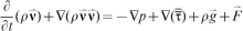


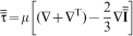

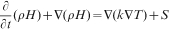
Energy equation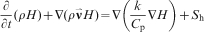

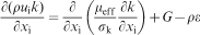
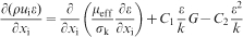
The classical K–ϵ turbulence model is selected to consider the transport of the turbulent kinetic energy K and the dissipation rate ϵ in turbulence flow in the mould.
Turbulent kinetic energy K
Solidification model
Based on a real production process, a solidification model was introduced in the present work to avoid the deviation brought by solidified shell and steel shell phase region.
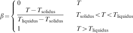
The commercial code FLUENT33 adopts enthalpy–porosity to deal with the solidification and melting process. The mushy zone, whose liquid fraction is between 0 and 1, is simulated by porosity through calculating the temperature of each element. In the solidification process, the porosity of the material declines with liquid fraction, and it reduces to 0 when solidification is completed; therefore, fluid velocity also reduces to 0.
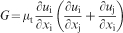
The loss of momentum is due to the reduction in porosity in the mushy zone, and a source item should be presented in the momentum equation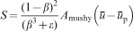


Boundary conditions
The larger flowing domain in the ultrathick slab mould results in the lower circulation flow extending well beyond the mould outlet. Thus, the computational domain was extended to 3000 mm in the present work to give a complete insight of flow movement; this made it possible to apply an outflow boundary condition at the mould exit. In a 1∶4 nozzle mould combined computational domain (shown in Fig. 3), another type of boundary condition had been also studied. The velocity inlet boundary condition was given to the entrance of the SEN, and V y was kept constant. The inlet temperature is assumed to be constant with the superheat 25 K. Symmetrical condition was employed at the X–Y and Y–Z symmetrical planes. Specifically, the free liquid surface was also treated as a symmetrical plane. The no slip boundary condition was considered at both wide and narrow walls.34 Both wide and narrow surface walls were divided into three sections (0–850, 850–1700 and 1700–3000 mm). The heat transfer coefficients loaded into each section of the narrow wall are 1100, 700 and 500 W m−2 K−1, and of the wide wall are 900, 600 and 500 W m−2 K−1 respectively.
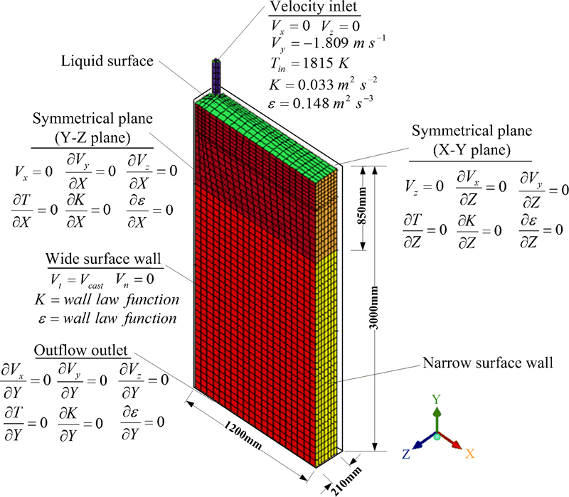
Grid and boundary conditions of computational domain
Computational details
Table 4 presents the parameter conditions and properties of the fluid in the simulation. For the rapid and accurate computation, the hexahedral mesh system was generated, and the orthogonal curvilinear grid was used to improve the mesh quality in a certain area near the ports. In the present work, the finite volume technique was used to discretise the governing equations, and then the SIMPLEC strategy was used to solve the governing equations. All these were integrated in the commercial FLUENT software. The discretisation scheme of momentum and K–ϵ turbulent model was first order upwind, while the scheme for the pressure algorithm is PRESTO. All models were computed on a personal computer with 1·80 GHz CPU and 2 GB of RAM. Each simulation was defined as convergence when all residuals declined below 10−4. The specific mesh and computing situations of four models are listed in Table 5. More information about equations (1)–(12) and details of the solution procedure are given elsewhere.18, 34 – 37
Parameter conditions and properties of fluid
Mesh and computing situations
Water model results
Flow pattern
Figure 4 shows the development of the circulation flow pattern in the water model over a 9 s period from the injection of the dye for the conventional nozzle. Obviously, there is little variance in mechanism of fluid flow movement between a conventional slab mould and the ultrathick one. Within the initial 3 s, the jet goes forward straightly with an angle larger than the port angle due to the gravity and diffusion. The left and right jet angles remain similar throughout the time and increase to 26° until the flow impinges at narrow walls. Over the next 3 s, a transient asymmetrical field (curves indicated in figure) is observed when the flow spreads further to cover whole narrow walls. During the next 3 s, the flow transfers one that is approximately symmetrical, and the upper and lower circulation zones were formed.
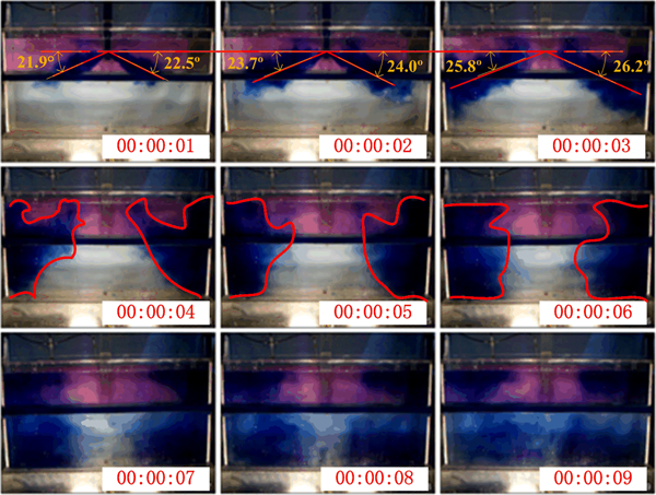
Main characteristics of flow field in ultrathick slab model with conventional SEN (colour version available online)
Level fluctuation
Based on former research,19, 38 the level fluctuation is regarded as an effective element to indicate surface velocity. The reasonable level fluctuation should be acquired to activate the mould surface but restrain the vortex that can cause severe slag entrainment.
Figure 5 compares the level fluctuation of the four nozzles at five measuring positions. At sensor position 1# (Fig. 1), the 1/10 large wave of the four-spout nozzle in the thickness direction is 2·0 mm, which is twice that of the conventional nozzle. However, the value reaches 2·8 mm for the tunnel bottom nozzle. Presented in Fig. 5b , the highest 1/10 large wave of 3 mm is still obtained by the tunnel bottom nozzle, whereas the other cases are all near 2 mm. Owing to the degradation of kinetic energy in both jet flow and back flow, the values for the tunnel bottom, diffuse type and conventional nozzles drop at the quarter of the mould, as shown in Fig. 5c . The narrow side witnesses the highest 1/10 large waves for all nozzle types. It is worthy to note that the values for the tunnel bottom nozzle fall within a reasonable range, and the wave distributions near the narrow wall for the diffuse type nozzle are more uniform than for the conventional nozzle, as shown in Fig. 5d and e respectively.
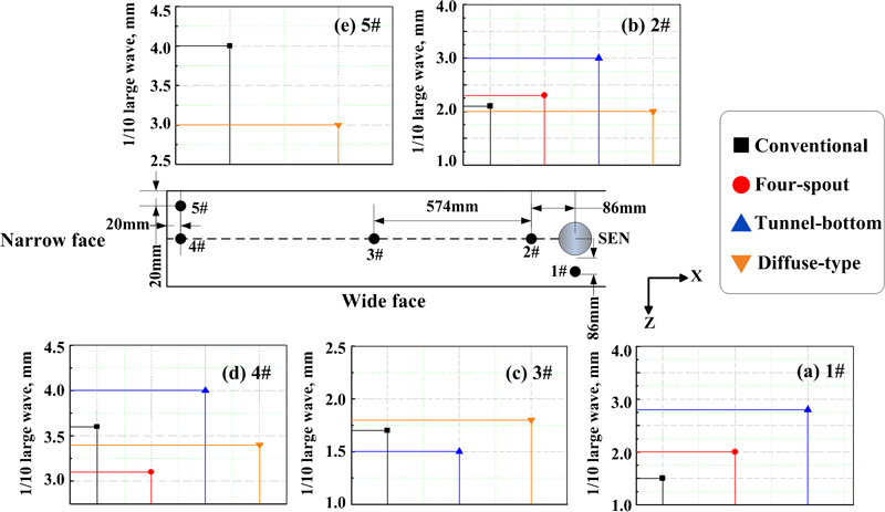
Level fluctuations and measuring positions for four SENs
The shunting effect of the four-spout nozzle plays a significant role in increasing the surface wave in the thickness direction; however, it decreases the velocity of jet from the main ports. In the diffuse angle nozzle, the diffuse angle allows the jet to expand, which reduces its velocity towards the narrow wall of the mould. This explains the reason that the wave is relatively small but distributes evenly at the area far away from the nozzle. Compared with the other three nozzles, the tunnel bottom nozzle is more favourable in controlling the surface behaviour in the ultrathick slab mould. As the streamline part of the tunnel bottom leads steel flow to the upper circulation zone, the velocity at the surface increases. On the contrary, the conventional nozzle suppresses liquid steel from lower to upper circulation zone. Therefore, on the water model, the tunnel bottom nozzle is beneficial to enhance the mass and heat transfer at the mould surface.
Slag entrainment
Mould powder covering the surface of liquid steel in the mould can prevent reoxidation and absorb non-metallic inclusions, but it is detrimental to liquid steel quality when the flow from the SEN entraps mould powder/flux. In the present experiment, mixed oil was poured into the mould to form an ∼10 mm liquid slag layer. By analysing the oil distribution, the influences of flow field on the mould powder were assessed qualitatively.
The kinematic viscosity of mixed oil was determined by the following equation: υ steel/υ slag = υ water/υ oil.
The physical parameters of water, liquid steel and mould powder are listed in Table 6. The kinematic viscosity of mixed oil in the experiment is (0·48–4·74)×10−4 m2 s−1, acquired by mixing various mechanical oils.
Physical parameters of water, steel and slag
The experimental results show that the diffuse type nozzle gives rise to serious slag entrainment; the frequency of slag entrainment is higher near the nozzle and the 1/4 position of the mould. Figure 6 shows the slag entrainment phenomena in the experiment. It suggests that diffuse type nozzle helps flow spread out and impinges at wide wall earlier, thus causing great flow exchange.

Slag entrainment at diffuse type nozzle area
Numerical simulation was employed to verify the slag entrainment in the diffuse type nozzle case. Figure 7 shows the vectors of the flow field 50 mm below the liquid level in the mould. The obvious downward flow near the nozzle causes vortexing to occur easily, which may lead to slag entrainment.
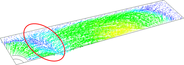
Vector diagram of flow field 50 mm below liquid level in mould with diffuse type nozzle
Numerical results
Flow pattern in nozzle
The flow patterns in the ports for the four nozzles are presented in Fig. 8, and Fig. 9 illustrates the positions of planes I, II and III in Fig. 8. Overall, as the flow bounces back after impinging at the nozzle bottom, the velocity decreases gradually from the port bottom to the top. The maximum velocity also declines from inside to outside of the nozzle port, except for the diffuse type nozzle.
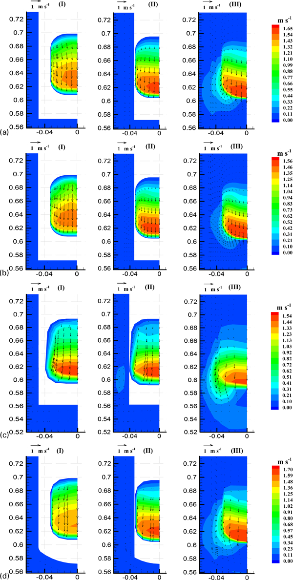
Velocity contours and vectors at I, II and III planes in and near nozzle ports with a conventional, b four-spout, c diffuse type and d tunnel bottom nozzles (colour version available online)
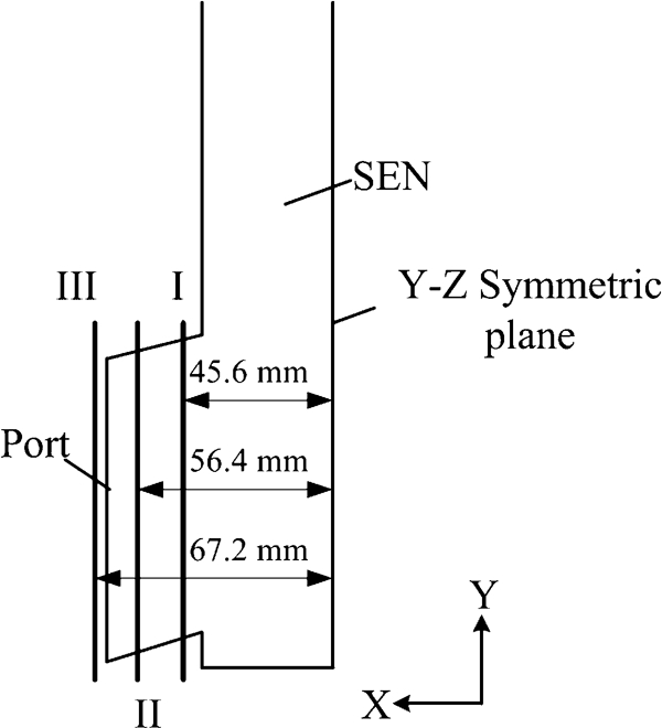
Schematic of positions of planes I, II and III shown in Fig. 8
Owing to the consistent structure of the ports in the width direction, a similar pattern is obtained in the conventional and four-spout cases, as shown in Fig. 8a and b , but in the thickness direction, the ports of the four-spout nozzle reduce the flowrate and causes lower velocity in the width direction. However, this slightly enhances the flow capacity near the nozzle area, as is shown in the velocity vector in plane III of Fig. 8b . The diffuse type nozzle, shown in Fig. 8c , gives the maximum area distribution of flow to the strand while having the minimum velocity near the port when compared with the other three cases. In the tunnel bottom case, as is shown in Fig. 8d , the streamline bottom leads to an increase in flow velocity to 1·704 m s−1, which indicates a stronger fluid flow in the upper circulation zone.
Measured by the weighted average, the jet characters of plane II in Table 7 agree well with those observed in Fig. 9. Considering port velocity and mass flowrate, the four-spout nozzle is relatively low due to the shunting effect. The maximum turbulent kinetic intensity and energy of the conventional nozzle indicates low frequency and high disorder flow near the port area. The tunnel bottom nozzle possesses an appropriate average velocity with moderate turbulent intensity, kinetic energy and dissipation, which is beneficial to reinforce the flow at liquid surface and reduce the possibility of vortex formation.
Computed jet characters of nozzle port
Flow pattern in mould
The flow patterns of the four cases are compared in Fig. 10. In all cases, liquid steel presents the classic ‘double roll’ pattern,39, 40 and at the area 1850 mm under the meniscus, the flow tends to be uniform, which is beneficial to maintain the continuous casting process.
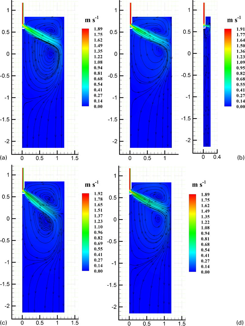
Velocity contours with streamlines at X–Y centre plane of a conventional, b four-spout, c diffuse type and d tunnel bottom nozzle (colour version available online)
The computed results show a good agreement with the water modelling results. As shown in Fig. 10b , with the four-spout nozzle, a portion of the jet flows directly to the wide wall, causing three circulation zones, which is presented in the Y–Z centre plane below 170, 350 and 1750 mm of the meniscus respectively. Therefore, in the X–Y centre plane, the flow impinges slightly higher than for the other cases. Figure 10c shows that the impinging point of the diffuse type nozzle is lower than the mould exit, even though it has the highest flow velocity in the nozzle. This phenomenon is the main reason to cause difficulty in inclusion removal and solidified shell formation.
Level profile
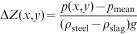
In order to compare with the level fluctuations measured in the experimental work, level movements were considered in the numerical simulation. Figure 11 shows the surface profiles computed from the surface pressure of the simulation. The level displacement (ΔZ) was computed from the equation29
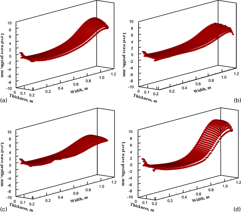
Level wave profiles of mould with a conventional, b four-spout, c diffuse type and d tunnel bottom nozzle
As indicated in Fig. 11, the data are approximately similar to the experimental results presented earlier. Across the entire top surface, the wave motion of the tunnel bottom nozzle is larger than in the convention case. With the maximum 8 mm fluctuation, the wave moment of the tunnel bottom nozzle is desired in the ultrathick condition. On the contrary, the level profiles are obviously flat in the four-spout and diffuse type cases. As a portion of liquid steel impinges at the wide wall, the surface moves higher near the quarter position in the case of the diffuse type nozzle.
Surface velocity
Figure 12 shows in both contours and data points the surface velocity along the wide face centreline for all four nozzles. Owing to the larger buffer cavity, the velocity magnitude in the ultrathick mould is relatively smaller than that in the conventional slab mould.

Comparison of surface velocity along wide face of centreline for four nozzles (colour version available online)
For the diffuse type nozzle, the downward jet is pulled greatly by the casting velocity, which leads to less upward flow and weak, while uniform, surface mobility. The four-spout nozzle has a similar surface velocity distribution but ∼20% difference at the quarter area compared with the conventional nozzle. The maximun velocity at the quarter position in the tunnel bottom nozzle gives great contruibution to refreshing the surface of liquid steel, especially the flow velocity at the narrow wall effectively avoids the formation of dead zone and freezing of the steel.
Temperature distribution
The temperature distribution at the mould surface is one of the most important considerations.31, 41, 42 Inappropriate temperature fails to provide the required heat for flux melting and heat transfer between the mould and the shell. Thus, a reasonable nozzle should improve the heat distribution at the surface, especially in ultrathick mould, which has a larger surface area to give out heat.
Figure 13 indicates the temperature distribution at the mould surface for the four different nozzles. The surface temperature field with the tunnel bottom nozzle is slightly higher than the others due to the heat brought by the fresh liquid steel from the nozzle and the low circulation zone. There is a smaller temperature gradient in the four-spout nozzle; nevertheless, the temperature of the impinging point at the wide face is as high as 1802 K. This has a detrimental effect on the uniform growth of solidified shell. The low temperature zone at the surface with diffuse type nozzle is quite larger than that of other three cases, but the corner area of the surface gives a higher temperature, which indicates, although this effect is fairly minor, the diffuse flow reaches this area.
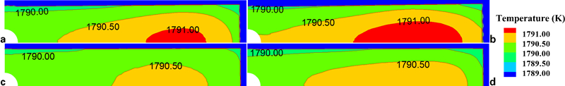
Contours of temperature at mould surfaces for four nozzles
The steel temperatures on the X–Y centre plane, 100 mm from the narrow wall, are compared in Fig. 14. In the upper circulation zone, the temperature distributions are similar except the diffuse type case because of the weaker impinging energy at the narrow wall. In the lower circulation zone, the temperature declines rapidly at the point of 1500 mm below the mould exit except for the tunnel bottom nozzle, in which vortices move closely to the narrow face, and liquid steel refreshes more continuously than the other three cases.
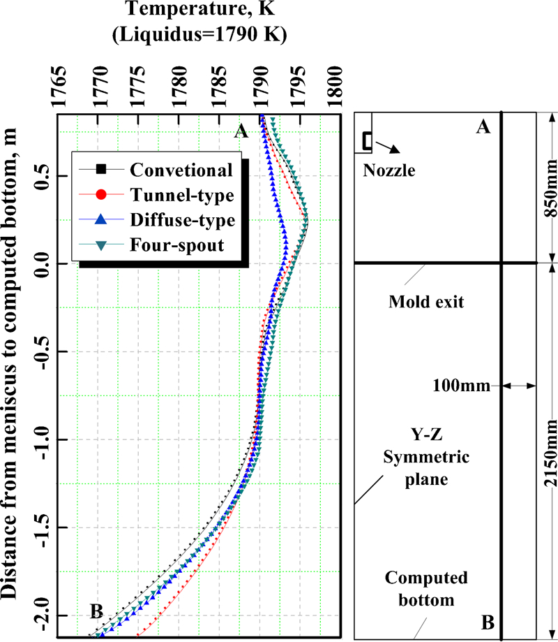
Comparison of temperatures at line in mould X–Y centre plane 100 mm from narrow face for four nozzles
Shell thickness distribution
As the residence time of liquid steel in the mould increases, the cooling water continuously removes the massive quantity of sensible heat and a portion of latent heat, thus leading to steel solidification. Researchers43, 44 investigated the formation of defects in the continuous casting process and found that liquid steel flow patterns within the mould may erode the solidified shell thickness, often resulting in shell thickness variation around the periphery of the mould. The shell thickness must be able to withstand thermal and mechanical stresses while exiting the mould and proceeding to the secondary cooling zone without longitudinal segmentation or even tearing leading the breakout.
Figure 15 presents the shell thickness at the mould exit plane of four nozzle cases. At the narrow wall, the shell thickness varies from ∼17 to 25 mm; the conventional nozzle produces the thinnest while the diffuse type nozzle is the thickest, which results from the smaller jet velocity caused by diffusion. At the wide wall, the shell thickness increases from ∼18 mm to the maximum 24·5 mm, except of the four-spout nozzle, because its ports in the thickness direction impair the growth of solidified shell. At the 1/4 position, the shell thickness of the diffuse type nozzle is <22 mm, caused by the flow impinged here at the wide wall.
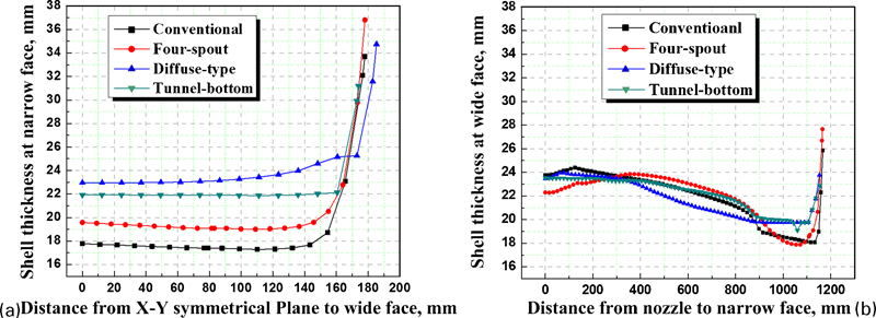
Comparison of shell thickness distribution in mould exit plane at a narrow face and b wide face for four nozzles
Field production
The optimal SEN has been applied in plant production, with the maximum section size cast to date being 420×1870 mm on a vertical with bending caster. The steel grade was medium carbon steel, and the casting velocity is 0·45–0·5 m min−1. The first casting slab showed that the slab shape and the surface quality were satisfactory; central segregation reached C0·5 to C0·1 grade (YB/T 4003-1997). Figure 16 shows photos of the production worksite and the slab.
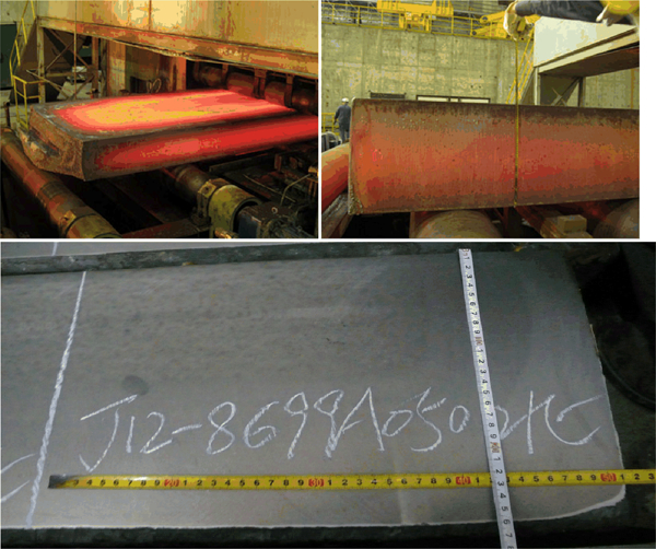
Photos of production worksite and slab
Conclusions
Based on physical and numerical simulations, the influences of four SENs on flow, temperature field and shell distribution within the mould have been investigated. The models predict the characteristics in a 420 mm thick slab mould and reveal new findings about nozzle structure in such an ultrathick mould, which are summarised as follows.
The water modelling and numerical simulation make it clear that the fluid flow phenomena in a 420 mm ultrathick mould are, by and large, similar with that of the conventional slab mould. However, the surface behaviour in the ultrathick mould was characterised by low velocity and small fluctuation.
At the nozzle port, the flow patterns are similar in the conventional and four-spout nozzles. The cross-section of the jet in the diffuse type nozzle is obviously wider than other three cases; therefore, this nozzle is more vulnerable to casting speed and gravity.
Velocity and temperature distributions with the conventional and four-spout nozzles are between the other two cases and are moderate in nature. The diffuse type nozzle causes the lowest surface velocity (maximum 0·07 ms−1) as well as the minimum temperature (1790·5 K) but still improves the flow behaviour at the meniscus to a certain extent.
In the diffuse type nozzle, physical and numerical simulations indicate that the slag entrainment is serious, especially at the nozzle area and the 1/4 position. Low velocity jet flow causes the thickest solidified shell (no less than 23 mm) of the mould exit at narrow face but leaves the minimum shell thickness at the wide face.
The tunnel bottom nozzle shows the maximum surface velocity and temperature, which indicates a lively surface behaviour and a favourable heat transfer between mould flux and surface flow. The shell thickness is uniform and thick enough at the mould exit to avoid breakout. Therefore, the tunnel bottom is the optimal SEN design, and the slab quality is satisfactory, and this has been proven by plant production.
Footnotes
Acknowledgements
The authors would like to express their thanks to the financial support from the Natural Science Foundation of China (NSFC) (grant no. 50774105).