
Abstract
In the production of tool steel, the control of secondary metallurgy plays an important role to meet the rapidly increasing demands for clean steel, as impurities and non-metallic inclusions can reduce its mechanical properties. This study focuses on the influence of stirring rate during the vacuum degassing of liquid steel on the inclusion characteristics. During this treatment, both gas and induction stirring are used; thus, fluid flow simulations were made for the vacuum treatment of melts at high (900 A+100 L min−1 Ar) and low (700 A+10 L min−1 Ar) stirring rates. By decreasing the Weber number to a value smaller than the critical value (Wecrit = 12·3) at a lower stirring rate, the probability for dispersion and entrapping of slag inclusions into the liquid steel significantly decreases. Five plant heats were carried out with different rates of induction stirring and argon flow in the ladle during vacuum treatment. The results gained by light optical microscopy investigation show that the total amount of large size single inclusions (>11·3 μm) in steel samples after vacuum treatment and in the final product decreases considerably with a lowered stirring rate. Thus, the experimental results support the theoretical results based on the Weber number.
Introduction
The demand for clean steel, i.e. steel with low amounts of impurities and non-metallic inclusions, is one of the largest challenges for steel producers. For instance, tool steels are often used under high stress; therefore, they are sensitive to defects acting as stress raisers, which in the worst case will give a drastic reduction in tool life. To prevent premature damage of the tool, it is essential to reduce the inclusion amount, size and types to non-harmful levels.
Non-metallic inclusions in steel originate from different sources, such as deoxidation products, reoxidation of steel, entrapping of slag droplets, etc. By the investigation of inclusions in AISI H13 tool steel,1 – 4 it was found that spherical inclusions >6 μm in steel after vacuum treatment had a similar composition as the top slag. Therefore, it was concluded that these slag inclusions (>6 μm) were entrapped and introduced to the steel by intensive stirring of the melt during vacuum treatment.
During the current vacuum degassing of this tool steel, an open eye zone (OEZ) is maintained during the whole treatment process (30 min) in order to ensure that the intensive gas stirring is working properly. A schematic illustration of slag–metal stirring close to the OEZ is shown in Fig. 1. The main purpose of an OEZ is to expose the liquid steel to the surrounding vacuum atmosphere to promote rapid removal of nitrogen, sulphur and hydrogen from the melt.5 Moreover, the intensive mixing of slag and metal promotes a more complete and faster desulphurisation due to a large reaction area. However, it may be proposed that this OEZ also is a major source of entrapped droplets from the slag into the melt. The slag can especially be dispersed near the OEZ due to the high gas stirring rate in this region. Thereafter, it can further be transported into the steel by the melt flow due to the flow field induced by induction stirring, as shown in Fig. 1. Previous results by Jonsson and Jönsson6 for a gas stirred ladle showed that the chance for slag entrapment into the steel increased at higher gas flow rates.
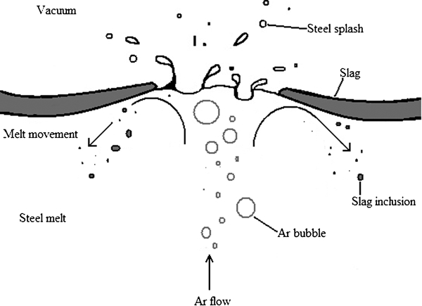
Schematic illustration of slag–metal movement close to open eye zone during vacuum degassing with argon stirring
The present study focused on the influence of stirring conditions during vacuum degassing on the content of harmful non-metallic inclusions in liquid steel and the final product of tool steel (AISI H13). The large size inclusions (>5 μm) were investigated by microscopy in steel samples taken from the ladle before and after vacuum degassing as well as from the final product. Moreover, the contents of nitrogen and sulphur in steel samples were determined.
Experimental
Five plant trials were performed at Uddeholm AB to investigate the effect of the stirring rate of the melt during vacuum treatment on the inclusion characteristics in the steel. These were performed during the vacuum degassing of tool steel (AISI H13) in a ladle under different stirring parameters. The composition of the steel is shown in Table 1.
Analysed steel composition/mass
At Uddeholms AB, the steel making process is a 65 t scrap based electric arc furnace. After tapping into a ladle, the steel is deslagged, and then a new synthetic slag is added, as well as deoxidiser and the remaining alloys. When the steel has the right temperature and chemical composition, the ladle is transferred to the vacuum degassing station. After ladle treatment, the steel is cast into ingots using an uphill casting technique.
The stirring of the melt in the ladle during vacuum treatment was carried out by a combination of induction stirring and argon gas stirring, the latter using two porous plugs positioned at the bottom of the ladle. During the trials, the vacuum treatment (30 min) was divided into two periods: period I (0–15 min) and period II (15–30 min). The main parameters of induction and gas stirring are given in Table 2. The stirring during period I was very intensive using an induction stirring of 900 A and a gradually increasing argon flowrate of up to 100–150 L min−1. In this case, two OEZs (liquid steel surface) on the slag surface in the ladle could be observed in the process camera. During this period of vacuum treatment, the contents of hydrogen, nitrogen and sulphur decreased rapidly. Moreover, they reached low enough levels to meet the steel grade demands. The complete vacuum treatment of reference trial (heat A) was carried out using the standard procedure using induction stirring with a 900 A current and an argon flowrate of 100 L min−1.
Experimental condition of industrial heats
*Induction stirring/Ar–gas flow.
The stirring of the melt during period II in heats B–E was lower than during period I, without an open eye zone on the slag surface. The induction stirring in this period was decreased from 900 to 800 A (heats B and C) and to 700 A (heats D and E). The argon flow rate during period II of these experimental heats was also decreased gradually from 100–150 up to 5–20 L min−1.
The inclusion characteristics and the nitrogen and sulphur contents in the steel were determined from lollipop samples with a 6 mm thickness. These were sampled automatically using argon protection before (BV) and after (AV) vacuum treatment for each experimental heat. Moreover, a piece of the solidified, heat treated and rolled steel was taken as a final product sample (FP).
The inclusion characteristics (number and size) were determined on cross-sections of the steel samples. The surface of each sample was ground (∼1 mm depth) and polished. Thereafter, the samples were observed in a light optical microscope with a magnification of ×200. In this study, the total observed surface area was ∼900 mm2 for samples BV and AV and ∼3000 mm2 for sample FP. Depending on the size and shape, all inclusions were classified into different types, as given in Table 3.7 The inclusions of type D represent single particles with spherical or irregular shapes. The inclusions of type B are single elongated inclusions or a band of smaller inclusions, which are spread out in the steel matrix in the rolling direction. Note that only D type inclusions were found in samples taken from liquid steel.
Number of inclusions in each heat
*Inclusions from samples taken after vacuum degassing.
The nitrogen and sulphur contents were determined at the Uddeholms AB laboratories by first grinding the samples and cutting 0·5 g pieces from the samples. Thereafter, the pieces were placed in a LECO instrument where the sample was combusted to determine the N and S levels.
Results and discussion
Evaluation of slag entrapping into liquid steel during stirring
Doostmohammadi3 investigated inclusions from the same steel grade and found that spherical inclusions >6 μm in steel after vacuum treatment had a similar composition as the top slag. It was concluded that these slag inclusions were entrapped and introduced to the steel by intensive stirring of the melt during vacuum treatment. The number and size of entrapped slag inclusions to the steel depend on the stirring rate.
Based on the modelling and simulation results,6,8 – 14 it was found that the slag droplets become dispersed and introduced into the steel melt if the flowrate is larger than a critical value. The Weber number was used for the evaluation of the possibility for the slag dispersed into the liquid steel. Based on previous results of modelling13, 14 and simulation,6 it has been shown that the probability of slag transfer into steel increased drastically when the Weber number reached a value ⩾12·3.
In this study, the Weber number was estimated for the steel–slag melt in the ladle at different stirring parameters: (1) for a 900 A induction stirring and a 100 L min−1 argon flow and (2) for a 700 A induction stirring and a 10 L min−1 argon flow. The Weber number, We, was calculated as follows6
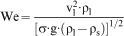
The Weber number was determined in the following two positions (Fig. 2): the a-layer runs along the steel and the slag/steel interface in the open eye zone, while the b-layer is between the steel and the slag interface just below the open eye.
Schematic illustration of movements of steel and slag melts at high stirring rates (900 A): figure also shows different layers (a and b) selected for estimation of Weber number
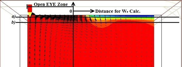
The results of the Weber number determinations during vacuum treatment of a melt at high (900 A+100 L min−1 Ar) and low (700 A+10 L min−1 Ar) stirring rates are shown in Figs. 3 and 4, respectively. The We values were calculated as a function of radial distance from the OEZ for a- and b-layers, as defined in Fig. 2. It can be seen in Fig. 3 that the Weber number for the b-layer is higher than that for the a-layer. However, in both cases, the Weber number near the OEZ is above the critical value (Wecrit = 12·3). The maximum values, Wemax, are 15·6 and 19·2 for the a- and b-layers respectively. Therefore, the slag can be dispersed into the liquid steel at the given high stirring rates. However, the Weber number decreases significantly at low stirring rates, as shown in Fig. 4. In this case, the Wemax values for the a- and b-layers reach 5·3 and 7·9 respectively. It is apparent that the Weber number at these stirring parameters is significantly smaller than the Wecrit value of 12·3. This decreases the chances of slag being dispersed from the slag into the steel melt.
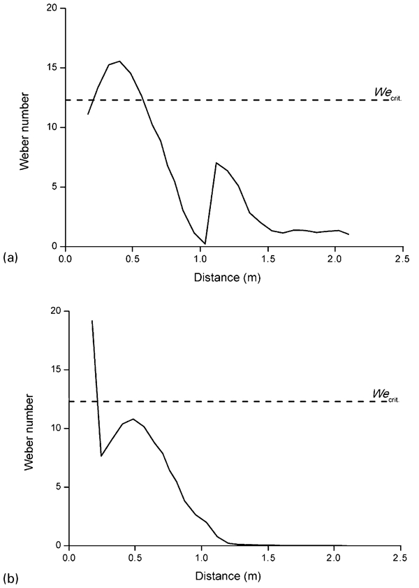
Weber number determined for a a-layer and b b-layer (defined in Fig. 2) by vacuum treatment of melt at high (900 A+100 L min−1 Ar) stirring rates
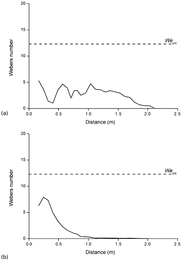
Weber number determined for a a-layer and b b-layer (defined in Fig. 2) by vacuum treatment of melt at low (700 A+10 L min−1 Ar) stirring rates
In this study, the calculated Weber number was used as a numerical parameter of stirring rate for the evaluation of the effect on the entrapping of slag droplets to the liquid steel.
Evaluation of inclusion characteristics in experimental heats
The number of inclusions per unit volume of steel after vacuum, N
V(AV), can be estimated using the following equation
Schematic illustrations of flotation and entrapping of slag droplets at high and low stirring rates are shown in the upper (a) and lower (b) diagrams of Fig. 5, respectively. It is apparent that the number of inclusions in steel after vacuum degassing depends on the initial number of inclusions in the steel before vacuum treatment as well the amount of removed inclusions by flotation [N V(Fl.)] and new inclusions introduced by dispersed inclusions [N V(Disp.)]. It is safe to assume that the number of large size slag inclusions, which are dispersed into the liquid steel at low stirring rates (Fig. 5b ), is significantly smaller in comparison to those at high stirring rates (Fig. 5a ). Therefore, it may be expected that the number of large size inclusions after vacuum treatment will decrease with a decreased stirring rate.
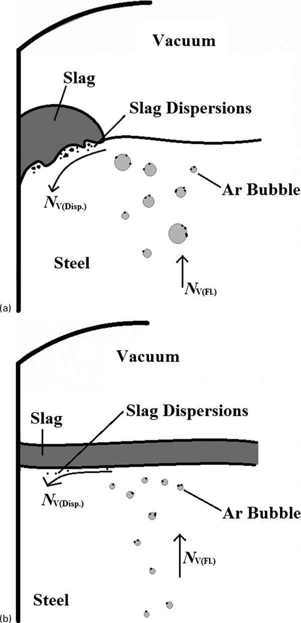
Schematic illustrations of flotation and entrapping of slag droplets at a high and b low stirring rates
Based on the results of previous studies,3,17 – 19 the time for vacuum treatment of steel in the ladle was divided into two periods with high (period I: 0–15 min) and low (period II: 15–30 min) stirring rates, as given in Table 2. The stirring of the melt during period II in heats B–E was gentler so that no open eye zone was formed. It should be pointed out that it is difficult to maintain a given constant argon flowrate (10 L min−1) in the ladle through two porous plugs under production conditions. This is due to partial clogging of the plugs. However, the argon flow during the major time in period II in heats B–E was varied in the range from 5 to 20 L min−1.
The effect of stirring rate on the inclusion characteristics was determined by a two-dimensional investigation of inclusions using light optical microscopy. The numbers of inclusions per unit area, N A, of steel samples taken before vacuum degassing and after vacuum degassing are shown in Fig. 6 for single inclusions of type D.7 It can be seen that the difference between the number of inclusions before and after vacuum degassing (ΔN A = |N A(BV) − N A(AV)|) increases significantly with a decreased stirring rate during period II. Thus, the ΔN A value for DH inclusions (11·3–22·4 μm) increases from 0·004 mm−2 in the reference heat A (900 A and 100 L min−1 gas) to 0·011–0·013 mm−2 for heats D and E (700 A and 10–20 L min−1 gas). The ΔN A value for DP inclusions (>22·4 μm) increases from 0·001 mm−2 in the reference heat A to 0·007 mm−2 for heat E. It should be pointed out that the number of DH and DP inclusions in liquid steel samples after vacuum treatment for all experimental heats with lower stirring rates is considerably smaller compared to those for the reference heat (heat A). Moreover, from Table 3, it can be seen that the amount of DH type inclusions reached the desired goal for all experimental heats, including the reference heat (heat A). Furthermore, the desired goal for DP inclusions was reached for heats B, C and E respectively. However, this goal was not reached for the reference heat (heat A) and heat D. This can be explained by the presence of an uneven argon flow through the porous plugs for these heats. As mentioned earlier, it is hard to fix a certain gas flow under production conditions due to, for example, partial clogging of the porous plugs.
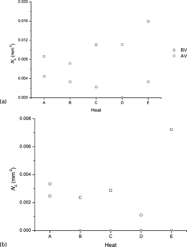
Number of inclusions on metal surface of samples before (BV) and after (AV) vacuum treatment for inclusion types a DH (11·3–22·4 μm) and b DP (>22·4 μm)
The fact that the set goals in Table 3 were reached can be explained by a drastic decrease of slag inclusions dispersed into the liquid steel at lower stirring rates (We < Wecrit) during the final period of vacuum treatment. According to the obtained results, it can be concluded that the lower stirring rate during period II contributes greatly to a decrease in the number of large size inclusions after vacuum treatment.
Figure 7a shows the amount of DH and DP inclusions present in the final product samples. The amount of these inclusions was in general higher than those found after vacuum degassing (Table 3 and Fig. 6). After vacuum degassing, the steel is slowly stirred and then cast into ingots. In these two steps, inclusions might be introduced from ladle refractory or from the ingot mould. The inclusions introduced from the refractory come from the wear of the refractory or from uneven parts of the refractory after refractory reparations. In additions, inclusions may be introduced during the uphill ingot casting process, specifically from wear of the runner refractory material or due to reoxidation from the mould flux during the initial turbulent filling of the steel into the mould. Therefore, it can be assumed that these inclusions were not generated from the vacuum degassing treatment, but rather from the final stirring, casting or from solidification and heat treatment of the tool steel. Furthermore, it can be observed in Fig. 7a that the modified heats (heats B, C, D and E) still have a lower amount of DH and DP inclusions in the final samples compared to the reference heat (heat A).
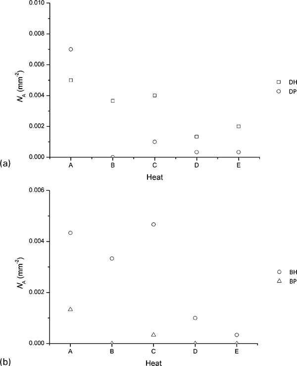
Number of a type D and b type B inclusions in steel samples of final product
The compositions of different inclusion types were determined in the steel samples taken after vacuum treatment (AV) and from the final product samples (FP) using an SEM equipped with EPMA. The typical morphology and compositions of observed DH, DP and BH, BP inclusions are given in Table 4. For the sake of comparison, the composition of the top slag during vacuum treatment is also given. It can be seen that the spherical DH and DP inclusions present have similar compositions as the top slag. However, the MgO and SiO2 contents in the spherical inclusions are slightly lower than those found in the top slag. This can be explained by a reduction of these oxides by Al in the steel. Normally, the concentration of Al in the steel melt is higher in the bulk than at the slag/steel interface. At the steel/slag interface, strong deoxidisers such as Al react with less stable oxides present in the top slag, as has been discussed by Andersson et al. 20
Main characteristics of observed inclusions in steel samples
*S content in slag.
Overall, these results indicate that the spherical DH and DP inclusions derive from the top slag, and that they most likely have been dispersed from the slag to the steel due to intense stirring during vacuum treatment. Some variation of composition can be explained by the reaction of entrapped slag inclusions with the surrounding metal melt, as discussed above. The irregular DH and DP inclusions mostly consist of Al2O3–MgO containing some MnS. Although these inclusions are not correlated with the ladle slag, the stirring rate of the melt in the ladle can also significantly influence the separation of these inclusions from the melt.
The numbers of B type inclusions (single elongated inclusions or a band of spread out smaller inclusions) in the final product after rolling are given in Table 3 and shown in Fig. 7b . It can be seen that the N A values for BH (11·3–22·4 μm) and BP (>22·4 μm) type inclusions in most experimental heats are smaller than those in the reference heat (heat A). In addition, the data in Table 3 show that the target for BH type inclusions in the final product samples was not reached for any of the experimental heats. However, the target for BP type inclusions was reached for heats B, D and E respectively. Typical photographs and compositions of elongated BH and BP type inclusions are given in Table 4. It can be seen that these kinds of inclusions consist of different parts with various compositions, such as Al2O3–MgO oxides and MnS sulphides. In addition, the content of CaO and SiO2 is very low (0–5%). It is apparent that the elongated BH and BP inclusions are not slag inclusions, which were dispersed into the liquid steel at high stirring rates. However, although the B type inclusions are not slag inclusions, the number of elongated BH and BP inclusions in the final product tends to decrease with a decreased stirring rate during vacuum treatment, as shown in Fig. 7. This is most likely due to separation of these inclusions to the top slag during intense stirring.
Removal of nitrogen and sulphur
In addition to targets for different inclusion types, steel grades typically also have limits on the sulphur and nitrogen contents. For the steel grades studied, the limits are ([%N]max<0·012 wt-% and [%S]max<0·0015 wt-%). Therefore, both the nitrogen and the sulphur contents were analysed in the samples taken before and after vacuum treatment to be sure that the desired levels were reached. Figure 8 shows the results obtained in a previous study8 as well as in the present study. It can be seen that the contents of nitrogen and sulphur in the melt after vacuum treatment of the reference heat (A) and experimental heats (B, C, D and E) are significantly lower compared to the given limit for the investigated steel grade. Thus, the changed stirring practice tested in this study did not have a negative influence on the N and S contents in the steel.
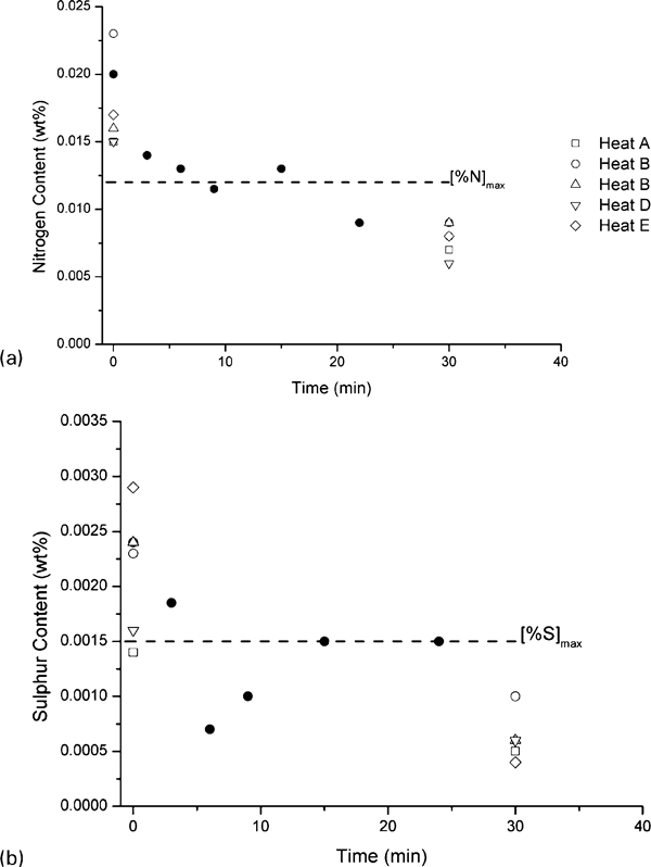
Content of a nitrogen and b sulphur in tool steel during vacuum treatment
Conclusions
The effect of different stirring conditions during vacuum degassing in the ladle on the inclusion characteristics was investigated based on five plant trials using an AISI H13 tool steel. During the trials, the vacuum treatment (30 min) was divided into two periods: period I (0–15 min) and period II (15–30 min). The stirring of liquid steel and slag during period I was very intensive using an induction stirring of 900 A and a gradually increasing argon flowrate of up to 100–150 L min−1. However, during the second vacuum treatment period, the induction stirring was carried out using the following three currents: 900, 800 and 700 A. Steel samples were taken before and after vacuum degassing and from the final product. The inclusion size distribution was determined using optical light microscopy and the inclusion composition using SEM in combination with EPMA. The following specific conclusions can be made based on the results from this study.
The calculated maximum value of the Weber number, Wemax, decreases drastically from 15–19 at high stirring rates (900 A+100 L min−1 Ar) to 5–8 at low stirring rates (700 A+10 L min−1 Ar) of the melt during vacuum treatment. By decreasing the Weber number to a value smaller than a critical value (Wecrit = 12·3), the number of slag inclusions dispersed and entrapped into the liquid steel should theoretically significantly decrease.
By decreasing the stirring rate of the melt during the final 15 min of vacuum degassing, the number of large size single inclusions (type D, >11·3 μm) in steel samples after vacuum treatment and in the final product after rolling decreases considerably in comparison to those from the current steel making praxis.
The spherical D type inclusions investigated in samples taken after vacuum treatment and in the final product samples show similar compositions as for the top slag. Therefore, it can be concluded that these are actually dispersed into the steel during intense stirring.
The number of elongated BH (11·3–22·4 μm) and BP (>22·4 μm) inclusions, in the final product after rolling, tends to decrease with a decreased stirring rate during vacuum treatment.
The content of nitrogen and sulphur in the melt after vacuum treatment of reference heat (A) and experimental heats (B, C, D and E) with lower stirring rates during the final 15 min of vacuum degassing is significantly smaller compared to the given limits for the investigated steel grade.
Footnotes
Acknowledgements
The authors wish to thank VINNOVA and Jernkontoret for the financial support to this study, the operators at Uddeholm AB for their assistance during the plant trials and Dr J. Alexis of MEFOS for performing the CFD calculations, in which the results were used in the calculations of the Weber numbers.