
Abstract
Refractory wear and skull growth on the hearth walls and the bottom of the blast furnace have been researched. A series of thermocouples were installed in the hearth, and the temperature measurements were recorded in a structured query language every minute. A heat transfer model was used to study the temperature evolution and hearth wear profile using a commercial software package (MATLAB version 5.0) based on computational fluid dynamics. The location of the 1150°C isotherm in the hearth lining has been calculated. An online monitoring tool was used to analyse the temperature distribution in the hearth and offers, to the plant operators, periodic information on the refractory state. Electromotive force (EMF) probes were installed in the hearth to estimate the variations in the liquid level in the hearth and to determine the thermal state (TS) evolution. Good correlation is seen between EMF and TS, and the EMF amplitudes in the different tapholes follow and even precede the local TS.
Introduction
Much research has focused on blast furnace hearth, for instance, analysing refractory damage in order to help furnace operators take protective measures in the identified hearth wear area to improve furnace safety and prolong its service life.1 – 5 Damage in the hearth area is difficult to repair, and it is therefore vital to monitor the hearth refractory condition so that its failure can be prevented and operating practices can be adjusted to maximise hearth life.
The hearth is monitored by an array of thermocouples to estimate the location of the 1150°C isotherm; the location of this isotherm can be used to indicate if the refractory is severely eroded or if there is a lot of skull on the hearth walls. There are a number of modelling techniques for determining the location of the 1150°C isotherm: (i) two-dimensional modelling,6 (ii) two-dimensional heat transfer modelling7, 8 and (iii) two-dimensional heat transfer, fluid flow, mass transfer modelling.9, 10 A severely eroded lining may indicate that a relining should be scheduled to avoid breakout. To be able to take the correct measures against erosion or against the opposite situation that is a skulled hearth, it is important to know the thermal state (TS) of the hearth.11
In the present work, an online monitoring tool was used to analyse the temperature distribution in the hearth. Measurements from 200 thermocouples were recorded in a structured query language database every minute. This tool offers periodic information on the refractory state to the plant operator. A heat transfer model based on the thermocouple readings in the refractory can be used to consider the present state of the hearth, i.e. if it is severely eroded or if there are considerable amounts of skull. Electromotive force (EMF) probes have been installed in the blast furnace and are used by operators as an indicator of hot metal temperature and to estimate variations in the liquid level in the hearth. The EMF signals were analysed to determine the hearth TS evolution and to find any possible correlation that could improve the information available. Different temperature profiles have been calculated, including 1150°C. The position of the 1150°C isotherm inside the hearth throughout the furnace campaign will be a manifestation of the level of wear that hearth presents in different areas.
The results of the present research carried out should be useful to increase the stability, security and campaign life of the blast furnace.
Heat transfer model
This model was used to study the temperature evolution and the hearth wear profile. It analyses the thermal conditions of cooling at the hearth bottom and evaluates three types of refractory design: refractory bricks, carbon blocks and mixed design. The temperature distribution calculation is based on the location of the 1150°C isotherm in the hearth lining, which provides the best fit between the temperature distribution calculated by the model and that measured by thermocouples inside the lining.
Usually, depending on the refractory design and composition, hearth models may be grouped into three types:
traditional refractory design constructed preferentially with a silicon–alumina refractory material. Until the 1960s, hearths were built mainly in this way, and the furnace (hearth) campaign life rarely exceeded 2 years
thermal design (from the mid 1960s) in which a carbonaceous anthracite, anthracite–graphite or graphite material is only used. Simultaneously cooling of hearth walls and bottom technologies (water or air) began. These technologies increased significantly the campaigns to around 7 years; however, heat losses were greater, impacting negatively on the consumption of coke
ceramic cup design in which oxide or nitride ceramics are in contact with the hot metal and anthracite–graphite is in contact with the hearth walls and bottom. This design was proposed at the end of the last century and consisted of oxidic/nitrided (oxides and nitrides of aluminium) in contact with hot metal, with carbonaceous (anthracite with greater or lesser proportion of graphite) in contact with the furnace walls (steel plate construction). With this solution, the campaign life is extended to >15 years and with heat losses lower than with the thermal solution.
The present work takes into account research carried out on the mathematical simulation of hot metal flow and heat transfer in the hearth. This research is based on the free space formation in the hearth using a cold two-dimensional model,12 the erosion analysis by numerical computation13 and a model to simulate the effect of a coke free gutter full of low porosity material on the temperature distribution and rate of tapping.14, 15
A heat transfer model has been designed using an axisymmetric finite element method to calculate the temperature profile inside the hearth refractory in order to estimate the maximum wear. Using a commercial software package, PDE toolbox of MATLAB (version 5·0), CSIC/CENIM has developed a model based on computational fluid dynamics. The effect of the hot metal temperature and cooling conditions has been researched using a moving boundary approach at the hot metal/refractory interface, in which, depending on the temperature distribution, the hot metal thermal properties sequentially replace the refractory thermal properties.
The basis of the mathematical formulation is the balance between mass and heat conservation. The following suppositions may be established. (i) The deadman is floating. (ii) Heat is not generated in the refractory, and therefore, this thermal source may be disregarded. (iii) The problem may be simplified to two dimensions as there will be small irregularities in the geometry, material properties and limit conditions in the angular direction, and so angular thermal conductivity may also be disregarded. (iv) A steady state is considered, because changes on the hot side and limit conditions on the cold side are slow, and so the temperature distribution in the hearth is almost static.
Using the variational principle and making a finite element discretisation, the heat balance equations can be reduced to the following form
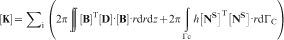
In this work, a standard two-dimensional four-noded isoparametric quadrilateral element has been used. Since the thermal conductivity values and consequently the heat conduction matrix [
In order to evaluate the model, some data and input properties, in conjunction with the temperatures measured in the thermocouples placed in the hearth lining, were necessary as follows:
hearth: internal and external diameter and height
molten liquid iron: production rate, average temperature, density, laminar viscosity, thermal conductivity, calorific capacity, thermal volumetric expansion coefficient, molten liquid iron thickness (from hearth bottom), liquid height above top of taphole and carbon diffusion coefficient for a melt (cast iron) with a certain % C
slag: height
hearth lining: thermal conductivity, calorific capacity and density
coke bed: particle diameter and density
other data: hearth wall and bottom cooling water temperature, conduction heat transfer coefficient in hearth side wall and bottom (as a function of the temperature measured by thermocouples) and convection heat transfer coefficient of cooling water.
To evaluate this model, the temperature profile and maximum hearth wear have been calculated using the ArcelorMittal blast furnace B design, as mentioned above (see Table 1). Furthermore, different hearth refractory materials could be studied including their thermal conductivity values as a temperature function for each material.
ArcelorMittal blast furnace B (BF-B) characteristics
Online supervision of hearth refractory state using advisory tool
For a long blast furnace (BF) lifetime, it is important to form a protective skull on the hearth side walls and bottom surfaces by means of an appropriate cooling system for these zones in order to avoid their overheating. An online monitoring tool is used to analyse the temperature distribution in the hearth and, consequently, the heat transfer between the lining materials and cooling system in order to establish the state of the refractory.
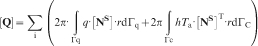
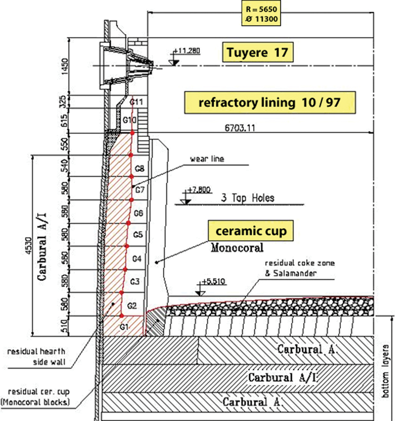
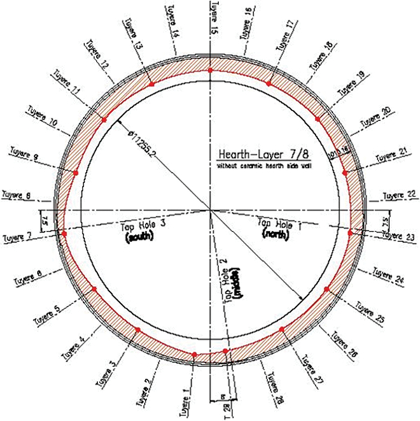
BF-B has >200 thermocouples fitted inside its refractory. Measurements from all the thermocouples are recorded in a structured query language database every minute. In parallel, the most significant process data are also recorded in the other sets of the same database. Figure 1 shows a cross-section of the thermocouple distribution. There are three horizontal layers in the hearth bottom and two vertical layers in the hearth wall at different levels. Figure 2 shows the current situation and the various thermocouple installed levels. The database also has information on the water temperature and cooling system temperatures, and so it is possible to monitor the evolution of thermal losses.
Thermocouples in BF-B hearth
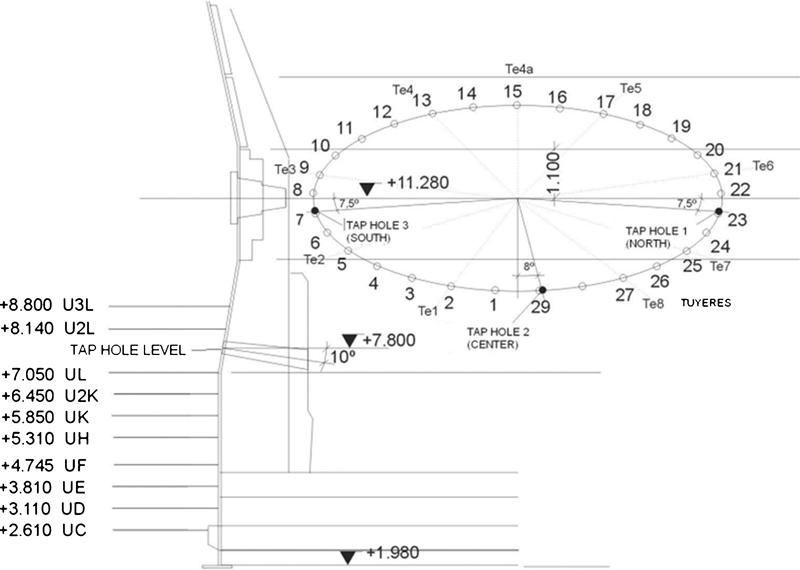
Thermocouple distribution along side walls and bottom of ArcelorMittal BF-B (TH1 = north, TH2 = centre, TH3 = south taphole)
The advisory tool offers to the plant operator periodic information on the refractory state using a thermocouple temperature graphic display in different positions and levels of the lining and calculating their evolution compared to the initial temperature values measured after the BF-B revamping period (start of 2003). The initial temperature data were selected by analysing the measured relationships between thermocouples from the present campaign start (end of January 2003).
With these online displays, it is possible to analyse when and where scaling appears and the progress of refractory wear on the hearth walls and bottom. An algorithm calculates the refractory thickness by comparing the selected data values with the values from the same thermocouples at the start date, according to the heat transfer model used.
Figures 3 and 4 show the evolution of temperatures comparing the initial data values (February 26, 2003), midterm values (May 11, 2006) and 4 year values (December 29, 2006). Figure 3a shows the temperature variations at level 2L, over the taphole, indicating that the temperatures basically decrease close to the taphole zone, probably due to the scaffolds produced during tapping. Figure 3b shows the temperature variations at level L, below the taphole, indicating that the temperatures rise close to the taphole area, due to the turbulence produced during tapping, with the consequent occurrence of refractory wear in this zone. Figure 4 shows the circumferential distribution of hearth temperatures at levels 2K and K, below the taphole levels. The temperature behaviour here is similar to that of level L.
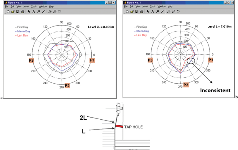
a hearth temperature variations at level 2L; b hearth temperature variations at level L (midterm values at 330° inconsistent due to problems with thermocouples)
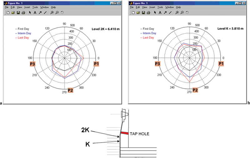
a hearth temperature variations at level 2K; b hearth temperature variations at level K
During the temperature measurements, abnormal thermal evolution has been detected in the readings from thermocouples close to the hot wall of the pad. Many of the thermocouples in the layers closest to the hot side, especially those near the centre of the hearth, showed erratic behaviour over time, with very low temperatures compared to the readings given by thermocouples closer to the cold side. This behaviour can be seen in Fig. 5, where the ‘red’ thermocouple is closer to the hot side. From the thermocouple inspection, it is deduced that the most likely reason for this mismatch is the presence of moisture inside the thermocouple casing: the protective corrosion cover allows cooling water to wet the internal insulation by porosity and diffusion. This problem leads to the dismissal of all pad temperature readings from the affected thermocouples and underlines the interest of using parallel monitoring systems in future hearth design, such as heat flux metres, which also allow the abnormal measurement detection and the estimation of thermal conductivities.
Abnormal behaviour of pad thermocouples. Dashed line thermocouple is closer to hot face and continuous line to cold face. The period of time is 10 months
Analysis of wear profiles
The revamping of blast furnace A (BF-A), at the end of 2004 (the end of its campaign life was in October 1997), allowed hearth wear profile analysis at the end of the campaign. The main aspects on the lining profile wear were as follows:
the ceramic wall had disappeared above the bottom block level
on most of the wall surfaces, including areas close to the taphole, the remaining carbon coating can be described as follows, starting from the hot side:
thick layer (∼500 mm) of damaged carbon blocks, heavily infiltrated with metal (Fig. 6)
thick brittle layer, often so damaged that it turns to dust
after an even more brittle transitory material (thickness, 20–50 mm), an undamaged carbon layer of thickness varying between 120 and 500 mm
finally, the rammed layer against the shell, whose appearance is normal.
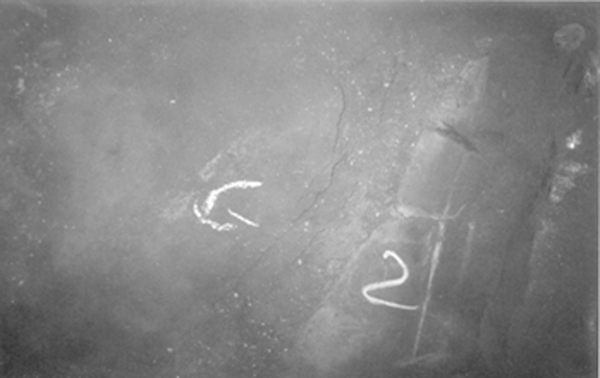
Aspect of brittle layer at level of G2, close to taphole no. 2 (brittle layer is located between ‘G’ and ‘2’)
The severest wear was located at the G2/G3 interface, i.e. at the level of the upper face of the upper ceramic bottom layer (Fig. 7). This is a normal position for the elephant foot. The lining located over the tapholes was also an area that suffered strong erosion (Figs. 8 and 9). The increase in wear here originated by the faster flow of metal and slag above the taphole area. As a consequence, the skull protection is less efficient. The brittle layer closest to the shell can be divided into three parts: on the sound carbon side, a very damaged layer of 50 mm thickness converted into dust, followed by plates of infiltrated material with a high iron content (100 mm thickness) and finally a second layer of 50 mm thickness also converted into dust. After this comes the thickest part (500 mm) considered as the damaged hot side of the carbon blocks, with some remaining adhered skulls.
Wear profile (elephant’s foot)
Wear profile above tapholes
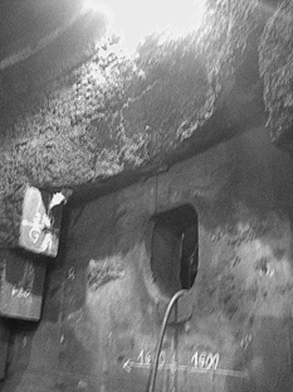
Above taphole no. 1 (north). The erosion of the carbon blocks is greater
The carbon block samples have been obtained by core drilling through the entire lining below taphole nos. 1 and no. 2 at the level of the elephant foot area in the hearth bottom (Fig. 10). Factors that can accelerate wear include a lack of protective skulls, which are washed out when the metal flow is fast (high productivity), the carbon conductivity is low and the hot metal infiltration is strong. As the lining hot side reaches the highest temperatures in this area, it is recommended to use carbon blocks with a constant linear change, maintaining low values established to limit stresses on the hot side of the lining. Alkali infiltration seems to cause more disintegration than zinc infiltration. The highest alkali contents have been found in samples converted into dust. It has also been observed in drilled nucleus samples that outside the brittle layer area, liquid hot metal infiltration is more intense than alkali and zinc penetration, which was not expected.
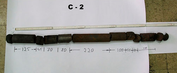
Core C2 sampled by drilling at level +5500 below taphole no. 2. From the left to the right: 50 mm rammed mass, 125 mm of unaffected material, 45 mm close to the brittle layer and with carbon dust, 70+80 mm of strongly metal infiltrated carbon and 220 mm of transition to the slag/lime/metal skull, then only skull
Thermal state and thermal profile analysis
Heavy wear was observed in the taphole area during the revamping of BF-A, to an extent of 1 or 2 m in width, produced by the faster hot liquid flow. Greater attention must be paid to this area in future designs as the current protection is not sufficient to assure good resistance against erosion. The results provided by the software developed by CSIC/CENIM to estimate the evolution of wear have been compared by ArcelorMittal with the aforementioned observations. Although the calculations were performed with a data set from BF-B, both furnaces have the same design and similar campaigns. According to CSIC/CENIM, higher temperatures are detected close to and below the tapholes than in other sections of the hearth, which indicates higher wear in these areas. This seems to be in accordance with the wear found during revamping. Moreover, the model points to higher temperatures in the elephant foot area, which is consistent with the observations.
On the other hand, the high wear found above the tapholes is not clear from the model results, which must be due to the presence of scaffolds or the lack of measurements from thermocouples sufficiently close to the wear zone. Successive statistical and correlation analyses have been carried out with the information provided by the thermocouples from the hearth and different furnace operating parameters, taking into account factors such as distribution of the nozzle pipe openings, horizontal and vertical thermocouple levels and the active taphole.
Thermal state and EMF
In a qualitative approach to determine the hearth TS, the data generally analysed by the operator are the hot metal temperature and the silicon content.16 Following this criterion, it is possible to define work areas for BF operation according to the hearth state (cold, hot or good) and to check this tendency, taking actions to correct any abnormal behaviour. As the temperature and the silicon percentage are intensive variables, the (%Si–T) couple defines a hearth energy function known as the TS
The area definitions are shown in Fig. 11. Level 0 is defined as the objective and corresponds to the target temperature and silicon resulting from the correlation.
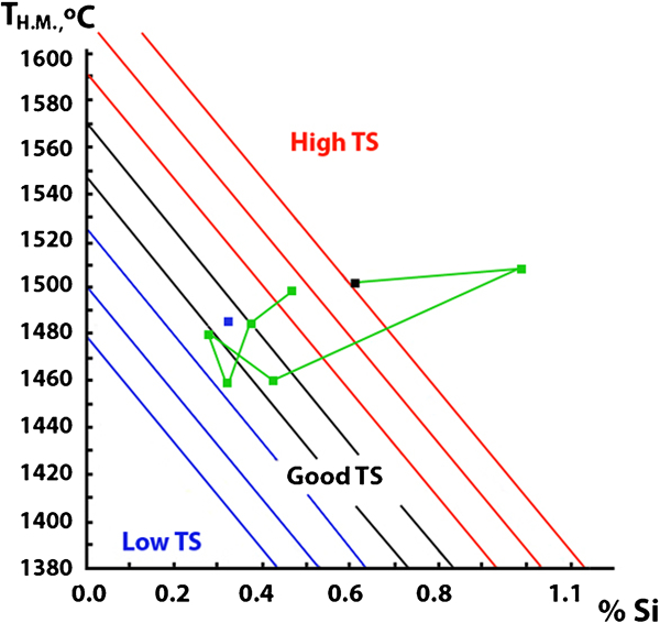
Thermal status graph
Electromotive force probes have been installed in BF-B to estimate variations in the liquid level of the hearth, and a strong correlation between the EMF measures and the iron level has been observed.17 The measurement of the EMF between two sensors that are welded to the furnace shell at two levels (one used as a common voltage reference) is a method to determine the amount of liquid in the hearth. The voltage value depends on the relation between slag and hot metal. It has been detected that the EMF signal shows a good correlation with the casting sequence; generally, the signal has a minimum at the end of casting.
The signals were analysed to determine the hearth thermal evolution and to find any possible correlation that could improve the information available. When different tapping sequences are observed, the general short term evolution of the EMF signals is seen to be directly related with the tapping sequence and the liquid level in the hearth, and is also especially well correlated with the TS, so that the highest EMF amplitudes mean higher TS values. This could be explained if the mechanism that produces EMF was better known. Recent studies18 indicate that chemical reactions at the interface between the hot metal and slag are responsible for the difference in voltage. Thus, a higher TS may mean higher reactivity with an increase in EMF amplitudes. The conclusion obtained from this simple analysis is that the tendency of the hearth TS is also reflected in the evolution of EMF. Figure 12 shows the correlation between the north probe average EMF of different melts and the TS. The direct relationship is clear.
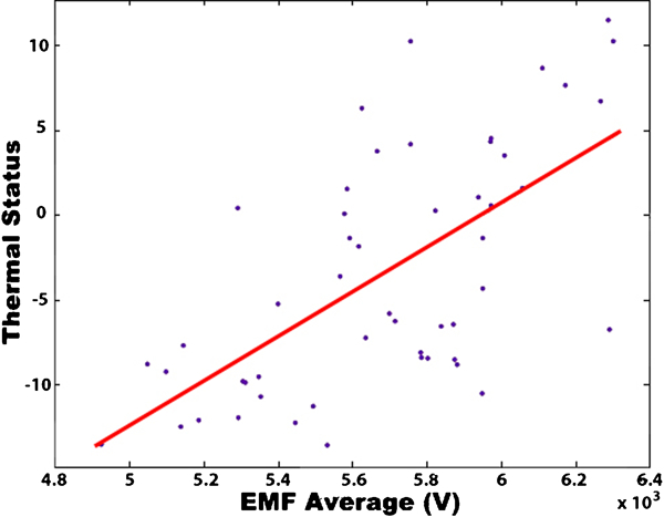
Correlation north probe EMF versus thermal status
The following analyses yielded new results. The local evolution of each of the measured EMF amplitudes has been verified, comparing their evolution with the hot metal temperature obtained during tapping in the corresponding taphole where the probe was installed. It has been seen that the relative difference in the EMF values measured by the probes placed in different tapholes is closely related with the difference in the hot metal temperature measured in those tapholes.
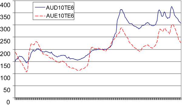
Figure 13 shows a sequence of melts, where the EMF amplitudes measured in the north and south tapholes have crossing points: when the EMF values of the north taphole are higher than in the south taphole, the measured temperatures are also higher, and the gap between the tapholes is high. When the reverse occurs, the gap decreases. In the end, the EMF values in the north probe are once again higher, and the gap tends to increase. This type of evolution is always similar; qualitatively, it can be said that the EMF amplitudes not only provide information about the filling level of the hearth and the overall TS but also seem to indicate the local TS in the different sectors of the BF where they have been installed.
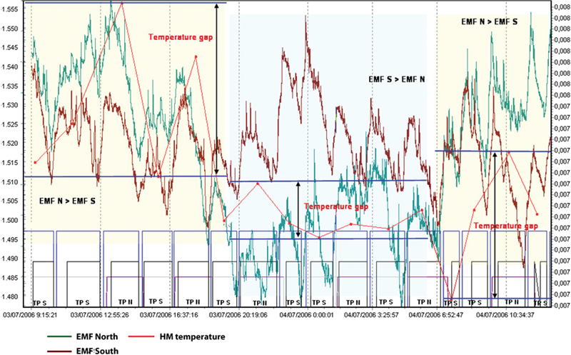
Typical EMF evolution during different taps. Hot metal temperature gap behaviour when the EMF values in different sectors of the hearth cross.
Thermal profiles
The information provided by the EMF measurement is used by the BF-A and BF-B operators as an indicator of the hot metal temperature and the TS evolution. In fact, the operators’ experience with EMF signals is that the amplitude not only follows but actually precedes the thermal conditions of the next tap. The operators habitually use this information as another tool to improve tapping practice. A study has also been carried out in relation with deviations that occur in thermocouples located at the same height and radial position but at different angular positions.19 For this purpose, erosion profiles have been calculated for selected angular positions by defining the cold side temperature limit conditions and using the data provided by the pairs of thermocouples located in these positions (Fig. 14).
Hot metal temperature effect at refractory interface on 1150°C isotherm position using EMF
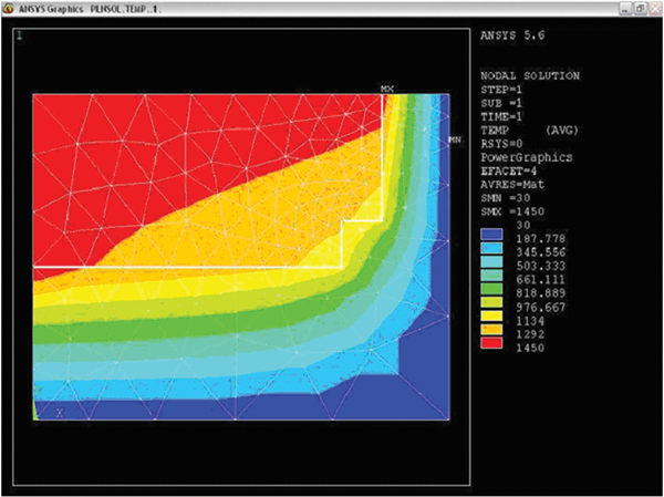
The limits of some conditions have been defined in the mathematical model to obtain the expected results. The first thing was to study heat transfer in the hearth refractory of BF-A. The metal/refractory interfaces in the side walls and bottom block have been fixed at the constant hot metal temperature of 1450°C. Convective limit conditions have been specified for the surface of the outer walls and the bottom block using average temperature data recorded in the plant, and approximate convective heat transfer coefficients have been taken for the cooling water and air. Furthermore, the surface of the refractory at the top and in the centre of the hearth has been considered to be adiabatic. After this, different temperature profiles have been calculated, including 1150°C, using different water and air temperatures. Convective coefficients have also been used to determine how cooling conditions affect the temperature profiles (Table 2). It has been seen that changes in the 1150°C isotherm for cold side limit conditions are negligible. However, when the 1150°C isotherm is calculated for different hot metal temperatures (e.g. 1400 and 1500°C), significant effects have been seen on the hot metal/refractory interfaces (Fig. 15). The behaviour of the 1150°C isotherm is studied by changing the temperature of the hot metal/refractory interface and its effect on refractory wear.
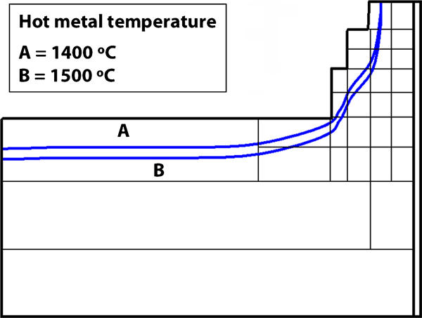
Effect of hot metal temperature at refractory interface on 1150°C position in BF-B hearth
Cooling conditions
Conclusions
On the basis of the results obtained about the wear mechanism of blast furnace hearth, the following conclusions may be drawn.
For the carbon blocks in the hearth under ceramic cup model/design to avoid the elephant foot profile, the following is recommended: higher block thermal conductivity but with good resistance to corrosion by hot metal, a low permanent linear change (of the refractory material as a consequence of the work of this material at high temperature) and a high level of microporosity.
Resistance to attack by alkalis and zinc is an important parameter for carbon quality. In its evaluation, the phenomena of both cracking and expansion must be taken into account. Blast furnace operators are interested in limiting the alkali and zinc content in the burden materials.
Differences in the TS at each taphole are indicative of asymmetric hearth conditions, which, in terms of long term evolution, may lead to differences in wear.
There is a direct correlation between the hearth TS and the evolution of EMF in the taphole area.
The information reported in the present work on the analysis of hearth refractory state has improved the understanding of the wear mechanism and will be useful to the operators of blast furnaces to allow future improvements in hearth design.