
Abstract
The article is devoted to the investigation of interaction between electrovortex and heat flows of liquid metal in dc arc furnaces with a bottom electrode. A mathematical model of liquid steel flows in a dc arc furnace with a bottom electrode was developed, and an algorithm of a three-stage solution was produced based on standard software packages. The results of electromagnetic, heat transfer and hydrodynamic analysis in industrial dc arc furnaces are given. It is shown that the Lorentz force makes up ∼30% of the volumetric gravity force and makes the main contribution to vortex flow of liquid metal in a dc arc furnace. The convection flows with the maximum heat power of furnace make a significant contribution to the vortex flow of liquid metal, and the maximum value of the vortex flow velocity is ∼1·5 times more than the movement without convection. The verification of results has been carried out by comparing them with general electrovortex flows theory, experimental data and results of similar software packages.
Introduction
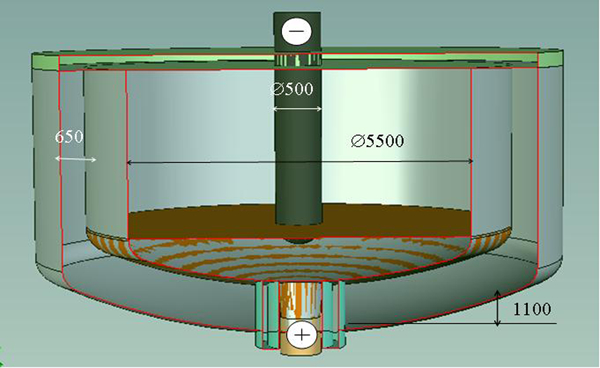
Direct current arc furnaces with a bottom electrode have become more popular in recent years, as such furnaces are more profitable and environmentally friendly than ac arc furnaces. 1–5 A typical example by Danieli Corporation is given in Fig. 1. 4 The principle elements of the furnace are as follows: a smelting bath and top and bottom electrodes. Its main parameters are as follows: furnace capacity, 100 t; diameter, 5500 mm; depth of bath with melted steel, 1100 mm; dc load, 80–100 kA; mainline voltage, 500–1000 V; power of current consumption, 40–100 MW; polarity, ‘+’ on bottom electrode; electrode diameter, 500 mm; lining thickness, 650 mm.
Industrial dc arc furnace with bottom electrode
Furnace operation has shown increased refractory wear at the bottom electrode, 5 the reason suggested being vortex flows of liquid metal caused by the Lorentz force. Vortex flows occur because of spatial inhomogeneity of the current density and electromagnetic field. However, mixing of liquid metal in the bath during smelting is necessary for homogenisation of alloys and temperature; therefore, the most important objectives are to estimate the Lorentz force intensity, the effect of different factors on the Lorentz force and the vortex flow character of the molten metal.
Smelting in electric furnaces is an extremely complex, energy consuming and expensive high temperature process, which is accompanied by powerful electric and magnetic fields and intensive liquid metal vortex movements. These conditions make experimental research much more complicated and explain why numerical modelling is the only reliable method of numerical estimation of such processes. One of the most important parts of the numerical modelling is to build an adequate model that takes into account specific characteristics of dc arc furnaces so that the processes can be better optimised.
The present paper describes the physical system, a mathematical statement and the physical processes in a dc arc furnace. During the liquid period, the impact of different factors is estimated with the help of the similarity criterion. The algorithm of numerical modelling of proceeding processes by standard software packages was developed. The numerical modelling for the working period of dc arc furnace of the cylindrical shape and of the given construction was carried out. As a result, the electromagnetic, heat and hydrodynamic fields were obtained, which allowed us to estimate the influence of Lorentz force and convection on the character of liquid metal vortex movement.
Physical processes in dc arc furnaces with bottom electrode
The operation period in a dc electric arc furnace can be divided into heating, refining of liquid steel and tapping. The time with liquid steel present ranges from 15 to 60% of the total operation period depending on the steel type and the quality of starting raw material. 1–4
In this type of dc arc furnace, the vortex flow of liquid metal is the result of spatial unevenness of the current with the absence of an outer magnetic field. The current in the liquid creates a magnetic field, which causes vortex movement of the liquid.
Convection flows make their own contribution to the vortex flow and appear as an uneven distribution of the temperature through the liquid volume. It is shown in the work 6 that heat convection in electrovortex flow (EVF) with axial symmetry appears when the radial gradient exists (∂T/∂r≠0). The direction of convection depends on the value of temperature gradient at the distance from axial symmetry.
To build a mathematical model of the processes in an electric arc furnace, the following assumptions can be made:
the medium is considered non-magnetic (the Curie point for steel is 760°C)
the medium is a good conductor and its permittivity can be neglected
the processes are steady
convective current, caused by the medium movements compared to the current of conductance, can be neglected
physical characteristics of the medium (conductivity, viscosity, heat–conduction indices, etc.) are assumed to be homogeneous and isotropic and depend on temperature
medium heating caused by viscosity (viscous dissipation of energy) can be ignored as compared to the Joule heating
chemical reactions are not taken into account.
During the liquid period, the temperature difference throughout the metal volume can vary depending on the mode of furnace operation. Thus, when the arc works at full power, the temperature ranges from 3500°C in the arc area at the cathode to 1650°C in the bottom electrode area and along the refractory surface. At low power, the temperature difference throughout the metal volume does not typically exceed 50°C.
The typical velocity of the liquid from the electromagnetic force can be estimated as u
0 = j
0
L(μ
0/ρ)1/2≈0·3 m s−1.
6
The Grashof number that defines the ratio of relative intensity of convection depending on the temperature range and EVF in the furnace is ranged in different periods from Gr = 0·5<1 (with the low power of the arc) to 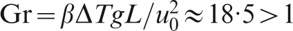
The relative power of Joule heating as compared with heat from the arc is low and makes up 
The magnetic Reynolds number is a part of the magnetic induction equation. It is low in this problem (Rem = μ 0 σu 0 L≈0·4<1), that is why the movement of liquid conductor does not change the magnetic field and the calculation can be carried out in non-induction approximation. 6
The processes in the electric furnace during metal smelting are not steady. However, they are rather slow and can be described as quasi-steady or steady. In steady state, the molten metal movement in the furnace described the system of equations for magnetic, heat transfer and hydrodynamic processes.
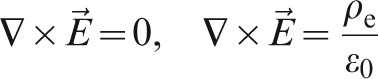
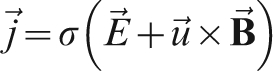
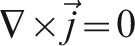
The electromagnetic processes in liquid metal can be described by Maxwell’s equations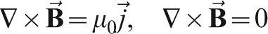


The heat parameters are calculated by heat transfer equation
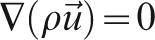
The hydrodynamic processes in the liquid can be described by Navier–Stokes equation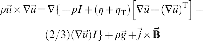


According to the preliminary estimation, the Reynolds number under the movement in dc steel making furnace is Re = u
0
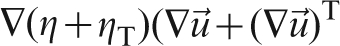
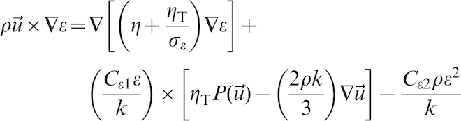
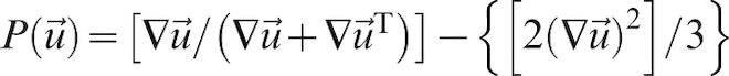
L/ν≈106, which is equivalent to the developed turbulent flow that can be described within k−ϵ turbulence model. The equations of k−ϵ turbulence model are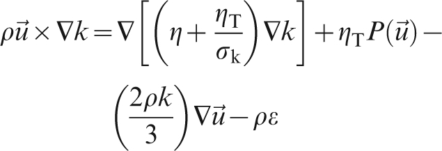
Strategy of solution of multiphysics problem
The problem in question has no analytical solution, and therefore, it was solved numerically. As a result of the numerical solving methods analysis, the finite element and finite volume methods and its software realisation in ANSYS Multiphysics, 7 ANSYS CFX 8 and COMSOL 9 are chosen. The problem belongs to the class of multiphysics, and the strategy of solution consists of the following stages:
first stage: solving electromagnetic fields
second stage: solving heat processes
third stage: solving EVFs with the account of heat exchange and convection.
Model of industrial furnace
To build a model of the processes in an electric steel furnace, it is necessary that the parameters of the industrial dc arc furnace with bottom electrode should be taken into account. These parameters were described earlier, and the geometrical arrangement of the furnace is shown in Fig. 2. The main parts of the configuration are as follows: refractory, liquid metal, top and bottom electrodes and air. Axial symmetry allows calculating half of the axial cross-section area.
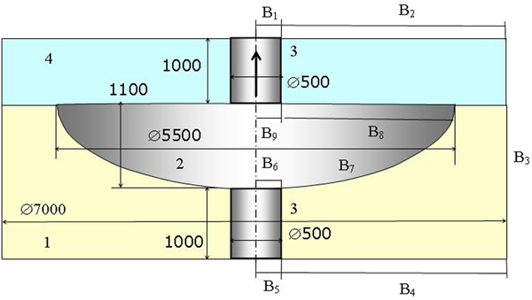
Arrangement of cylindrical dc arc furnace (1: refractory; 2: liquid metal; 3: electrodes; 4: slag)
The formulated problem was solved with the corresponding boundary conditions that are defined in Fig. 2 as B1–B9 and presented in Table 1.
The current density on the boundary with normal cross-section of electrode j n = j 0 = I/S, where S is the cross-section of the electrode. For the electric and magnetic fields, the conditions of continuity are used. The heat boundary conditions are represented by constant temperature of electric arc, bottom electrode, boundary with slag and with refractory. 1,2,4 A no slip boundary condition was used for hydrodynamic processes on all liquid boundaries, both on the boundary of the liquid with the refractory and the boundary of liquid with slag. The last approximation is based on the fact that slag viscosity is much higher than liquid metal viscosity, and it can be considered as a no slip condition. For all types of analysis on the axis symmetry of the calculation domain, the axis symmetry condition was used.
In the model, the following physical data for liquid steel, electrodes and refractory were used: electric conductivity of liquid steel does not change significantly with the temperature; it changes only by 9% from 1550 to 2730°C and was taken as σ 1 = 0·712×106 (OM.M)−1 at 1750°C; electric conductivity of electrodes σ 2 = 0·2×106 (OM.M)−1; relative permeability and relative conductivity of the media, electrodes and liquid steel μ = 1 and ϵ = 1; specific heat for 1500–2000°C is C p = 750 J kg−1 K−1; thermal conductivity for 1500–2500°C is a = 32 W m−1 K−1. The density and viscosity were used as set functions of temperature that are given as tabulated values. 10 The k−ϵ turbulence model constants Cμ = 0·09, Cϵ 1 = 1·44, Ck 2 = 1·92, σ k = 1·0 and σϵ = 1·3 were chosen.
The calculations were carried out with the use of different meshes and types of analysis. At every stage of the solution, a separate computational mesh was built. The type of analysis and boundary condition shown in Fig. 2 correspond to the solution stage according to strategy of solution of multiphysics problem. At the first stage of modelling processes in ANSYS Emag (electromagnetic analysis), the size of mesh elements was selected in such a way so that the decrease of the size does not change the calculation results. In the parts of the domain area with the large gradients of the parameters, the grid cells decreased, while in the parts with the smaller gradients of the parameters, they increased. According to which, the size of calculation mesh cells at the electrodes should not exceed 0·07 of the typical calculation domain size (the electrode radius).
The calculation mesh in ANSYS CFX for solving hydrodynamic parameters, namely, at the second and third stages, was built separately taking into account all parameters given before. Furthermore, the special features of hydrodynamic processes were taken into account.
For all types of analysis, both triangular calculation mesh cells and rectangular ones were used. While solving the electromagnetic parameters, it was found out that the difference between the triangular and rectangular mesh shapes was not significant. At the stage of solving the hydrodynamic parameters, the significant differences of the results obtained on the meshes with the different shape of the cells were found. To achieve similar results for the triangular and rectangular mesh shapes, the triangular cell mesh should be half the size of the rectangular ones.
The preliminary analysis provided the optimal division into elements, as well as their form. The domain area was split into elements unevenly: in the area of the electrodes and boundary with refractory, where the large gradients of all parameters are situated, elements were densely located and were of small size ∼0·01 of the electrode radius. At the other parts of the calculation domain, the elements were not densely located and were of large size (∼10 times larger). The calculation mesh was built according to speciality of the physical processes in dc arc furnace. At the preliminary publication, 11 the calculations were made for plane axial symmetry [two-dimensional (2D)] as well as for three dimensions (3D). The differences of the results obtained at 2D and 3D formulation ranged from 1 to 3%, but the time of the calculation for 3D formulation increased several times, as compared with 2D formulation.
In the COMSOL software package, all three stages are calculated with the use of only one calculation mesh to achieve the given accuracy of the results. The size, shape and approximate arrangement of cells in computational mesh corresponded to the calculation mesh in ANSYS.
Results of solution and discussion
Some results of solving the processes occurring in the liquid steel are given below. Figure 3 demonstrates the vector and contour fields of the Lorentz force near the bottom electrode (anode). The value of Lorentz force ranged and upon the average comprised ∼30% of volumetric gravity force. The results of the calculations show the fact that the Lorentz force in such furnaces is essential for the appearance of EVF. 11,12
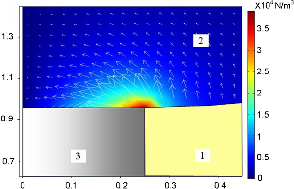
Vector and contour field of Lorentz force near the bottom electrode (1: refractory; 2: liquid metal; 3: electrodes)
The velocity field for isothermal formulation, when the power is insignificant and only compensates losses through the refractory based on the obtained results of electromagnetic force, was calculated in a previous publication. 13 The calculations were carried out in both 2D and 3D formulation. 13,14 The good coincidence of electromagnetic and hydrodynamic parameters at the same distance from electrode for 2D and 3D formulation makes it possible to carry out calculations in 2D axial symmetry formulation only.
The vector, contour field and streamlines of velocity without convection are given in Fig. 4 and show that the higher intensity of vortex movement appears in the liquid metal volume. The vortex arises near the bottom electrode and is directed upwards. When the flow achieves the upper boundary of the liquid metal, it flows along the boundary and then back downwards. The figure shows that at the top electrodes, an inverse vortex flow appears. The maximum value of the vortex flow velocity is located on the axis symmetry and reaches 0·3 m s−1. The vortex flow velocity value in close proximity to the bottom electrode and the refractory is ∼0·1 m s−1.
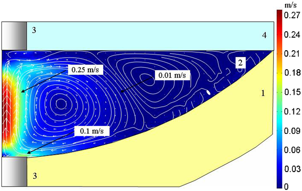
Vector, contour field and streamlines of velocity without convection (1: refractory; 2: liquid metal; 3: electrodes; 4: slag)
In the next stage, the heat and hydrodynamic processes in the liquid metal were modelled in axial symmetry formulation. In Fig. 5, the temperature field throughout the liquid metal is demonstrated. As can be seen, the maximum temperature is located near the cathode (top electrode) at a distance of about the electrode radius. The temperature profile shows that there is a radial gradient that produces the convective flow in electrovortex movement as shown in the previous work. 6 Moreover, the direction of convection flow depends on the arithmetical sign of the temperature gradient: if the gradient is negative (∂T/∂r<0), the circulation is clockwise, but when the gradient is positive (∂T/∂r>0), the circulation is counterclockwise. In the first case, the convection flow will be in the line with EVF and will increase it, but in the second case, the vortex movement will decrease.
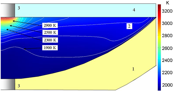
Contour field and streamlines of temperature (1: refractory; 2: liquid metal; 3: electrodes; 4: slag)
The hydrodynamic fields of velocity vector, contour and streamlines are given in Fig. 6, which demonstrates that the higher intensity of vortex movement appears in the liquid metal volume. The convection flows are in the line with EVF, and electrovortex movement increases. The vortex arises near the bottom electrode, as Fig. 6 shows. The vortex flow of liquid metal on axial symmetry axis is directed upwards. When the flow achieves the upper boundary of liquid metal, it flows along the boundary and then downwards. The maximum value of the vortex flow velocity was located on the axis symmetry and reaches 0·5 m s−1, within is ∼1·5 times more than the movement without convection. The vortex flow velocity value in close proximity to the bottom electrode and the refractory comprises ∼0·3 m s−1. According to the figure at the top electrode area, the inverse vortex flow appears. This vortex is produced by the uneven distribution of current density near the top electrode.
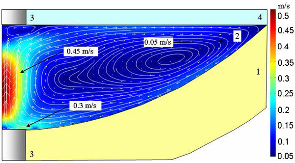
Vector, contour field and streamlines of velocity with convection (1: refractory; 2: liquid metal; 3: electrodes; 4: slag)
When the convection flows are taken into account, all the volume of liquid metal is drawn into the vortex movement, i.e. without a stagnation region near the furnace walls, which can be seen clearly in Fig. 4 for the liquid movement without convection flows. Moreover, the vortex near the top electrode decreases. The dominating contribution to vortex flows is made by the Lorentz electrovortex force. Taking the convection flows into account leads to the increase of maximum velocity value of liquid vortex movement one-third times in comparison with velocity of EVFs under Lorentz force only.
Verification of obtained results
Reliability and accuracy of the calculated results were estimated by comparing these results with:
theoretical researchers
experimental data obtained with the laboratory installation
calculations performed by other methods and software packages
experimental data based on the increased wear of the bottom electrode for an industrial dc electric arc furnace.
A comparison of the obtained results with theoretical researches of liquid metal movement in model tasks was carried out. The character of the liquid movement obtained in numerical modelling conforms to the general theoretical assumptions that are given in the physical statement of the problem and described in previous works. 1–4,6,15,16 According to the theory, when the current flows through the molten metal, a magnetic field is generated. The current conductor in the magnetic field is affected by the Lorenz force. Spatial unevenness of the current leads to the vortex character of the Lorenz force, according to the geometry of the furnace and the electrode location. Under the influence of this force, the elements of liquid move as a whole towards the resultant force vector, and hence, vortex flow appears. The maximum intensity of the vortex movement is found near the bottom electrodes where the value of the rotational Lorenz force module is maximum.
Initially, during debugging, the modelling methods, the laminar EVF problems in half-sphere that have the solution, 6 were solved. The character of the movement and velocity distribution on the symmetry axis are compared. The difference of the solution for the velocity comprises <2% that proved the reliability of the physical and mathematical model as well as the strategy of solution.
Then, the calculations were performed for the turbulent flows that had been studied experimentally with the use of a laboratory unit. 16 This type of EVF does not have a clearly presented boundary or strike slip layer. Therefore, the choice of an adequate turbulence model during turbulence EVF simulation is an important problem. During the calculation, different turbulence models were used. The acceptable results that correlate with experimental data within 15% limits (in turbulent fluctuation level) were obtained for k−ϵ turbulence model that was used in further calculations. The physical processes in laboratory installation, comparison of the experimental and numerical results are given in Fig. 7.
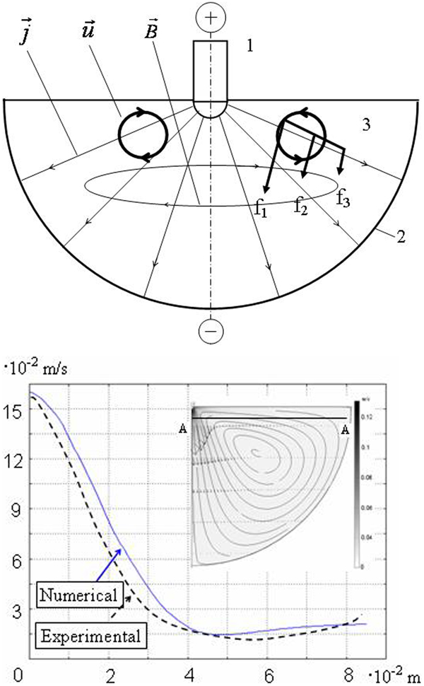
Physical processes in laboratory installation and numerical results (1 and 2: electrodes; 3: liquid eutectic alloy)
To verify the obtained results, similar calculations were performed in COMSOL. The comparison of the obtained results by different software packages and methods showed an insignificant difference of ∼3%. 11–15 The similarity of the calculations performed by different methods and software packages confirms the reliability of the methods and significance of the results.
According to the general theoretical conceptions and the recent research, 17 there is a connection between shear stress on the refractory from the velocity of the liquid and the increased refractory wear. The increased wear configuration of the bottom electrode and the refractory near the bottom electrode after 400 heats is given in Fig. 8. 5 These data have been obtained since 1996 by checking the actual wear periodically throughout the life of several dc electric arc furnaces: ‘Balboa’ (Spain), 70 t; ‘Hylsa Planos’ (Mexico), 135 t; and ‘ABC Danarc Plus’ (Italian), 90 t. The increased wear of the bottom electrode and refractory right near the bottom electrode confirms that the flows with higher velocity and maximum value of the friction force are located near the bottom electrode at a distance of about the radius of the electrode. The conical shape of the refractory border near the bottom electrode shows that the liquid vortex flow is of conic character and the washout of refractory right near the bottom electrode indicates that streamlines of liquid movement under Lorenz force are produced and finished on the bottom electrode. This characteristic of the refractory wearing confirms that the major cause of the increased wear is liquid vortex movement under the Lorenz force.
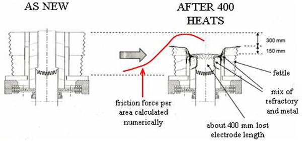
Configuration of increased wear of bottom electrode and refractory near the bottom electrode
The verification of the results has shown a good correlation with the general theoretical data concerning electrovortex movement, the results obtained by other authors, as well as a good correlation with the experimental data for both laboratory installations and industrial dc arc furnaces. All of that has proved the reliability of the methods and approaches, as well as the accuracy of the obtained results.
Conclusions
A mathematical model of processes in dc arc furnace has been built. To describe the processes in the electric furnace, the model of the magnetic hydrodynamic was adopted. It takes into account the spatial distribution of the current, electric and magnetic fields, temperature, the Lorenz force, the Joule heat and convection. The strategy of solving the stated conjugate problem in standard software packages is worked out. Numerical modelling of magneto hydrodynamic processes in liquid metal for dc arc furnace is carried out.
It was established that the volumetric Lorentz force makes up ∼30% of the volumetric gravity force and is essential for the vortex flow appearance, the maximum value of which reaches 0·5 m s−1. The comparison of the results for isothermal and non-isothermal liquid showed the main contribution of electrovortex force and significant contribution of convection flows with the maximum heat power of furnace.
The results of the calculations in ANSYS Multiphysics and ANSYS CFX were compared with the experimental data, calculations in COMSOL and general theoretical conceptions. Similarity of the calculations performed by different methods and experimental data proves the reliability of the methods and significance of the results.
The developed models, methods and approaches were used to estimate the effect of different factors on liquid metal movement intensity and increased wearing of the refractory. These results can be used to improve the furnace work and reduce the cost of service.