
Abstract
Surface transverse cracking, especially corner cracking, is prone to generate in continuously cast slabs of microalloyed steels. The method of surface structure control (SSC) was supposed to the best way to avoid the detrimental defects. However, the mechanism of improving hot ductility by SSC and the specific parameters to control the process are still unclear for the reasonable adoption in production. In the present work, the impact of cooling rate, holding temperature and holding time on austenite decomposition, and the austenite grain size before and after intense cooling were investigated by thermal simulation method. With the increase of cooling rate, it is observed that the phase is transformed from austenite → grain boundary film-like alltromorph ferrite → Widmanstätten ferrite plates (or intragranular ferrite plates) → bainite+martensite. Mostly important, the film-like ferrite can be eliminated through intense cooling and the following reheating, but the austenite grain size is not observed to be refined through the single γ → α → γ cycle. Even though, the reduction of area (RA) is improved drastically to over 70% in the third ductility trough, whereas the RA value is just < 40% for the conventional cooling. The reason can be deduced by eliminating grain boundary film-like ferrite, and carbonitrides were precipitated inside the grain, which simultaneously act as the nucleus of intragranular ferrite. Thus, the principle of SSC process was established, and based on heat transfer calculation, water flow adjustment was put forward to implement the intense secondary cooling, which is a meaningful exploration for reducing transverse cracking.
Introduction
Surface and corner transverse cracking frequently arises in continuous casting of microalloyed steels, which was mainly caused by the following reasons. a) The carbonitrides of microalloyed elements (Nb, V, Ti or Al) and film-like proeutectoid ferrite that precipitated along the austenite grain boundary during austenite to ferrite transformation temperature, deteriorating the hot ductility of matrix at elevated temperature. If the strand is bending or straightening at this ductility trough, cracking that initially occurred along the prior austenite grain boundary is prone to propagate by stain concentration. 1 b) In addition, the formation of these cracks has been attributed to large austenite grain, which generated near the surface region at the root of the deep oscillation mark due to the uneven solidification in the mould, 2–4 especially for peritectic steels, 5,6 thus increasing the tendency to form film-like ferrite along the austenite grain boundary 7 that makes it more sensitive to cracking. c) Moreover, unsuitable mould powder and unreasonable oscillation will cause the deep mark to promote surface cracking, and misalignment of pinch rolls will increase the amount of strain, which can lead to cracking on the surface, albeit those are not the decisive factors.
The most common way to reduce the defect is to avoid temperature from falling into the poor ductility range during unbending. However, owing to the non-uniform thermal profile across the slab width, particularly at the corners, 8 as the fact we all accepted, the temperature of which is inevitably in the brittle temperature range. Aimed at eliminating the trouble thoroughly, Schmidt and Josefsson 9 were the pioneer to refine the surface microstructure by γ → α → γ transformation through intense secondary cooling. Based on this, a new secondary cooling method was proposed by Kato et al. 10–13 and Walmag et al. 14,15 The mechanism of the process can be outlined below: an intense cooling out of the mould was adopted to eliminate the film-like grain boundary alltromorph ferrite during austenite decomposition, after which the surface structure will change to austenite again by self-reheating through the release of latent heat. Ferrite or other structure transformed from austenite will resolve during reheating, whereas the prior carbonitrides precipitated will not dissolute, acting as the nucleus of subsequent austenite decomposition products. Then, a fine and uniform structure will be generated from austenite within the following mild cooling, thus enhancing the hot ductility of the brittle range.
Nevertheless, the mechanism and some detailed operating parameters have not been clear yet, making it difficult to implement into industry production. Taking the holding temperature for instance, Kato et al. 10 noted that it should cooled below A3 temperature at least, while Ma et al. 8 and Lee et al. 16 held the opinion that the value must be below Ar3. Walmag et al. 14,15 and Lee et al. 16 both indicated that the austenite grain size had been refined after the process, but Kato et al. 10 and Suzuki et al. 17 asserted that the strain during continuous casting was not enough to cause dynamic recrystallisation, and grain size can be refined only by repeated γ → α → γ transformation rather than one single cycle. 18
Consequently, in this paper, hot ductility test was carried out to illuminate the mechanism and principle of surface structure control (SSC) as follows. a) Some parameters affecting the phase transition and the extent were investigated, such as cooling rate, target cooling temperature, holding time, reheating condition, etc. The optimum process parameters for typical Nb alloyed steel were obtained, and meanwhile, the principle of SSC was confirmed, which could be referenced for other similar steel grades. b) Whether the austenite grains are refined or not was explored after intense cooling. c) Combined with the dynamic secondary cooling system, the temperature profile of the slab was calculated, and secondary cooling adjustment was made to investigate the feasibility of SSC.
Experimental
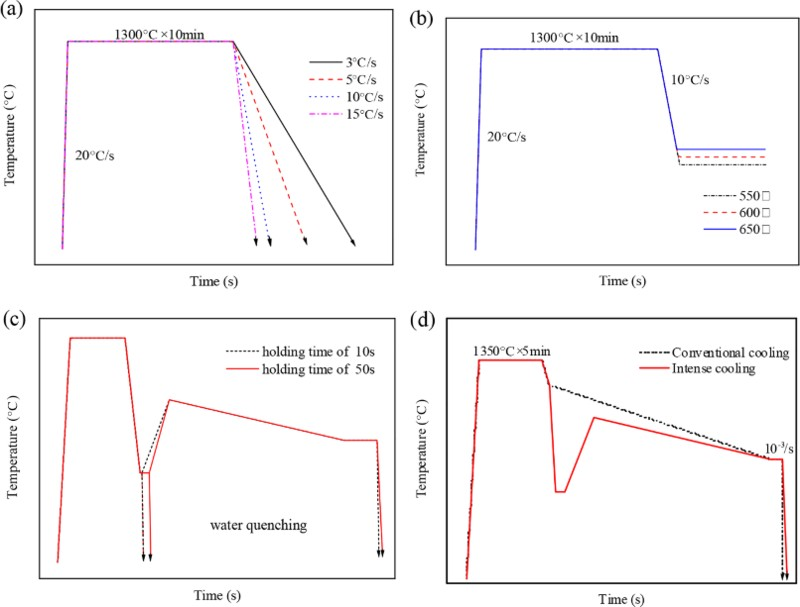
The composition of tested steel (typical Nb bearing microalloyed steel) is shown in Table 1. Specimens cutting from continuously cast slab were machined to two shapes, the ones ∅4 × 10 mm for thermal expansion test and the others ∅10 × 120 mm for hot tensile test. Specific experimental scheme is illustrated in Fig. 1. The decomposition temperature Ar3 was determined at different cooling rates (3, 5, 10 and 15°C s− 1 respectively) by utilisation of DIL805 thermal dilatometer. The corresponding transformation products from austenite were inspected via optical microscope. Survey was carried out on the austenite transformation reaction with different thermal expansion curves in terms of various target cooling temperatures at 650, 600 and 550°C under selected cooling rate from test (i) after austenitisation. The metallographic structure by means of water quenching at holding temperature after holding for 10 and 50 s, as well as the end of mild cooling, was observed. Thus, the influence of holding time on microstructure evolution could be figured out. The appropriate holding temperature was chosen from test (ii). By integrating the above results, a suitable principle could be made for SSC. Then, the reduction of area (RA) value was measured, after which the difference of RA values of specimens with and without the SSC method can be compared. Observation was implemented on the fracture surface morphology with electron microscope and the metallographic structure under optical microscope after ripping the fracture along the stretching direction and etching the samples with nitric acid alcohol. The distribution of precipitated carbonitrides was examined with field emission scanning electron microscope (FE-SEM).
Composition of tested steel, wt-%
a microstructure evolution at distinct cooling rate for 3, 5, 10 and 15°C s− 1
In addition, the austenitic grain size before intense cooling and after self-reheating at 1000°C was compared in order to identify whether it was austenite grain size refinement that improved the hot ductility during the new secondary cooling process. As the reheating temperature must exceed Ac3 and the reheating rate as well as the reheating temperature have little effect on hot ductility, 1000°C was determined as the reheating temperature in this test.
Result and discussion
Austenite transformation structure at different cooling rates
On account that the cooling rate will change the morphology and position of precipitates and ferrite not only under intense cooling but also in the subsequent mild cooling process with the microstructure experiencing a re-austenitisation, it is necessary to study austenite transformation products under different cooling rates. 8 Experimental schematic and results are shown in Figs. 1a and 2.
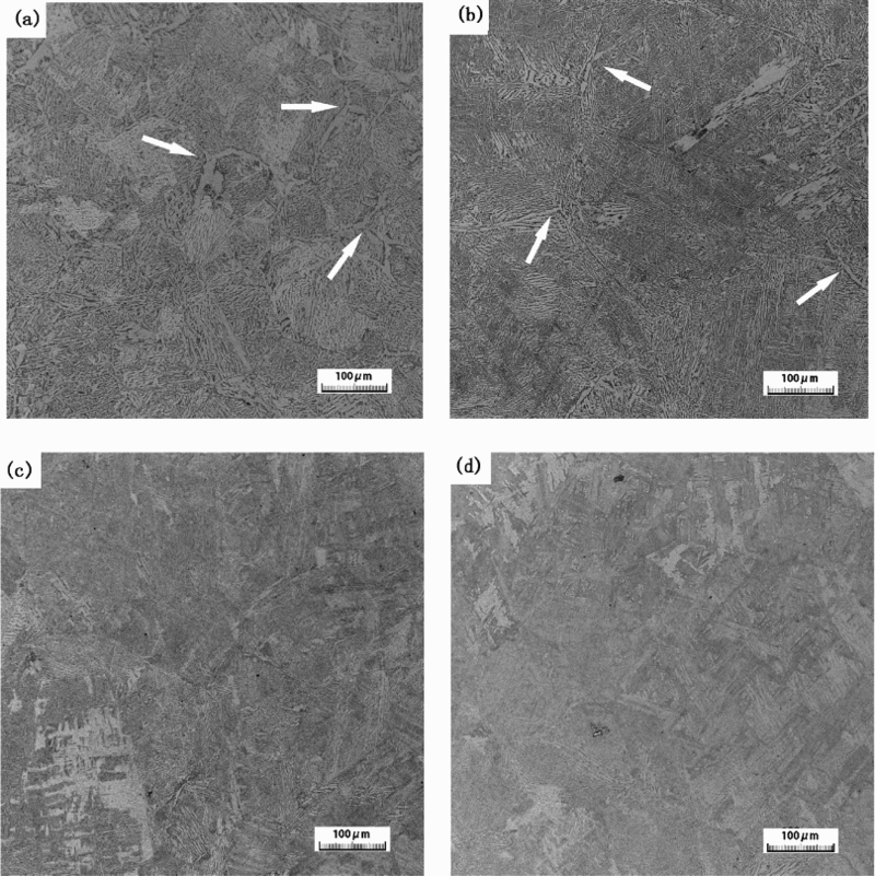
a 3°C s− 1; b 5°C s− 1; c 10°C s− 1; d 15°C s− 1
As seen in Fig. 2, in contrast with the morphology classification of ferrite from γ → α transformation studied by Aaron and Aaronson 19 and Honeycombe and Bhadeshia 20 at the cooling rate of 3°C s− 1, the structure is film-like alltromrophy ferrite along the grain boundary and intragranular pearlite; for 5°C s− 1, it turns to be less grain boundary film-like ferrite and Widmanstätten ferrite plate (or intragranular ferrite plates) and pearlite; when the cooling rate is increased to 10°C s− 1, with higher supercooling degree, film-like ferrite disappeared, and the amount of intragranular Widmanstätten ferrite plates and bainite abundantly arise; as to 15°C s− 1, the structure transforms to bainite and martensite totally.
From the analysis above, with the increment of cooling rate, film-like proeutectoid ferrite is transformed to intragranular Widmanstätten ferrite plates, and simultaneously, ferrite and pearlite are replaced by bainite and even martensite. With regard to the tested steel, 10°C s− 1 is enough to eliminate the grain boundary film-like ferrite, meeting the requirement of SSC.
Impact of cooled temperature on structure evolution
The expansion curve will go upward when the phase transition from austenite starts, 21 because the specific volume of whatever transformed phase (ferrite, pearlite, bainite or martensite) is larger than austenite due to its body centred cubic crystalline structure. Tests and outcome are illustrated in Figs. 1b and 3. The arrows in Fig. 3a indicate the starting transformation point of austenite. When the holding temperature is 650°C, the speed of phase change is relatively low. The thermal expansion curve does not rise until 40 s of holding time passes, which indicates that the incubation period is about 40 s. Hereafter, the phase is changing slowly until the end of holding temperature process. With the reduction of holding temperature decreasing from 600 to 550°C, the incubation period shrinked to 10 and 5 s separately due to better thermodynamic condition, as displayed in Fig. 3b . In the case of cooling to 550°C at 10°C s− 1, the expansion lasts around 30 s after holding for just 5 s, asserting that austenite is thoroughly transformed within 35 s. In addition, in this case, the cooled temperature 550°C is not below the Ar3 temperature,of which the tested steel grade is 528°C. Thus, we should speculate that it is not prerequisite to cool below Ar3 but rather a little bit higher than the Ar3 temperature according to the reality of casting conditions, as sometimes it is hard to implement that intensive cooling to each caster or each steel grade. Here, for this circumstance, the optimum cooled temperature is 550°C.
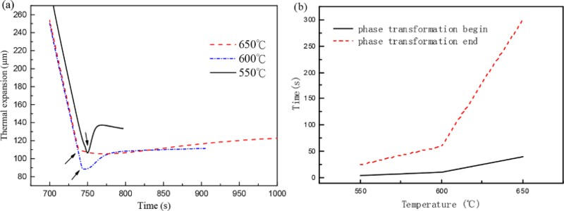
a thermal expansion during isothermal holding at different temperatures in cooling process (arrows indicate starting resolve point of austenite) and b begin and end time of phase transformation of holding temperature for 550, 600 and 650°C
Holding time
For the sake of manifesting the evolution of the microstructure during the holding process, the samples were quenched after holding for both 10 and 50 s at 550°C. By observing the structure and morphology depicted in Fig. 4, the former is martensite with a small amount of upper bainite, while the latter is upper bainite and granular bainite. It can be concluded that austenite transformed thoroughly with the increase of holding time.
a 10 s; b 50 s
Generally, the more thorough the phase change is,the larger the amount of precipitated carbonitride will be, as the solubility of precipitation is smaller in ferrite and other phase than in austenite. Actually, no matter what and how the austenite transformed during the isothermal holding period, the transition product will reaustenitise within the self-reheating process driven by the release of latent heat. Nevertheless, precipitated carbonitrides will not redissolve in time, which will act as the core of nucleation of intragranular ferrite during the subsequent mild cooling. The influence of precipitation behaviour of carbonitrides on ferrite nucleation was explored in Ref. 22.
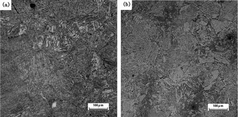
It is still unknown how the intermediate parameter may affect the final structure after the whole cooling process. Thus, the tests in Fig. 1c were carried out under a cooling rate of 10°C s− 1, with samples cooled to 550°C, reheated to 1000°C after holding for 10 or 50 s and quenched at 750°C after mild cooling. Results of metallographic structure are shown in Fig. 5.
Final microstructure with isothermal holding procedure for a 10 s and b 50 s: arrows in a indicate grain boundary film-like allotriomorph of ferrite
The microstructure with holding time of 10 s, shown in Fig. 5a , is almost martensite with a small amount of grain boundary ferrite, while with holding time of 50 s, shown in Fig. 5b , it is uniformly ferrite and pearlite with much less martensite. The austenite does not decompose completely during the short holding time of 10 s, having fewer carbonitride precipitated correspondingly. Albeit the metastable state, austenite can still be transformed in the reheating process, and the decomposition product tends to nucleate intergranularly rather than intragranularly by reason of the decline of driving force with the temperature increment. 23 Thus, after holding for 10 s, ferrite would mainly nucleate at the grain boundary, which needs less nucleation energy, or at the location of a small amount of carbonitrides inside the grain. After holding for 50 s, intragranular idiomorph ferrite dispersed homogeneously since the austenite is transformed thoroughly after isothermal holding and a large amount of carbonitrides precipitated inside the prior austenite grain act as the nucleus during the succeeding mild cooling.
The principle for SSC could be finally obtained from the above experimental results and analysis. The basic rule of SSC for this tested steel grade is intensely cooled to 550°C immediately after exiting the mould at a cooling rate of 10°C s− 1, held for 50 s, reheated to around 1000°C and then mildly cooled as usual.
Austenite grain size
Austenite grain size was compared with and without SSC process by quenching the specimens at 1000°C before and after γ → α → γ transformation. Specimens were etched with saturated picric acid plus a little detergent, 24 and the metallographic structure is shown in Fig. 6. Measurement showed that the average grain size is 100 and 150 μm approximately. Even after a γ → α → γ transformation, the austenite grain grows a little bit rather than be refined, which is not consistent with some former investigation. 14–16 Consequently from this test, austenite grain cannot be refined by a single γ → α → γ cycle.
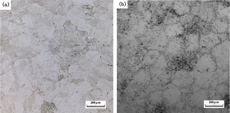
Grain size evolution after microstructure treatment a before cooling and b after reheating
Hot tensile test
The ultimate purpose is to prevent surface cracking by improving hot ductility. Therefore, hot tensile test was conducted by a Gleeble 1500 and fractograph; metallographic structure and carbonitrides were observed as well.
As illustrated in Fig. 1d , the samples were heated to 1350°C for solution treatment, then cooled to target temperature and were deformed until fracture at a strain rate of 10− 3 s− 1 similar to continuous casting. Hot ductility curves are gained and plotted in Fig. 7 for both cooling strategies. As shown, the RA values of conventional mild cooling between 700 and 900°C are almost all < 60%, with the lowest ∼29% at 750°C, making cracks occur easily. However, when the SSC process is introduced, the RA values all markedly rise to >70%, with the one at 750°C reaching 74.9%, realising a significant improvement of hot ductility.
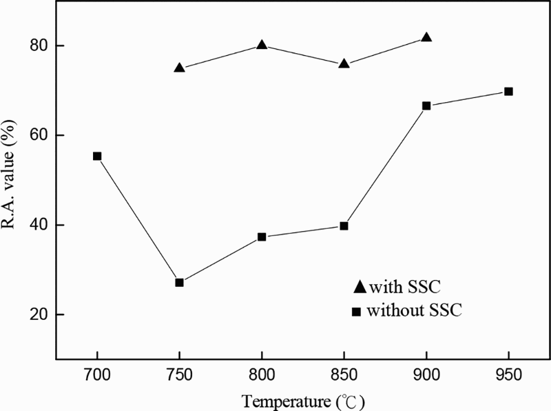
Hot ductility curve with and without microstructure control
Figure 8 illustrates the distinct fracture morphology of two samples. As can be seen, it is transgranular fracture (Fig. 8a ) with SSC whose surface is full of dimples, while the intergranular fracture surface (Fig. 8b ) is rock candy structure under conventional continuous casting.
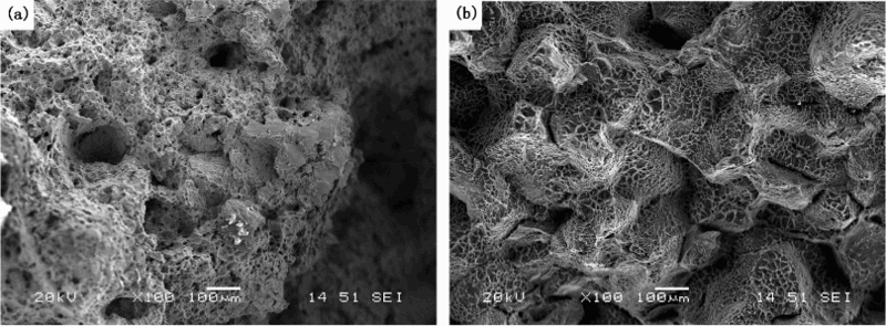
Fracture surface a with and b without microstructure control
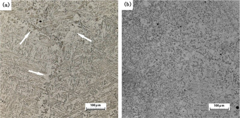
The metallographic structure near the fracture surface is shown in Fig. 9. In Fig. 9a , the holes generated by stretching are not concentrated at one point, and uniform ferrite is dispersed in the matrix with the SSC process. As shown in Fig. 9b , as a contrast, film-like alltromorphy ferrite is abundantly eutectoid along the austenite grain boundary, the thickness of which reaches 20–30 μm. Cracking is prone to arise by stress or strain concentration at the feeble film-like ferrite. Accordingly, the microstructure is optimised by SSC.
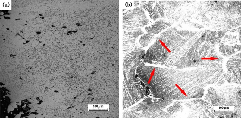
Microstructure a with and b without microstructure control: arrows in b indicate grain boundary film-like allotriomorph of ferrite
The morphology of carbonitrides at fracture is shown in Fig. 10. The square particles spreading inside the dark ferrite, whose size is between 50 and 200 nm, are a mixture of carbonitride of Ti and Nb as confirmed by energy disperse spectroscopy, as shown in Fig. 11. In addition, the formation of compound Ti,Nb(C,N) in Fig. 11 can be interpreted as follows. The starting precipitation temperatures of TiN and Nb(C,N) were ∼1400 and 1100°C, as calculated by the thermodynamics of titanium and niobium carbonitrides. Consequently, the TiN first precipitate from austenite and become the nucleation site of Nb(C,N) during the secondary cooling process. As prior research 22,25 has proved, with higher cooling rate, the amount of precipitation will be reduced, and they will disperse uniformly inside the grain rather than chain-like along the grain boundary. It can be seen that these compound titanium and niobium carbonitrides in Fig. 10 give the same result.
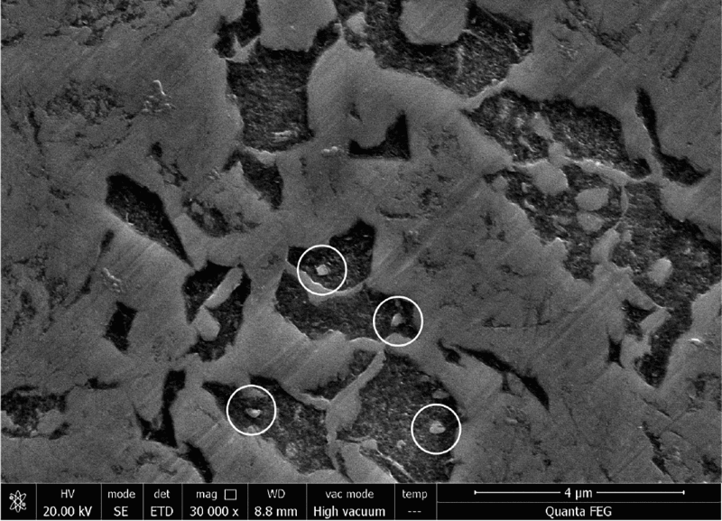
Image (FE-SEM) of precipitates (indicated by circles) inside ferrite
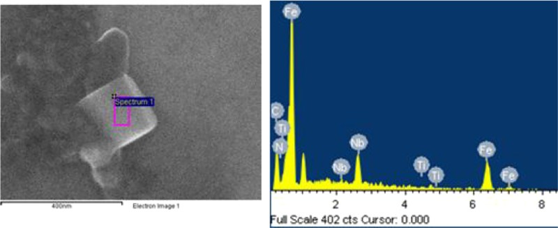
Energy disperse spectroscopy spectrum of precipitates found in ferrite
For the effect of the precipitates on ferrite formation, from the earlier experiments conducted by Riaz et al. 26 it seems that all types of precipitate (TiN, Ti,Nb(C,N), MnS, Al2O3, SiO2) can become a potential site for nucleation of ferrite, and idiomorph ferrite nucleates heterogeneously inside the austenite grain preferably on non-metallic inclusions and precipitates. The dark ferrite in Fig. 10 proved that again.
Given all that, the conclusion can be drawn that the real reason for the third hot ductility trough elimination by a single γ → α → γ cycle is not austenite grain refinement but the intragranular ferrite and precipitates inside the grain as a result of removal of film-like grain boundary ferrite and chain-like grain boundary precipitates.
Guidance to industrial application
The new secondary cooling strategy of SSC to improve the surface quality of semi- or final product has triggered enormous attention and has been put to pilot trails. 13,27 The arrangement of the intense cooling zone of continuous casting machine is shown in Fig. 12. The temperature field of the slab surface width centre for tested steel was simulated by dynamic secondary cooling model 28 with and without SSC. For the conventional cooling process, the temperature is around 900–1000°C at the straightening point (∼16.8 m from the meniscus), and the corner temperature is likely to drop to < 900°C, which strongly increases the cracking susceptibility.
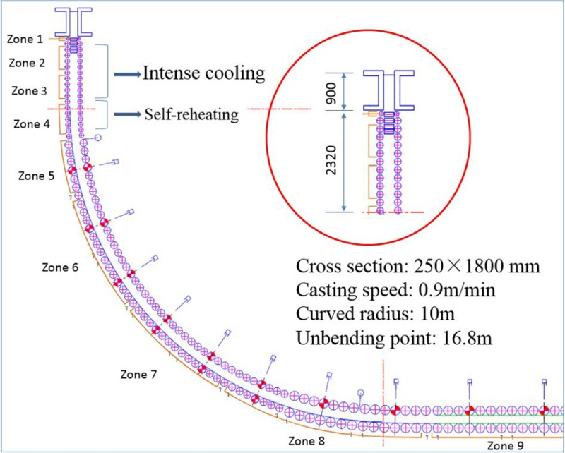
Arrangement of intense secondary cooling zone in simulation of slab casting
According to the principle we made currently, intense cooling was implemented at the vertical section (zones 2–3), while the flowrates of other sections (zones 4–9) remain unchanged. Optimised water flowrate is shown in Table 2. By enforcing water flow of the spray zone 2, temperature declined to approximately 550°C at a cooling rate of around 10°C s− 1. Afterwards, the temperature will be held at 550°C for ∼1 min due to the flowrate enhancement of the spray zone 3 with the balanced heat exchange between released and transmitted. It is ensured to avoid the surface temperature from the third ductility trough during bending. With releasing latent heat inside the slab, the surface temperature was reheated to 900°C at a rate of 5°C s− 1 after bending. Through the subsequent mild cooling process, the cracking susceptibility could be minimised with the improvement of surface structure even at the straightening point when the temperature drops to the conventional low ductility zone.
Comparison between conventional and intense cooling condition
Conclusions
With the increase of cooling rate, sufficient supercooling is achieved, and the phase is transformed form austenite → grain boundary film-like alltromorph ferrite+pearlite → Widmanstätten ferrite plate (or intragranular ferrite plates) + pearlite → bainite+martensite, and most importantly, the film-like ferrite can be eliminated. According to the flexibility of the real casting condition, the surface temperature could be intensely cooled to a little bit higher level rather than the lower Ar3 temperature because phase transformation will still take place with enough holding time even at relatively higher temperature. Of course, the lower the cooled temperature with longer holding time, the more sufficient phase transition and finer the final structure, as long as the kinetic condition permits. The austenite grain is not refined through single γ → α → γ cycle, which proves that it is not austenite grain refinement that alleviated cracking susceptibility, but the film-like grain boundary ferrite elimination and intragranular carbonitride precipitation. For the tested Nb bearing steel, cooling to 550°C at 10°C s− 1, holding for 50 s is the relatively optimum parameter that can remarkably improve the ductility to prevent surface cracking. By conducting the numerical simulation, it is indicated that intense cooling and temperature preservation required by the SSC process could be realised by adjusting the secondary cooling profile. Based on this, the reference optimised water flowrate is given for the tested Nb bearing steel.