
Abstract
Titanium aluminide alloys offer considerable promise for use in high temperature applications, such as gas turbines. In this study an extruded Ti–46Al–5Nb–1W alloy has been examined, in terms of its tensile and creep behaviour. A reasonably fine and uniform microstructure was found in this bar product. This gave excellent properties, with tensile strengths up to ∼950 MPa at room temperature, along with 1 elongation. These properties were accompanied by a very good creep behaviour, with low primary strains at the lower stresses and very low secondary creep rates. Comparison of the creep properties of this titanium aluminide alloy with other similar compositions and some typical nickel alloys shows that it is significantly superior to first generation titanium aluminides but also nickel alloys, such as IN718 and Udimet 720Li. However, the strain controlled fatigue performance of the titanium aluminide alloy was significantly poorer than these same wrought nickel alloys.
Keywords
Introduction
For gas turbine manufacturers the principal factors driving developments are cost, environmental concerns, fuel efficiency, the use of biofuel and, for the aerospace sector, the thrust/weight ratio. These factors can be improved by either reducing the rotating mass directly, or by increasing the mass flow through the engine core (for biofuel usage). This latter issue may be assisted by utilising low mass blades to control the stresses on the disc. Thus there remains a drive to reduce the density of materials used in gas turbines, especially in aerospace. The low density gamma titanium aluminide (γ-TiAl) alloys are particularly attractive because they offer significant weight reductions, of up to 40 for components, when replacing the steels or nickel superalloys currently used.
Early gamma titanium aluminides, such as Ti–48Al–2Cr–2Nb, gave relatively low strength (∼470 MPa at room temperature), even after hot working,1 but developments over the last decade have produced alloys with significantly higher strength levels. A particular group of these higher strength alloys has been those containing relatively high levels of niobium additions (4–10 at-) and these materials have become the focus for much of the industrial interest in this class of material.2,3 Alongside the alloy development for high strength, there has also been considerable interest in developing these alloys for improved creep performance and here the addition of tungsten has been shown to be particularly beneficial, for example with alloys such as Ti–47Al–2W (known as ABB-23).4,5
The work reported here has examined an alloy combining both the niobium and tungsten additions (Ti–46Al–5Nb–1W) and also processed by extrusion to obtain high strength. This alloy composition has been evaluated previously following production from either a cast6 or a forging route.7 Therefore, the work here provides a further commercial production route that can be compared with this composition. In addition, the mechanical performance of the extruded Ti–46Al–5Nb–1W (at-) (Ti–46–5–1) alloy has been compared with other competing γ-TiAl compositions and the opportunity has also been taken to re-evaluate these materials in comparison with other materials systems (e.g. nickel alloys).
Experimental
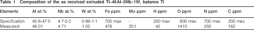
The material was produced as a vacuum arc melted ingot, which was then canned and hot extruded by Plansee (Tyrol, Austria) at an extrusion ratio of 14∶1 and the microstructure suggests an extrusion temperature high in the α+γ, or low in the α phase fields. While the material was nominally Ti–46–5–1 the analysed composition is shown in Table 1. Relatively high levels of oxygen and nitrogen should be noted. Some of this material was taken and heat treated at 1170°C for 48 h (air cooled) to produce a duplex microstructure. All of the mechanical testpieces were taken parallel with the extrusion direction.
Composition of the as received extruded Ti–46Al–5Nb–1W, balance Ti
Tensile testpieces were machined from cylindrical blanks of 10 mm diameter and 70 mm length, which had been wire eroded from the periphery of the extruded bars, both under the heat treated and as extruded conditions. The round bar tensile testpieces had the gauge length ground and the parallel section of the gauge length was 23 mm, with a diameter of 3·99 mm. It should be noted that it was necessary to increase the radius between the testpiece shoulders and gauge length, compared with standard tensile testpiece geometries. This was to ensure that premature fracture at the stress concentration, which is present in most testpiece designs at the transition from the gauge length to the shoulders, did not occur. Tensile testing was undertaken at room temperature, 300, 500, 700, 750 and 850°C (in laboratory air). A strain rate of ∼1×10⁻⁴ s−1 was used for the room temperature tensile testing up to failure and the plastic elongation was determined from the extensometry measurements. The extensometer gauge length was 10 mm. The same strain rate was used for the elevated temperature testing up to the 0·5 proof stress, with a constant crosshead speed then applied to give a comparable nominal strain rate up to fracture.
Creep testpieces were also machined from the wire eroded cylindrical blanks taken from the extruded bars, under both the heat treated and as extruded conditions. These testpieces also had the 20 mm gauge length ground and had a diameter of 3·99 mm. Ridges at the ends of the gauge length were used for locating high temperature extensometry. Creep testing was undertaken at temperatures around the expected operating temperature, i.e. 600, 700 and 800°C, and stresses of 100–650 MPa. Metallography of cross-sections through the creep rupture fracture sections was undertaken to investigate the origins of creep fracture. The secondary creep rates from all of the tests were measured and the primary creep strain was defined as the strain to achieve the minimum creep rate.
Testpieces for low cycle fatigue (LCF) testing were also produced, but only under the as extruded condition. These testpieces were of a circular cross-section, with a gauge length of 14 mm and a diameter of 4 mm. Again the gauge length was ground and these testpieces were oriented parallel with the extrusion direction. The testing was undertaken at room temperature and 700°C in laboratory air. Strain controlled fatigue testing was undertaken with a strain ratio (minimum strain/maximum strain) R = 0. A triangular waveform was used with a constant strain rate of 3×10⁻⁴ s−1. The test method conforms to the ASTM standard practice E606 and British Standard BS7270. The stress was continuously monitored and recorded throughout the test.
Results
Microstructure
The microstructure of the as received extruded Ti–46–5–1 alloy is shown in Fig. 1, the region examined corresponds to the middle of the diameter of the extruded bar. Some chemical inhomogeneity can be observed and results in an almost ‘Van Gogh Sky’ type microstructure, more usually associated with the orthorhombic based titanium aluminide alloys,8 but resulting from some level of chemical segregation and relatively high extrusion ratios of ingot material. Chemical analysis by energy dispersive X-ray spectroscopy suggested that the compositional variations were mainly associated with the titanium, aluminium and tungsten levels, with niobium remaining very consistent under all locations. The general microstructure was basically lamellar, with a small amount of a more equiaxed phase, presumably the γ phase, at some of the colony boundaries (Fig. 1). The discrete white phase seen at grain boundaries (labelled GBP in Fig. 1) was found to be rich in both niobium and tungsten. Tungsten macrosegregation in the ingot metallurgy material has been reported in the literature,9 and this may be a manifestation of the effect.
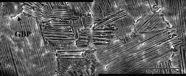
Microstructure of as extruded Ti–46–5–1 alloy, showing colony size: chemical composition of grain boundary particle (GBP) is 54·4Ti–33·0Al–7·3Nb–5·2W (at-)
The lamellar colony size in the Ti–46–5–1 was ∼75 μm and inspection at higher magnifications showed that the lamellar width spacing was about 0·4–0·5 μm (Fig. 2). These microstructures were found throughout the extruded bar, both at other radial positions and also at different positions along its length. This suggests good microstructural homogeneity in this material.
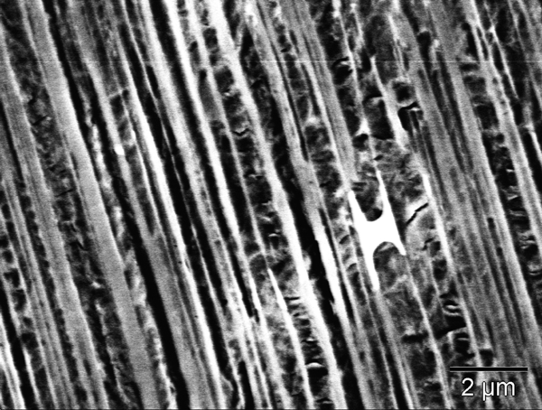
Lamellar width of as received Ti–46–5–1: backscattered electron image
The microstructure obtained after heat treatment for 48 h at 1170°C may be seen in Fig. 3. This shows significant coarsening of the lamellar structure and more blocky γ phase. The tungsten and niobium rich grain boundary particles were retained.
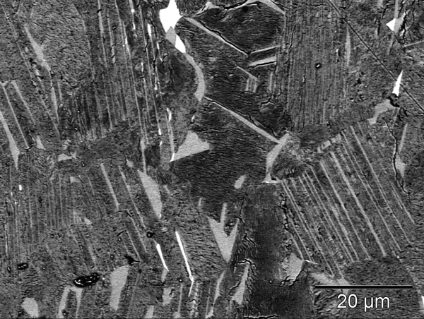
Near duplex microstructure seen after heat treatment at 1170°C for 48 h (air cool): backscattered electron image
Tensile properties
The tensile properties of the as extruded Ti–46–5–1 alloy are shown in Fig. 4. These show an average 0·2 proof strength of 820 MPa, with a tensile strength of 950 MPa and an elongation of 1·0 at room temperature. These values were obtained from six tests and show encouragingly low levels of scatter. When the effects of temperature are considered, there is only a relatively small decrease in the tensile strength from room temperature to ∼880 MPa at 700°C. However, by 850°C the tensile strength had reduced to ∼670 MPa. The elongation to failure increased to ∼5 at 700°C, from ∼1 at room temperature, while at 850°C the ductility had increased to almost 18. This suggests that the ductile brittle transition temperature for this material is ∼700°C.
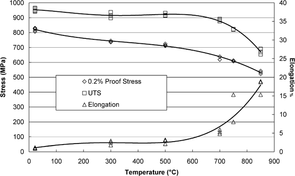
Effect of temperature on tensile properties of as extruded (fully lamellar) Ti–46–5–1
A similar plot of the tensile properties for the duplex material is shown in Fig. 5 and here the significant reduction in strength may be seen, with room temperature proof and ultimate strengths of ∼650 and ∼780 MPa respectively. These strengths did not fall rapidly above 750°C, compared with the as extruded material. However, there was a significant increase in the ductility at 850°C for the duplex material.
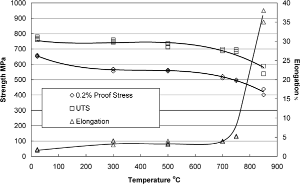
Effect of temperature on tensile properties of heat treated Ti–46–5–1: 1170°C, 48 h, air cool – near duplex
Creep properties
Creep curves for the extruded material are shown in Fig. 6. The curve at 700°C was typical for material tested at this temperature or 800°C, showing a conventional primary, secondary and tertiary behaviour. However, at 600°C it was found that very low creep ductilities were found and no tertiary deformation observed. This corresponds with the ductile–brittle transition observed with the tensile tests above. Sections through the fracture location at both 800 and 600°C are shown in Figs. 7 and 8 respectively. Here the significant cavitation that has occurred after testing at 800°C, mainly perpendicular to the stress axis, may be readily seen (Fig. 7). This cavitation was concentrated at colony boundaries and extended a significant distance (∼2 mm) from the fracture site. Very similar structures were observed after testing at 700°C. In contrast, at 600°C little or no cavitation was observed (Fig. 8), although cracking along lamellae and at colony boundaries was found. All of the damage seen was concentrated at the fracture location.
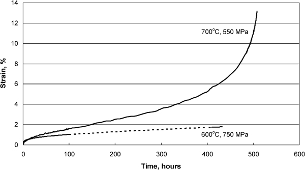
Typical creep strain curves to failure for lamellar Ti–46–5–1, tested at both 600 and 700°C in air
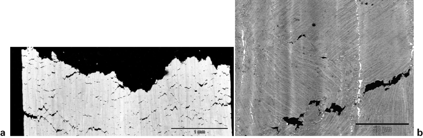
Sections through the fracture surface of a creep tested sample showing extensive cavitation: a macroscopic view; b decohesion at lamellar boundaries
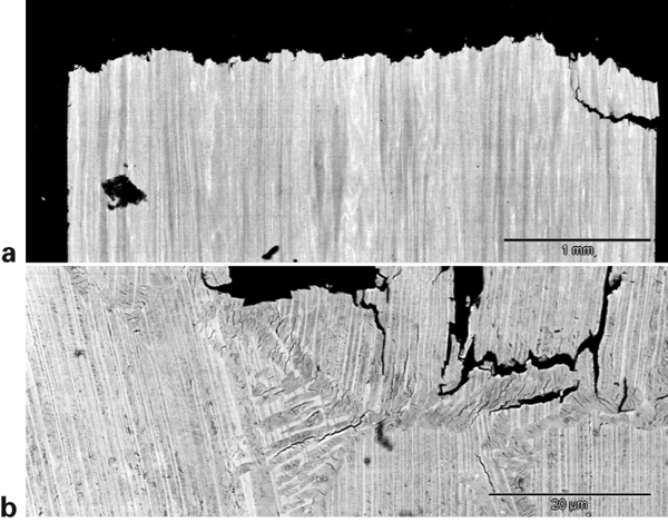
Image from section through fracture surface of sample creep tested at 750 MPa and 600°C
A limited amount of creep evaluation of the duplex material was undertaken and an example of the data obtained at 700°C and compared with the as extruded material may be seen in Fig. 9. It is clear that the secondary creep rates for the duplex material were somewhat higher than those for the as extruded condition. It is also worth noting that in the duplicated tests shown in Fig. 9, the creep performance was reasonably reproducible.
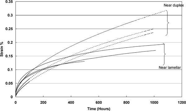
Comparison of creep deformation of duplex (dotted) and as extruded (solid line) Ti–46–5–1 at 700°C and 200 MPa
Fatigue properties
The strain controlled (R = 0) fatigue lives of the lamellar Ti–46–5–1 at room temperature and at 700°C are shown in Fig. 10. The flat curves, typical of relatively brittle material can be seen, even at 700°C. There was a significant reduction in fatigue performance at 700°C, compared with room temperature, which is perhaps somewhat surprising given the significantly improved ductility at 700°C. Fractography showed that some of the room temperature tests failed from a subsurface initiation site: a facetted structure approximately perpendicular to the applied stress. The size of the facetted structure was ∼100 μm, corresponding approximately with the colony size in this material and the fracture appeared to be along lamellae.
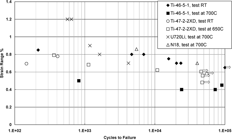
Strain controlled LCF (R = 0) performance of Ti–46–5–1 at room temperature and 700°C, along with some other comparative materials
Discussion
The extruded Ti–46–5–1 alloy evaluated here has demonstrated good microstructural homogeneity and mechanical performance from room temperature up to 700°C. The tensile and creep performance of this material was reduced following heat treatment to generate a duplex microstructure, rather than the near fully lamellar structure in the as extruded state. This suggests that the near lamellar microstructure generated during extrusion may be the preferred structure for service; however, it is not clear whether this is sufficiently reproducible from batch to batch on an industrial scale to be acceptable to designers.
The as extruded (lamellar) Ti–46–5–1 tested here displays some of the highest tensile strengths measured for a γ-TiAl alloy,1,4,5,7 although the Ti–44–46Al–5–10Nb+B+C alloys family of alloys have shown higher values of tensile strength of up to 1085 MPa, with a room temperature ductility of 2·5.2 The high strength of the extruded Ti–46–5–1, compared with other product forms of similar alloy compositions,6,7 was thought to be associated with the refined microstructure seen after extrusion. Compared with other compositions, the high strength of the Ti–46–5–1 may be associated with the tungsten, refining the lamellar width9 and providing solid solution strengthening, and the high oxygen and nitrogen content.10 The reduced strengths measured for the duplex microstructure are thought to be associated with the increased lamellar width and the presence of more blocky γ grains.
In addition to the high tensile properties, excellent creep performance was also found for the extruded Ti–46–5–1. A rupture life plot of the Ti–46–5–1 (lamellar microstructure) creep performance with a first generation γ-TiAl alloy is shown in Fig. 11. This shows that the overall creep performance of the Ti–46–5–1 alloy surpassed the Ti–47–2–2XD alloy,11 giving an almost 100°C advantage, and was also superior to the Ti–47Al–2W alloy (ABB-23)5 which was specifically designed for high creep performance (not shown). The γ-TiAl alloys in this comparison are shown in the fully (or near) lamellar structural condition, which is expected to provide the best creep performance. Again the benefit of the refined lamellar microstructure provided by extrusion is thought to be a major factor in the difference in performance, despite the smaller grain size after extrusion. This benefit may be associated with a proposal for similar alloys that a dislocation glide mechanism during creep deformation may operate12 and thus short, fine lamellae may impede this glide.
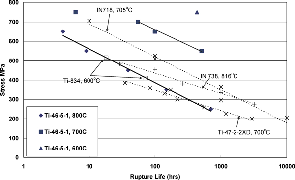
Comparison of creep performance of extruded Ti–46–5–1 (lamellar microstructure) with alternative γ-TiAl and titanium alloys and selected Ni alloys
A couple of well known nickel alloys have also been included on the rupture life plot (Fig. 11) to provide a baseline of conventional alloys. The Ti–46–5–1 was found to exhibit a significantly better creep performance than the wrought nickel alloy, IN718.13 However, the more advanced wrought nickel alloys, such as U720Li, offer a creep performance similar or superior to this Ti–46–5–1 alloy.14 The conventionally cast nickel IN738 alloy13 offers better creep performance than the Ti–46–5–1. Clearly this plot shows absolute values and no density correction has been attempted, but where component mass is important, then once the density differences are also considered, the Ti–46–5–1 becomes competitive even with the cast nickel alloys.
The creep behaviour has been examined in more detail, considering both the primary strain regime and the secondary creep region.
The primary strain behaviour of the γ-TiAl alloys is very important, since the time to achieve some small strain (e.g. 0·5) is often taken as the design life for a component, because of constraints, such as the need for turbine blade tips to avoid rubbing on casings. The primary strain behaviour of the Ti–46–5–1 is shown in Fig. 12. It is worth noting that since the primary strain only contributes ∼3 (for all but the rupture test at 600°C) to the overall creep rupture life, this is presumably not a major factor in the good rupture life performance of these alloys noted on Fig. 11.
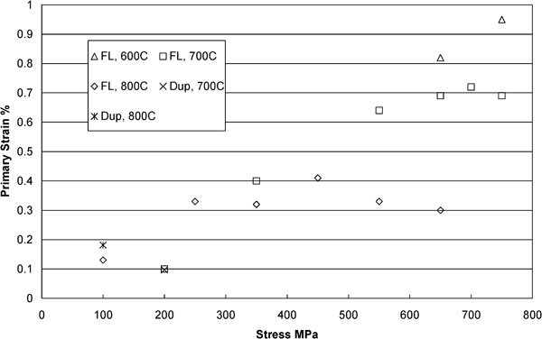
Effect of temperature and stress on primary creep strain of lamellar Ti–46–5–1
The magnitude of the primary strains measured in this work compared well with those reported in a literature review of this subject.15 The increase in the primary strain with stress was similar to that shown in the literature review.15 This report suggested that there was a threshold stress below which a reasonably constant and small primary strain was seen (typically up to 0·2).15 This threshold was thought to be associated with phenomena such as twinning, or stress induced phase transformation.15 However, in this current study (Fig. 12) there was only very limited evidence for this threshold stress effect and this is consistent with the lack of twining or phase transformations observed microstructurally.
At the highest creep stresses evaluated, the primary strain of the extruded Ti–46–5–1 (near lamellar condition) became relatively constant, above a threshold stress (Fig. 12). The level of this upper constant primary strain behaviour was found to vary with test temperatures, with this maxima reducing with increasing temperatures. It was also noted that the time to reach this upper threshold primary strain decreased with increasing temperatures. Such behaviour appears to be consistent with thermally mediated relaxation of the high dislocation densities reported in these materials and associated with primary creep deformation.16
In the secondary creep regime the minimum creep rate of the extruded Ti–46–5–1 was very attractive, compared with other alloys (Fig. 13). Even when compared with the third generation high niobium and particle strengthened alloys (also under the lamellar microstructural condition), for example the wrought alloy Ti–46Al–5Nb–0·2C–0·2B alloy (known as γ-Met PX), the minimum creep rate of the Ti–46–5–1 was similar.17 The minimum creep rate of the Ti–46Al–5Nb–0·2C–0·2B alloy under an equiaxed microstructural condition17 was significantly higher than that of the Ti–46–5–1 under the near lamellar condition. Thus the benefit of the particulate boride and carbide strengthening is not entirely clear on virgin material but is probably more significant for the long term thermal stability of the microstructures and the creep performance.
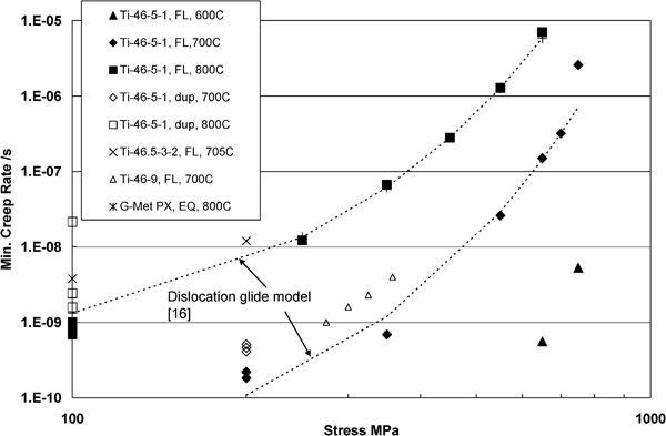
Comparison of minimum creep rate for Ti–46–5–1 at various temperatures and with varying alloys
Figure 13 shows that the power law creep mechanisms are not applicable to the Ti–46–5–1 material in the secondary creep regime and this is consistent with observations in the literature.12 However, a hyperbolic sine based representation of the minimum creep rate behaviour appears to track the data points reasonably well (Fig. 13). This formulation was based on a dislocation glide mechanism by a number of authors18,19 and can be written as

where K0 is the constant (related to grain size), QL is the activation energy, R is the universal gas constant, T is the absolute temperature, σ is the applied stress and σ0 is the stress constant (related to back stress or internal stress).
Curve fitting of this equation to the data available here suggests an activation energy of 366 kJ mol−1 for this material at both 700 and 800°C. This is similar to that reported for a range of γ-TiAl alloys12 and appears to be an average of a number of potential mechanisms. The stress constant σ0 obtained by fitting the data here was between 62 and 65 MPa and this is again similar to that reported for a γ-TiAl alloy with a fine lamellar spacing. This is consistent with the Ti–46–5–1 alloy here and its refined microstructure, supporting the benefit of the refined microstructure on the secondary creep performance of the alloy.
Comparison of the secondary creep rates for the two microstructures investigated in this study, showed that the duplex microstructures exhibit about a two-fold increase in the strain rate, compared with the lamellar structure under the same conditions. This is consistent with previous studies of the microstructural effects on creep rate.12
The creep elongation to failure of the extruded Ti–46–5–1 was relatively low at 700–800°C compared with alloys such as Ti–47Al–2Nb–2MnXD and Ti–48Al–2Nb–2Mn,1 but despite this, the creep ductility of the Ti–46–5–1 was generally in excess of 10 and thus reasonably similar to conventional metallic materials. The exception to this was at 600°C where a ductility of 2·6 was found and this demonstrates that the effect of the ductile–brittle transition occurs under creep as well as the more usual tensile conditions. Below the ductile/brittle transition the shape of the creep curve was found to consist only of the primary and secondary behaviour, with no tertiary creep being observed. When the Ti–46–5–1 alloy was tested at 800°C the ductility was reduced, but this is thought to be associated with the oxidation that takes place at this temperature. This is supported by the metallographic sections through the fractured testpieces (Fig. 14) which show the surface oxidation. Further examination showed that the damage within the microstructure occurred at colony boundaries or other microstructural inhomogeneities and this is consistent with previous observations of crept Ti–47Al–2Nb–2MnXD and Ti–48Al–2Nb–2Mn.11
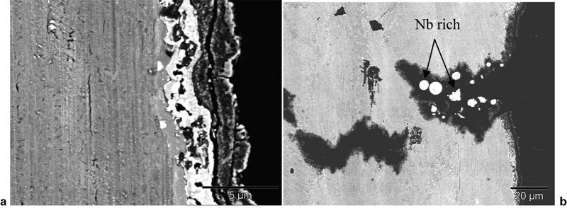
Cross-sections through surface creep testpiece tested at 800°C, with 250 MPa load, a oxide scale formed and b niobium rich particles within surface breaking crack (both backscattered electron images)
It is worth noting that the rupture life and secondary creep data generated here follow a Monkman–Grant type of relationship,20 as shown in Fig. 15. This relationship permits the final life of the material under some arbitrary conditions to be estimated from the secondary creep rate, which can be significantly easier to measure than the final rupture life (although more rupture data at the lowest stresses are needed to validate the model). An exception to the Ti–46–5–1 following this relationship was for the material tested at 600°C, which was found to fall significantly below the remaining curve. This is presumably associated with the low creep strain to failure that was found at this temperature.
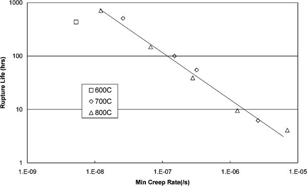
Monkman–Grant plot of Ti–46–5–1 alloy
The final property to be examined is the LCF performance and there was a clear reduction in life at 700°C, compared with room temperature, for a given strain range. This is perhaps surprising, given the increased ductility at 700°C and the reduction may be associated with oxidation effects21 over prolonged periods.
In comparison with other materials at ∼700°C, the fatigue performance of the Ti–46–5–1 alloy appears to be less impressive. Thus the Ti–47–2–2XD alloy, tested at 650°C but otherwise the same cycle, offered higher fatigue lives than the Ti–46–5–1, although this may be associated with the 50°C temperature difference. The performance of one well known wrought nickel alloy, Udimet 720Li14 and a second somewhat newer French alloy, N18, has been added to the strain range–failure cycles plot (Fig. 10).22 These two wrought nickel alloys (Udimet 720Li and N18) showed significantly better fatigue lives than either of the two γ-TiAl alloys. This indicates the superiority of the nickel alloys in components that experience localised strain (e.g. bolt holes on turbine discs), although weight considerations may also be important.
The cyclic deformation behaviour of the Ti–46–5–1 is shown in Figs. 16 and 17 and it can be seen that at room temperature there was some evidence for cyclic softening towards the end of life (Fig. 16). This finding is in contrast to work on Ti–48Al–2Cr–2Nb, also at room temperature and R = 0,23 where some cyclic hardening was seen. At the elevated temperature very little change in the peak cyclic stresses was seen for the Ti–46–5–1, throughout the test life (Fig. 17) and this is consistent with that reported elsewhere for the elevated temperature behaviour of Ti–48Al–2Cr–2Nb alloy23 and XD-45.24 Thus it would appear that the deformation behaviour at elevated temperature between the two alloys was similar, while at room temperature differing deformation mechanisms appeared to be active in the two materials.
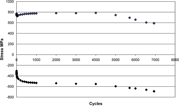
Maximum and minimum stress variation with life for room temperature LCF test of Ti–6–5–1, R = 0 and maximum strain is 0·8
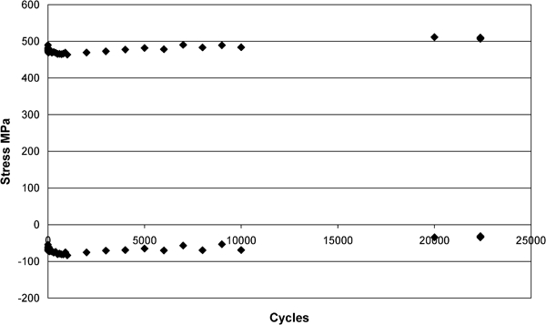
Maximum and minimum stress variation with life for 700°C LCF test of Ti–46–5–1, R = 0 and maximum strain is 0·4
Conclusions
The tensile and creep performance of the as extruded, fully lamellar Ti–46–5–1 alloy were found to be excellent, with some of the highest recorded strengths and the best creep performance in a comparison with other γ-TiAl alloys. The tensile ductility was ∼1 and well within accepted values for γ-TiAl alloys. This ductility increased to ∼10 at 700°C, with the ductile–brittle transition occurring between 500 and 700°C.
Assessment of the creep rupture performance of the Ti–46–5–1 showed that this alloy was significantly superior to other γ-TiAl alloys and indeed was approaching some of the creep resistant nickel alloys, such as cast IN738. If the density differences between the γ-TiAl alloy and the nickel alloys are accounted for, then the properties of Ti–46–5–1 become even more attractive. The primary creep strains of the Ti–46–5–1 were ∼0·1 at low stresses but increased to a plateau with increasing stresses.
This alloy has demonstrated excellent tensile and creep properties in the as extruded state. To benefit from these properties, very close control over the extrusion process will be necessary to maintain consistency in the resultant mechanical performance of the material. If this process control can be demonstrated, then this extruded alloy offers a good basis for subsequent manufacturing processes.
However, the LCF performance of the material was found to be significantly poorer than that for more conventional wrought nickel alloys, and this feature must be noted when selecting applications for this material.
Footnotes
Acknowledgements
The authors would like to thank UK Ministry of Defence Applied Research Programme and the Department of Trade and Industry Aerospace Research Programme for funding this work and Mr R. Savage, Mr M. Squibb and Mr M. Sumner for assistance with the tensile and creep testing. In addition, thanks are due to Plansee (Tyrol, Austria) and Rolls-Royce (London, UK) for the supply of the material.