
Abstract
Microstructural phase transformations, commonly named white layer on hard turned components, are becoming one of the most interesting research subjects for the scientific community. Three main theories have been proposed to justify the mechanisms of white layer formation: rapid heating and quenching, which results in sudden microstructural phase transformation; severe plastic deformation, which produces a homogenous structure and/or a very fine grain size microstructure; and surface reaction with the environment. The present work aims to understand which of the above mentioned mechanisms is the main cause of the white layer formation when AISI 52100 hardened steel is machined by cubic boron nitride inserts. For this reason, an experimental campaign was carried out, and several experimental techniques were used in order to analyse the machined surface. In particular, optical and scanning electron microscope were utilised for surface topography characterisation, while microstructural phase composition and chemical characterisation have been performed by means of X-ray diffraction and energy dispersive spectroscopy techniques. The experimental results prove that the white layer is the result of microstructural alteration, i.e. the generation of a martensitic structure.
Introduction
During the last decade, machining of certain materials in the hardened state offered the possibility to eliminate the extra processing steps, such as finish machining, heat treatment and grinding, 1 1,2 improving, in this way, the productivity of the process and the life of the component. Several studies 3 3,4 have shown that the relatively more aggressive grinding process parameters, employed under typical production conditions, could reduce the life of the final part under service conditions. In fact, they result to have deleterious effects on the surface integrity of hardened components, where failure usually occurs through fatigue, wear, corrosion, etc. Thus, compared with grinding, hard turning could be considered economically competitive in making a variety of precision components, with substantial potential benefits. However, hard turning applications can also generate detrimental process induced phenomena, such the white layer formation on the machined surface, which is often detrimental to component life.5 In fact, it has a significant impact on the magnitude of the maximum residual stress and on the location of its compressive peak. 6 6,7 This layer is typically a few tens of micrometres thick, hard and brittle, and presents a relative resistance to etching and, consequently, a white appearance when observed by an optical microscope.
Whereas several studies were conducted on white layer analysis during the machining of hardened steels,5,7–11 only a few were carried out in order to investigate the mechanisms related to white layer formation.12–15
According to Griffiths,16 three main general mechanisms are the possible causes of this microstructural alteration:
the plastic flow that produces a homogeneous structure or one with a very fine grain structure
a rapid heating and quenching resulting in transformation products
a surface reaction with the environment, such as nitriding or oxide.
Therefore, the objective of the present paper is to figure out which of the above mentioned theories is the main cause of while layer formation when AISI 52100 hardened steel is machined by cubic boron nitride (CBN) inserts. For this reason, an experimental campaign was carried out, and several experimental techniques were used in order to analyse the machined surface. In particular, optical and scanning electron microscope (SEM) were utilised for surface topography characterisation, while X-ray diffraction (XRD) and energy dispersive X-ray spectroscopy (EDS) techniques were respectively used for microstructural phase composition and chemical characterisation. The experimental results prove that the white layer observed on the machined surface of the hard turned specimens is the result of microstructural alteration, i.e. the generation of a martensitic structure.
Prior investigations on white layer formation
The concept of ‘white layer’, which is also called ‘phase transformed materials’, ‘white phase’, ‘non-etching layers’, ‘white etching’, etc., is not new, and it refers to hard surface layers appearing white under the microscope and formed in a variety of ferrous materials under many different conditions. However, ‘white layer’ is just a description of the structure's appearance in micrographs but not a sufficient characterisation. Generally, white layers can be divided into two groups with respect to their etching behaviour. Belonging to the first group are white layers that remain white even after applying special etching chemicals or increased etching times. White layers on electrodischarge machined surfaces or in high loaded ball bearing races often belong to the first group. On the contrary, the white layers of the second group contain fine grained martensitic structures, which may arise in short time heat treatment operations. Both typologies are characterised by high brittleness and susceptibility to cracking and hence regarded as a damage of the component. In some cases, also austenitic layers were detected. As shown by Barry and Byrne12 and Chou and Evans,13the high content of austenite on the white layer surface is a clear indication of how, during the machining process, the martensitic transformation takes place. It results in a higher hardness compared with that measured on the bulk and also an apparently featureless structure when viewed under low powered microscopes. The first approach to the study of the possible causes of the white layer was carried out in 191217when, analysing the surfaces of used steel wire ropes, the formation of white etching layers was observed. After that, many researches found the occurrence of such kind of phenomenon in different areas: at the surface of many engineering components (such as pistons, rail heads, roller bearings, etc.) removed from their service environment and also on the surface of manufactured components, such as ground, drilled or turned pieces. Many efforts have been performed in order to understand the mechanics of white layer formation, and there is a general agreement on stating that different types and forms of white layer have been observed, depending upon the precise operating conditions and the materials used.
Anyway, three main contributory mechanisms have been identified as responsible for white layer generation:16
the mechanism of surface reaction with the environment
the mechanism of severe deformation that produces a homogeneous structure or one with a very fine grain structure
the mechanism of rapid heating and quenching, which results in transformation products.
The hypothesis of surface reaction with the environment was elaborated after finding white layer on the worn surface. In such a case, in fact, particular environments, such as oxygen and nitrogen, have been identified. Although it is difficult to understand how atmospheric reaction can contribute to subsurface white layer formation, several mechanisms of surface reaction have been suggested to prove it.18 Sometimes, it was hypothesised that both very large strain deformation19(shear strain >2–3) and strain rates are the principal factors contributing to the formation of this layer with ultrafine grained or nanocrystalline structures.20 Therefore, the mechanical effect has been explored as the possible dominant factor for white layer genesis. Mybokwere et al.,21 Cho et al.22 and Zhang et al.23 show that dynamic recovery is the dominant process in the formation of surface white layers and internal white adiabatic shear bands, which are internal non-etching white bands in steels, deformed at high strain rates (from 103 to 106 s−1). Furthermore, in machining, most of the white layers are generated when the cutting conditions are heavy as well as when worn tools are used.20
Finally, concerning the third possible mechanism of white layer formation, it is well known that temperatures in machining operations can reach high values, so it is likely that at the interface between the tool and the workpiece, temperatures are sufficient to cause microstructure modifications or austenitisation in the case of ferrous alloys. In particular, as far as steels are concerned, Ramesh14 found that the influence of stress and strain on the austenite start temperature, due to the high dislocation density associated with large strain, produces an approximate austenite start temperature of 550–650°C. Moreover, Barry and Byrne12 and Chou and Evans13affirmed that the high austenite content of the surface white layer clearly confirms the occurrence of the reverse martensite transformation during machining. Such metallurgical change is due to the rapid increase in temperature, combined with high pressure generated by the action of the tool, transforming the machined surface to the austenitic state. When the tool leaves, the surface cools down, and the critical speed of martensite formation is reached by convection of heat into the air and by conduction into the workpiece material. As a result of the high speed (Chou and Evans13have estimated the surface cooling rate in hard turning to be on the order of 104°C s−1), some austenites have no time to transform, and some retained austenite traces can be found in the surface layer.
Thus, machined surfaces have been the subject of a number of studies; some of them are briefly reported. Many experiments have also been carried out in order to identify the possible predominant cause of white layer formation providing, often, conflicting results.
Guo and Sahni24 made a comparison between turning and grinding of AISI 52100 steel (62–63 HRC). Considering that grinding is a process with a tool–workpiece contact area greater than turning, it causes higher surface temperatures, high heat penetration within the component and lower average mean contact stresses.
After the comparison of the two processes, the authors24 came to the conclusion that, in grinding, the white layer has greater thickness than turning. Additionally, it was proved that the surface hardness of the ground component was 40 greater than the one obtained by turning; this increase was generated by thermal and mechanical effects connected to the differences of the two processes. In contrast, nothing was reported concerning the mechanisms related to its formation.
Brinksmeir and Brockhoff25 showed that, due to a critical rate of heating and quenching (as in turning), structures with very fine grains can be formed, especially in martensitic steels. In addition, they noticed that the white layer thickness arose when the temperatures involved were above the austenitising temperature of the considered steel.
Barbacki and Kawalec26 studied the formation mechanism of both white and dark layers during the turning process. Their results highlighted that the formation of dark layers in the high speed turning of steel alloys was hindered by their high tempering temperature.
Österle et al.27analysed the white layer generated in pearlitic steels, which are used for the construction of railway tracks, using transmission electron microscopy and XRD techniques. Their studies demonstrated that the formation of white layer was due to the two concurrent effects: the mechanical, due to the presence of drastic plastic deformations, and the thermal, tied to the rapid heating followed by quenching.
Ramesh et al.28performed tests on hard turning AISI 4340 and 52100 (57 HRC) steel alloys and observed the clear formation of white layer and the absence of dark layer in alloy 4340; this lack was attributed to the fact that the tempering temperature would have never been reached in the underlying layers.
Experimental set-up and operating parameters
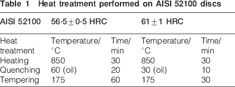
In order to perform orthogonal cutting conditions on the samples, discs of hardened AISI 52100 steel (outer diameter = 150 mm; thickness = 2·5 mm) were prepared by sawing from a round bar stock, followed by machining, heat treatment and gentle grinding to restore flatness and parallelism resulting from the distortion during quenching. The discs were then divided into two lots and differently quenched and tempered to harden the discs to different initial hardness levels: 56·5±0·5 and 61±1 HRC respectively (Table 1).
Heat treatment performed on AISI 52100 discs
Dry orthogonal cutting tests were conducted on a stiff high speed computer numerically controlled lathe by means of a radial facing operation (Fig. 1). The CBN tool inserts (50 vol.-cBN and TiC binder) had two different edge geometries: chamfered (ISO TNGN 110308S) and honed (ISO TNGN 110308E). They were mounted on a CTFNR3225P11 tool holder with a rake angle of −8°, which was held in a Kistler 9121 three-component piezoelectric dynamometer for measuring forces.
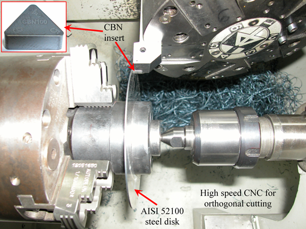
Experimental set-up for orthogonal cutting tests
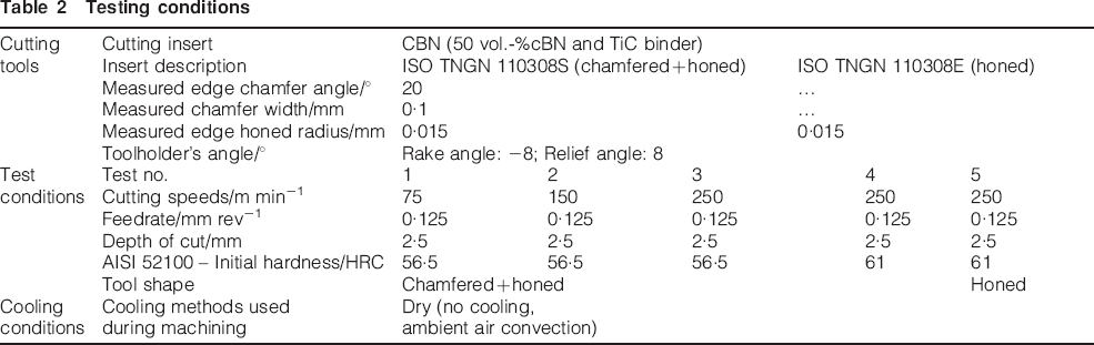
The discs were machined by varying the cutting speed, initial workpiece hardness and tool shape, as indicated in Table 2. Moreover, three repetitions for each test were executed. The cutting time of each test was accordingly set in order to reach a final diameter of 80 mm. It is important to underline that, in such conditions, a flank wear of 0·1–0·15 mm was revealed on the utilised tools.
Testing conditions
In order to perform microhardness characterisation, samples of 5×5 mm were sectioned by wire electric discharge machining from each disc after machining. Successively, the samples were mounted in a hard resin to ensure edge retention and then were ground and polished. Microhardness was measured on the machined surface using a microindentation Vickers hardness tester with a certificated diamond indenter The applied load and the indentation time were 100 g and 10 s respectively. Five measurements were made on the machined surface, with the measurement locations well spaced laterally to avoid interference between indentations.
Concerning the microanalytical techniques used, the sectioned and polished samples were etched for ∼3 s using 5 nital solution to observe white and dark layers using an optical microscope (500×) and SEM. An EDS has also been performed in order to obtain a qualitative and quantitative elemental analysis of the machined surface. Finally, an XRD test gave information about microstructural phase composition of the machined material. It was conducted using a X-ray equipment X-D8 Discover Bruker axs with Cu radiation (λ = 1·54 Å, E = 8 keV). The samples were accordingly positioned at the centre of the plate into the X-ray goniometric in order to ensure a correct beam irradiation. Furthermore, several configurations were selected (i.e. symmetric, asymmetric and Bragg Brentano) in order to maximise the surface reflected signal. Finally, scan precision was 0·01°, while the acquisition time was accordingly varied.
Results and discussion
Cutting forces and surface hardness modification
Figure 2 shows the trend of the average cutting forces for each experiment calculated when mechanical and thermal steady state conditions were reached (a cutting time of 10–15 s was enough to achieve steady state condition), while the error bars represent the standard deviations of the signal. It is possible to note that both the principal cutting force Fz and the tangential force Ft decrease by increasing the cutting speed when a chamfered tool is used.
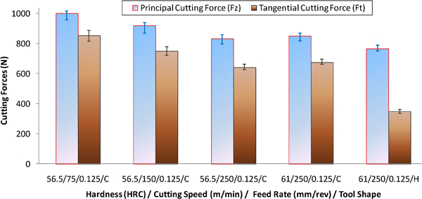
Experimental cutting forces (Fz: principal cutting force; Ft: tangential cutting force) at varying cutting speed, initial material hardness and tool shape (C: chamfer, H: hone)
Figure 2 also evidences as both principal and tangential cutting forces slightly increase with increasing initial hardness. These observations highlight that the influence of the cutting speed is stronger than the hardness on the cutting force trends. Finally, the cutting forces decrease when honed tool preparation was utilised.
Figure 3 illustrates the initial hardness variation in the machined samples. In particular, the results highlight that, in all of the investigated cases, the surface hardness is higher than that of the bulk material, validating the theory of the microstructural alteration on the surface. Furthermore, the value of the ratio HV0·1max/HV0·1 initial increase with increasing cutting speed, while it decreases when higher initial workpiece hardness as well as honed tool preparation were selected. These experimental observations are in agreement with those previously found by Poulachon et al.20
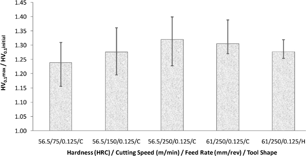
Experimental hardness modification at varying cutting speed, initial material hardness and tool shape (C: chamfer; H: hone)
However, it is worth to point out that the observed hardness modification can be attributed to either rapid heating or quenching, which results in microstructural transformation as well as severe plastic deformation and consequently grain size refinement.
White layer surface analysis by means of optical microscope and SEM
Figure 4 shows the typical surface structures with the etched white layer in evidence observed by an optical microscope.
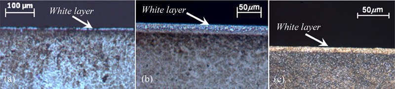
Surface structures of hard machined samples observed by optical microscope
Figure 5 reports the measured white layer thickness at varying cutting conditions, initial workpiece hardness and tool shape. The experimental results highlight the different thicknesses (ranging from 5 to 15 μm) of the white layer at varying cutting parameters (cutting speed and initial hardness) and tool shape. In particular, as shown in Fig. 5, the white layer increases when the cutting parameters are more severe and also when the initial hardness is higher. In contrast, a shallow white layer is found when the honed tool preparation was used.
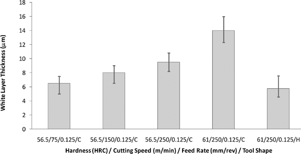
Experimental white layer thickness at varying cutting speed, initial material hardness and tool shape (C: chamfer; H: hone)
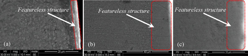
Images (SEM) of hard machined samples
In addition, SEM analysis on the machined surface demonstrates an alteration of the microstructure (Fig. 6). In particular, the SEM images highlight a featureless structure since the turned white layer is usually etch resistant. Consequently, both optical and SEM images permit to assess that the microstructural alteration is a consequence of a synergic thermal and mechanical effect that also causes grain refinement and creates a homogeneous structure that appears featureless on the SEM images.
However, it is important to underline that surface analysis is not enough to better highlight which of these two mechanisms is predominant on white layer formation; thus, deeper microsurface investigations, such as EDS analysis or XRD phase analysis, are needed.
Energy dispersive spectroscopy analysis
Figure 7 depicts the observations acquired by EDS analysis. As can be noted, a higher carbon content on the machined surface than that observed on the bulk material was found due to the presence of retained austenite within the white layer. A high carbon content was also detected on the other machined surfaces obtained at varying cutting conditions, tool shape and initial hardness. It is important to underline that similar observations were also found by Zurecki et al.29 and Ramesh.14
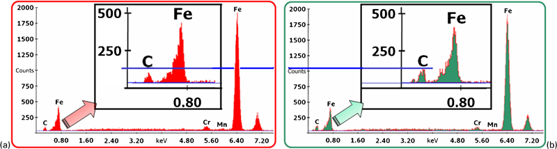
Energy dispersive spectroscopy analysis on test 1
X-ray phase analysis
Figure 8 shows the phase analysis obtained by means of XRD technique on samples before the machining operation and, therefore, without the presence of white layer on the investigated surface. In particular, X-ray phase analysis on the unmachined surface evidences two peaks at 44·6 and 82·3° that, according to Bragg's law and the data reported in the materials handbook,30 correspond to ferrite-α respectively at (110) and (211) Miller's indices.
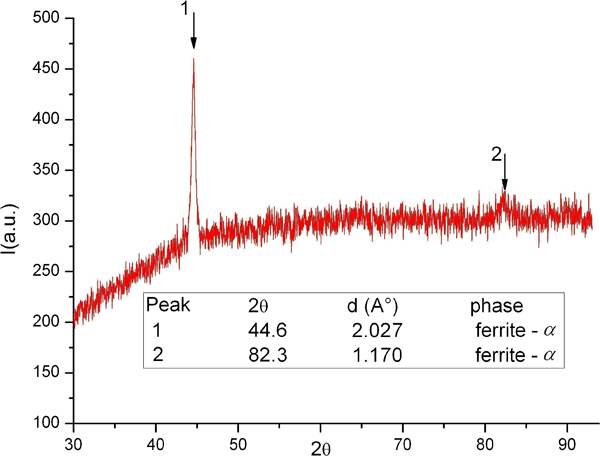
X-ray phase analysis on specimen before machining operation
In contrast, when samples with the presence of white layer on the machined surface were investigated, the X-ray phase analysis shows several peaks (Fig. 9). Once again, two peaks are located at 44·6 and 82·3°, which correspond respectively to ferrite-α. What is more, two peaks can be additionally found at 74·68° (peak 3) and ∼43·6° (peak 4). Specifically, peak 3 in Fig. 9 is clearly distinguished and corresponds to retained austenite (220), as reported in the materials handbook31 and found by Bragg's law. On the contrary, concerning peak 4 (Fig. 9), some difficulties in defining the phase were found since two structures can be located here: Fe3C–martensite (102) at 43·5°32 and, once again, retained austenite (220) at 43·7°.31
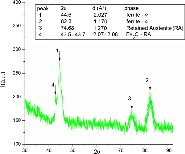
X-ray phase analysis on machined specimen (test 4) with presence of white layer
Therefore, several measurements at varying X-ray geometry configurations (i.e. symmetric, asymmetric and Bragg–Brentano geometries) and for longer acquisition time were carried out on the machined surface in order to clearly detect the peak differences (point 4 in Fig. 9).
Figure 10 reports the phase analysis in the interesting region on both the unmachined specimen and the hard turned surface at varying of X-ray geometry configuration. In particular, X-ray phase analysis on the unmachined surface clearly evidences a peak at 44·6° (110 ferrite-α) with a magnitude of 0·28 at half height (Fig. 10a). In contrast, the X-ray phase analysis on the hard turned surface still shows a peak at 44·6° (110 ferrite-α), but the magnitude at half height is about twice (0·52 instead of 0·28) than the previous one either in symmetric geometry configuration (Fig. 10b) as well as in Bragg–Brentano (Fig. 10c) and in asymmetric geometry configurations (Fig. 10d).
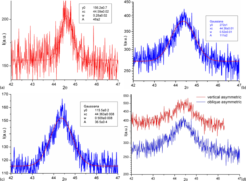
Phase analysis (XRD) on unmachined specimen a obtained by symmetric geometry configuration and XRD phase analysis on hard turned specimens (test 4) with presence of white layer using b symmetric, c Bragg–Brentano and d asymmetric geometry configurations
Although the reason for the above mentioned twice peak magnitudes can be attributed to the presence of peaks related to both retained austenite (111) and Fe3C–martensite (102) hidden into the ferrite-α (110) peak, unfortunately, due to the poor roughness of the machined surface, it was not possible to reduce the signal noise. Moreover, it was also tried to increase the acquisition time in order to better emphasise the two peaks, but for longer acquisition times, the iron absorption threshold was close to the beam incident Cu radiation (8 keV), causing signal noise.
Therefore, a numerical method was applied in order to separate the two peaks. In particular, as illustrated in Fig. 11, both ferrite-α and Fe3C–martensite/retained austenite peaks were rebuilt at 44·6 and 43·6° respectively by imposing an equal magnitude.
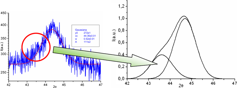
Simulation of α-ferrite peak with presence of left side threshold due to retained austenite and Fe3C–martensitic peaks
In such a case, the numerical peak presents a shoulder on the left side, which produces slightly decentralisation and a twice magnitude of the ferrite-α peak. It is important to underline that this numerical result is coherent with other experimental XRD observations, 18 29 18,29,33which clearly show a left side threshold for ferrite-α peak in the presence of retained austenite and Fe3C–martensite. Of course, the occurrence of the latter microstructure appears when a martensitic structure is generated.
Conclusions
In the present paper, an experimental analysis of the white layer formation in AISI 52100 turned pieces has been carried out. The experimental results highlight that the machined surface was subject to microstructural alteration with consequent formation of the white layer. Furthermore, the thickness of the altered region depends on the cutting parameters, initial hardness and shape of the cutting tool. Finally, the analysis performed allows showing the thermal effect as the main cause of white layer formation. In fact, the rapid heating and quenching on the surface create an alteration with a consequent martensitic formation.
Footnotes
Acknowledgements
The authors gratefully thank Professor F. Crea of the Department of Chemical Engineering and Materials, University of Calabria, for his support in SEM-EDS analysis. The authors would also like to acknowledge Dr F. Ciuchi of CNR-IPCF, U.O.S., Cosenza Laboratory Licryl, University of Calabria, for the X-ray phase measurements.