
Abstract
The influence of experimental parameters, such as temperature, time, alloy composition and nitriding bath composition, on nitriding case formation on three steels has been investigated. Two of the steels are of low alloy type, one with low carbon (DIN 1·6523) and the other with medium carbon (DIN 1·7225). The third alloy is a nitriding alloy (DIN 1·8550). Two cyanate baths are used, i.e. type 1 (80 wt-% potassium cyanate) and type 2 (40 wt-% potassium cyanate). Higher temperatures, times and bath compositions result in a thicker case. As it thickens, the compound layer becomes composed of ϵ type nitrides. In general, DIN 1·6523 has developed thicker cases, and DIN 1·8550 with Al and Cr has formed thinner cases. Porosity has been observed in the cases, and the roughness of the nitrided surfaces has been measured to be greater for the higher carbon content alloy (DIN 1·7225) in this study.
Introduction
A host of surface dependent properties, such as hardness, wear resistance and fatigue resistance, are very important in today's machine technology. Hence, several surface modification methods are employed to improve these properties. For steels, nitriding has received popularity as a way to improve surface dependent properties due to its relatively low application temperature, which results in minimal or no distortion in a nitrided component.1 – 12 The nitrides observed in steels have been studied in detail by Jack and Jack.13
A steel surface exposed to a nitriding medium generally forms two distinct layers. The outer section is called compound layer or white layer, which is composed of γ′-Fe4N and/or ϵ-Fe2–3N compounds, and the inner section is named as diffusion layer. Both of these zones together comprise what is generally referred to as the nitriding case. The γ′(Fe4N) has the face centred cubic iron sublattice, while the ϵ(Fe2–3N) has the hexagonal sublattice.4,6,14 Nitrogen atoms reside at the octahedral interstices in both nitrides. In fact, the compound layer determines the tribological and corrosion properties, while the diffusion layer is responsible for the mechanical properties.8 The characteristics of the layers depend on process parameters as well as composition.15 – 18
Nitriding can be accomplished in various media, such as gas, plasma and liquid bath.6,16,19 – 21 As the latter requires shorter process time and is easy to implement, it has found widespread application.15 Liquid nitriding basically consists of cyanide (sodium cyanide or potassium cyanide) and cyanate (sodium cyanate or potassium cyanate) salts. However, cyanide free salt baths are preferred due to their less environmental damage.16 In addition to nitrogen, carbon also diffuses into steel during this operation. Thus, this process is frequently called liquid nitrocarburising.6,21 – 25 In addition, most of the nitride forming alloying elements in steels are strong carbide formers. This results in the segregation of the nitride formers to carbides during the nitriding operation. This makes the nitriding process difficult since carbon diffuses towards the core of the steel and a carbon rich layer builds up before the nitride reaction front.8,21,26,27
Nitriding always increases the surface roughness of a specimen.2,18,28,29 Non-uniform nucleation and growth of nitride grains in the compound layer, initial surface roughness and high carbon content of an alloy are major factors. Furthermore, the increased surface roughness is experimentally attributed to a differential nitrogen intake of grains with different orientations.29 Porosity is also a common feature in all nitriding processes. As the case thickens, it becomes prone to porosity2 due to the formation of molecular nitrogen,21,24,26,27 predominantly in the compound layer and to a lesser extent in the diffusion layer, at energetically favourable sites.30 Indeed, to reduce friction and increase the corrosion resistance of a component, there should be some roughness and porosity on the surface to absorb the lubricant or corrosion inhibitor, although King et al.24 have questioned this since pores can easily be filled by oxides and other foreign objects. They also have drawn attention to pore type, columnar or spongy, when discussing the advantages of pores as oil reservoir for lubrication purposes.
Research has been conducted to improve the wear performance of a rocker arm assembly in the combustion engine of light duty trucks. The typical problems encountered in rocker arm assemblies are noise, valve lashes, missing valve timing, etc. All these are mainly due to material wear. Thus, in components for such applications, the formation of a hard and wear resistant case on the surface is important. Therefore, the research specifically has investigated the formation of nitride cases on selected steel candidates for rocker arm assemblies and then correlated the microstructural characteristics of the cases to their hardness and wear properties. Nevertheless, the current article presents and discusses only the results regarding the relationship between nitriding process parameters and microstructural characteristics of the nitride layers. The presented work is important in that its results can be used to select a low cost and easily accessible alloy for rocker arm assemblies.
Experimental
Materials and nitriding trials
Three different alloy steels are chosen for nitriding trials according to their core hardness and chemical composition. The various attributes of the alloys are given in Table 1. Optical microscopy and SEM studies of unnitrided specimens showed a coarse pearlitic structure in DIN 1·7225 steel, a fully martensitic structure in DIN 1·8550 steel and a ferritic/pearlitic structure in DIN 1·6523 steel. DIN 1·7225 is a low alloy, tough steel used for crank shafts and gears in engines and machines. DIN 1·8550 steel is, on the other hand, a nitriding steel primarily used for extruders, piston rods and shafts. DIN 1·6523 is a low alloy, carburising steel generally used for gears and shafts.
Attributes of nitrided alloys
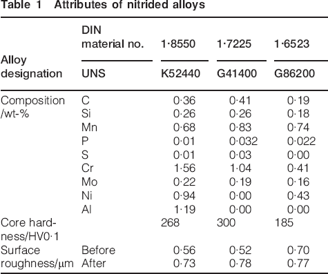
Nitriding treatments were conducted at a commercial plant in carefully controlled baths. Two cyanate baths were used: type 1 with 80 wt-% potassium cyanate and type 2 with 40 wt-% potassium cyanate. The balance in both baths was sodium carbonate. The nitriding operations were performed according to a test matrix shown in Table 2. The specimens were in a cylindrical form with 10 mm diameter and 60 mm length with rounded, hemispherical ends. One specimen of each alloy for each condition was used. Short treatment at low temperature (e.g. 0·5 h at 520°C) and long treatment at high temperature (e.g. 2 h at 630°C) were not investigated since adequate diffusion could not be satisfied at low temperatures and short times, and a very brittle microstructure would build up on the surface of the steels as a result of high temperatures and long times.
Nitriding test matrix*
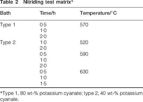
Type 1, 80 wt-% potassium cyanate; type 2, 40 wt-% potassium cyanate.
Characterisation
The microstructures of the nitrided parts were analysed to determine the compound layer thickness, diffusion depth, nitrogen concentration profile, nitride type and surface quality.
Small sections cut from the nitrided and unnitrided specimens were ground, polished and etched for microscopic observations. A 5% nital (5 vol.-%HNO3+95 vol.-% ethanol) solution was used for etching. A Nikon Eclipse LV150 optical microscope was used to observe the microstructural features of the specimens as well as to determine the thickness of the compound layer and the diffusion depth. Additionally, parts were analysed by a Philips XL30 ESEM-FEG scanning electron microscope (SEM). On this microscope, in addition to taking microphotographs, energy dispersive spectroscopy (EDS) analysis was conducted to determine the chemical composition of the nitrided specimens, especially the composition of the nitriding case.
The types of nitrides formed on the surface of the nitrided specimens were investigated by a Rigaku D/MAX Ultima+/PC X-ray diffractometer (XRD). Cu Kα radiation with 1·5418 Å wave length was used with 2θ angle within 30–80°.
The surface roughness of the specimens was measured by a Taylor–Hobson Surtronic 3+ profilometer before and after the nitriding to determine effect of the nitriding on the surface roughness.
Results and discussion
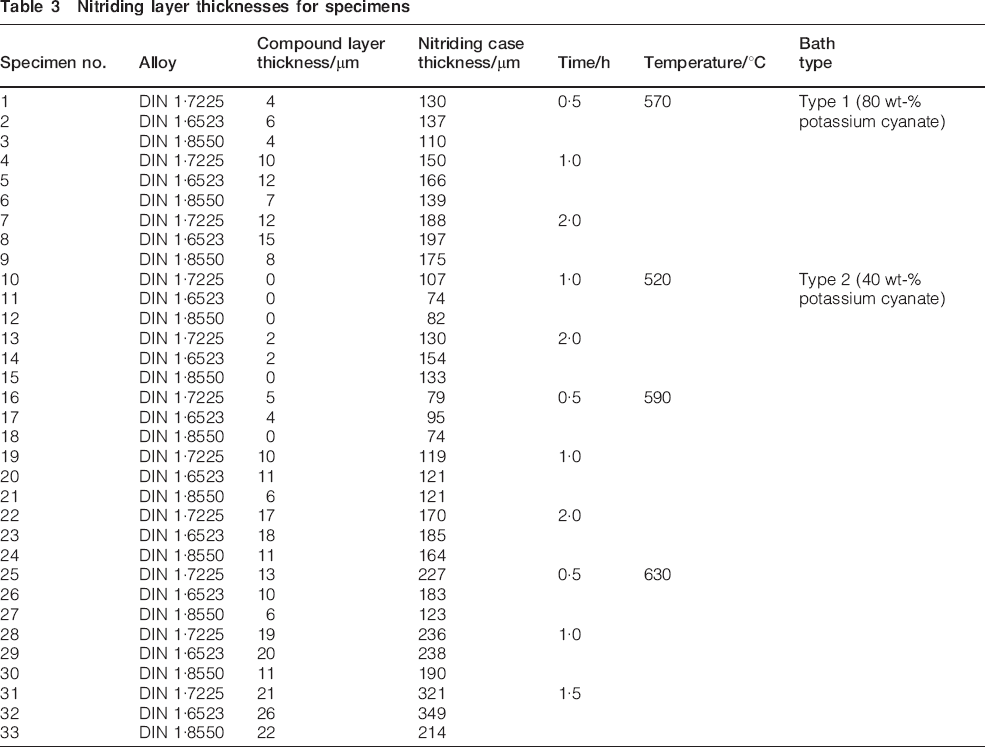
The nitriding trials have yielded different compound and diffusion layer thicknesses (data presented in Table 3) as a result of varied experimental parameters. Compound and diffusion layers can be seen by the optical microscope and SEM. The compound layer is differentiated by its white colour under a light microscope. The diffusion layer also displays coloration as well as a change in the grain structure. Owing to the nature of the nitriding process, the amount of nitrogen reduces from the surface towards the core of the material, as seen in Fig. 1, which shows an SEM microphoto (Fig. 1a) and measured nitrogen profile (Fig. 1b). The profile is determined by EDS, whose results are qualitative for low atomic number elements. As the nitrogen diffusion is dependent on time and temperature, high temperature and long treatments yield a thicker nitriding case and compound layer than low temperature and short treatments do (see Table 3).
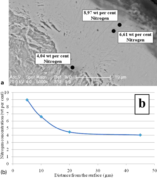
Nitrogen content in compound layer of specimen no. 33: data point in core, 45 μm away from surface, is not shown in microphoto but is seen in plot: a SEM microphoto showing EDS measurement locations; b measured data
Nitriding layer thicknesses for specimens
The selected specimens (nos. 5, 11, 17 and 32 in Table 3) were analysed by XRD technique to identify types of nitrides in the compound layer. While specimen no. 5 had a 12 μm thick compound layer and was treated in type 1 bath, the others had compound layer thicknesses varying from 0 to 26 μm and were treated in type 2 bath. The peak identification was performed using the International Center for Diffraction Data database in JADE 6·5+ XRD analytical software by MDI (Livermore, CA, USA). The XRD patterns produced from powders of ϵ and γ′ by Somers et al.14 and Ratajski et al.31 were also referred to. The XRD analysis suggests that, depending on the process temperature and bath composition, a nitrided surface consists of both ϵ and γ′ nitrides when the nitriding is carried out at and below 590°C. Nonetheless, the intensity of the ϵ nitride phase increases with the increase in process temperature. Therefore, nitriding at 630°C (in the austenitic phase field) results in the formation of completely ϵ nitride (see Fig. 2), a high nitrogen content phase, since more nitrogen diffuses into steel at this temperature. This is in line with the reported observations and diffusion kinetics of nitrogen in steel matrix.32 Still, deeper phases (e.g. γ′ and matrix) could be determined using an X-ray source with greater penetration depth.31,33
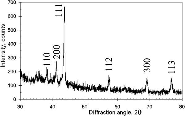
Pattern (XRD) of specimen no. 32 (DIN 1·6523 nitrided in type 2 bath at 630°C for 1·5 h): compound layer thickness is 26 μm, which is greatest among all specimens, and peak identification indicates ϵ phase
Effect of temperature and time
The experimental data presented in Table 3 indicate that an increase in process temperature yields a thicker compound layer. Similarly, a thicker case results in an increased temperature. Both are affected exponentially by temperature. The diffusion depth x is determined by the diffusion coefficient D of an element (e.g. nitrogen) in a matrix x∼(Dt)1/2, as predicted by Fick's law and the Wagner–Meijering equation.34,35 However, as it is very well known, the diffusivity of nitrogen in alloys varies. Thus, the use of diffusion coefficients to predict layer thicknesses during nitriding is hindered due to the lack of information on the concentration dependence of the diffusion coefficients of nitrogen in alloy steels. Although a ‘bulk’ diffusivity is reported for nitrogen in alloy steels,36 this approach is erroneous as it does not consider the diffusion kinetics separately in the compound layer, the diffusion zone and the matrix. Still, the penetration depth of nitrogen is associated with the content of alloying elements in steel. A decrease in the depth is reported with an increase in alloying element content.37 This is due to the larger capacity to bind nitrogen by nitride forming elements in steel, in accordance with the Wagner–Meijering equation.34,35 The large capacity to dissolve nitrogen in the diffusion zone leads to a larger flux of nitrogen atoms transferred from the compound layer to the diffusion zone; hence, less nitrogen can accumulate in the compound layer and sustain its growth.38 Therefore, DIN 1·8550 alloy, having higher content of nitride forming elements than the other two alloys, develops a thinner compound layer, as plotted in Fig. 3. The penetration depth of nitrogen is also proportional to process duration, so the compound layer thickness increases with nitriding time (see Table 3). As expected, a similar trend is observed for the case depth.
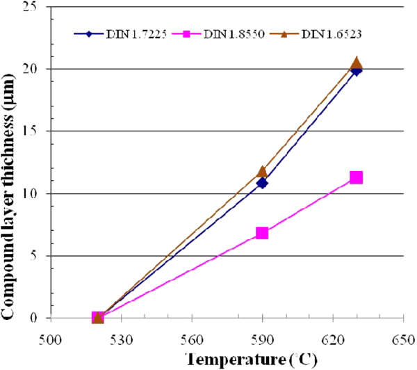
Compound layer thickness of specimens nitrided in type 2 bath at 520, 590 and 630°C for 1 h
Effect of bath composition
The cyanate content of a bath is responsible for the amount of nitrogen diffusion through the surface. Consequently, high cyanate content in a bath produces a thicker nitriding case, a higher surface hardness and a greater hardness depth.
Figure 4 presents the nitriding case thickness obtained in the two baths used in this research. The specimens nitrided for 1 h in type 1 bath at 570°C and in type 2 bath at 590°C have been selected to show the effect of bath composition. Thus, a comparison of the nitriding case thickness shows that the cases are noticeably thicker in the specimens nitrided in type 1 bath, even though the bath temperature is lower in type 1. A higher compound layer thickness is also observed with type 1 bath (see Table 3). This indicates the positive effect of high cyanate content on the nitrogen flux into a deeper region in the alloy. This result is expected because the type 1 bath enriches the surface concentration to higher nitrogen content and sets a higher concentration gradient towards the core. Thus, more nitrogen diffuses into the core of the alloy in this bath. Spies et al.39 have reported a similar observation, where they have found that an increase in the nitriding potential yields a thicker compound and diffusion layer.
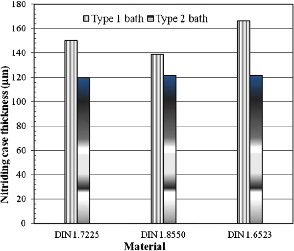
Nitriding case thickness of alloys in two baths: specimens nitrided in type 1 bath at 570°C for 1 h and in type 2 bath at 590°C for 1 h
It is worth noting that DIN 1·7225 and DIN 1·6523 develop thicker compound layer and nitriding cases than DIN 1·8550 after nitriding operations because of the greater content of nitrogen trapping alloying elements in the latter.
Effect of elements in steels
As given in Table 3, at the end of the 0·5 h nitriding in type 2 bath at 590°C, there is a 5 μm continuous compound layer on the surface of DIN 1·7225, but under the same conditions, there is a thinner and discontinuous compound layer formed on the surface of DIN 1·6523 alloy. On the other hand, there is no compound layer formation at all on DIN 1·8550 steel. The reason for this lies in the difference between the diffusion kinetics of nitrogen in these different alloys, as explained in the following paragraphs.
It is known that aluminium and chromium individually increases the surface hardness capability of steels after nitriding, whereas nickel alone does not increase the hardness.1 On the other hand, nickel with chromium and aluminium yields an excellent surface hardness.4 However, these three elements together reduce the nitriding case thickness, as expected, since they interact with nitrogen and trap it at the interface between the compound layer and the diffusion zone. Chromium contents <1·8 wt-% are said to be not very effective for nitride formation.27 Although the content in all the alloys in the current study is lower than the reported ‘threshold’ value, even though it may be very weak, there should still be an effect from the chromium content. Comparing specimens of DIN 1·7225 and DIN 1·8550 shows the combined effect of chromium, nickel and aluminium content on the compound layer and nitriding case thickness (DIN 1·7225 does not have Ni and Al, while DIN 1·8550 does, which also contains a higher amount of chromium). As already given in Table 3, DIN 1·8550 develops a thinner compound layer. Spies et al.39 have pointed out that an increase in chromium content decreases the diffusion layer thickness excessively. Furthermore, they have showed that the aluminium content has an effect similar to that of chromium. Therefore, this explains the reason for a thinner compound layer and nitriding case observed in DIN 1·8550 alloy.
The influence of carbon can be seen by comparing DIN 1·7225 (0·41 wt-%C) and DIN 1·6523 (0·19 wt-%C). The carbon content in an alloy affects the hardness, hardness depth and diffusion depth. It has been reported that carbides do not allow the nucleation of nitrides; specifically, they destabilise γ′ nitrides.24 In the high carbon cases, carbon reacts more effectively with the alloying elements to form carbide, so this limits the number and amount of elements to form nitrides. Thus, the hardness of the material decreases. Additionally, carbon atoms make nitrogen diffusion harder, and hence, the nitriding case thickness diminishes. As the data in Table 3 show, DIN 1·7225 and DIN 1·6523 have nearly the same compound layer and nitriding case thickness trends within the temperature range of the experiments for 1 h of nitriding. On the other hand, slightly lower compound layer thicknesses are observed for DIN 1·7225, especially for higher treatment temperatures (see Fig. 3). In fact, the reason for this slight difference is elucidated by Leppänen and Jonsson;8 they have indicated that carbon content is the major factor determining the diffusivity of interstitial elements, and the diffusion coefficient for low carbon alloys is higher than that for high carbon alloys.
A comparison of DIN 1·6523 and DIN 1·8550 illustrates the effect of aluminium, chromium and carbon. High chromium content and other alloying elements in DIN 1·8550 slow down the growth of the diffusion zone because the nitrogen penetrating into the diffusion zone is used for the formation of Cr and Al nitrides.40 Thus, the case depth in DIN 1·8550 is less than that in DIN 1·6523 in all the nitriding conditions. The nitriding case thickness measurements, as given in Table 3, is in line with this statement especially at the high temperature nitriding application.
Retained austenite
A light coloured layer is observed below the compound layer in specimen no. 32. These two layers are separated by a thin, dark line, as seen in Fig. 5. The light coloured layer has been observed in this particular specimen treated at 630°C, which is in the austenitic range. Hence, the formed layer is claimed to be the retained austenite. The austenite phase is retained due to quenching of nitrided specimens from the treatment temperatures. Krishnaraj et al.32 have reported that nitrogen and carbon lower the martensite start temperature, and this results in the retention of austenite in the transition zone between the compound layer and the diffusion layer. The retained austenite can transform to bainite and/or martensite with an increased hardness. However, this layer is not determined in DIN 1·8550 or in DIN 1·7225 specimens because of a higher eutectoid transformation temperature. For example, the eutectoid transformation temperature for DIN 1·8550 is reported to be around 640–650°C.41
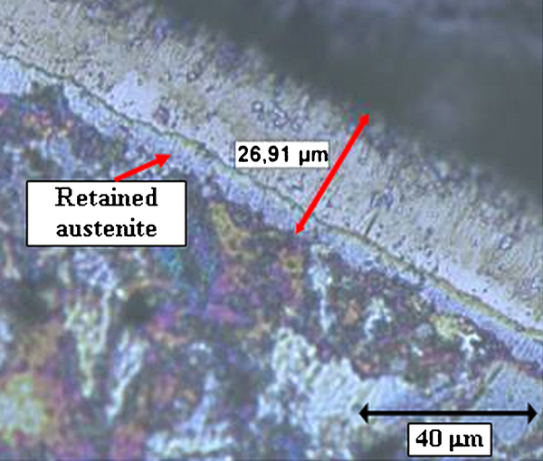
Retained austenite layer observed in DIN 1·6523 nitrided in type 2 bath at 630°C for 1·5 h
Porosity
Two types of porosity can be seen in the compound layer. Figure 6 presents an example for the discontinuous porosity and also the porosity channels formed perpendicular to the surface in the compound layer. The size of a pore increases at higher treatment temperatures, and they form as a result of the accumulation of interstitially dissolved nitrogen atoms at preferential sites, such as grain boundaries, to form molecular nitrogen.32,42 Indeed, the molecular nitrogen comes from the thermodynamic instability of the ϵ nitrides at high temperatures.42 It can qualitatively be said that more pores have been observed in samples treated at higher temperatures and for longer times in the current study. In addition, the channel porosity formation is triggered by the pressure, which reaches several kilobars exerted by interstitially dissolved nitrogen.21,27,32,43 The pressure results in the elongation of a pore into a pore channel. It is also reported that the porosity in salt bath nitriding is due to the corrosive attack on the surface.21,43
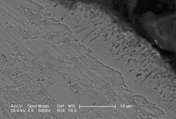
Discontinuous porosity (dark spots) and channel porosity (dark lines orthogonal to surface) in compound layer of DIN 1·6523
Surface roughness
A stylus profilometer has been used to measure the change in surface roughness caused by nitriding. Measurements show that, after nitriding, the average roughness value Ra has increased. The degree of the increase in the surface roughness varies with the material type. In the case of type 1 bath nitriding, the average surface roughness of DIN 1·6523 (specimen no. 5) steel has increased 10% from 0·7 to ∼0·77 μm, that of DIN 1·7225 (specimen no. 4) steel increased 50% from 0·52 to ∼0·78 μm and that of DIN 1·8550 (specimen no. 6) steel has increased 30% from 0·56 to 0·73 μm. The reason for the different initial surface roughnesses of unnitrided specimens comes from the difference in the core hardness of the specimens; harder specimens are machined easily and smoothly. However, after the nitriding process, a similar surface roughness value has been measured for the three alloys due to the property of the compound layer. As Korwin et al.42 pointed out, the reason for the high surface roughness after nitriding is a non-uniform nucleation and growth of nitride grains in the compound layer. The compound layer thicknesses, as determined by light microscopy, for specimen nos. 4, 5 and 6 are 10, 12 and 7 μm respectively. It seems that the final roughness is the least for the alloy with the thinnest compound layer, indicating that the surface roughness is more of a compound layer related property. In fact, although not explicitly stated, the discussion by Pye2 points to a similar result. Furthermore, Pye2 also linked the increase in surface roughness to the carbon content of an alloy. In fact, that is the observation in the current research. The magnitude of the increase in surface roughness is the greatest, as given above, for the alloy with the greatest carbon content (DIN 1·7225), and it is the least for the one with the lowest carbon content (DIN 1·6523). Similar observations were also reported for SiCN thin films.44,45 Of course, the surface roughness can also be associated with the ‘blowing up’ of the compound layer due to excessive nitrogen gas pressure.38,43,46
Conclusion
In this work, the effect of nitriding parameters, such as nitriding temperature, time, bath composition and alloy composition, on the nitriding case formation has been investigated. Three different alloys have been chosen and nitrided in two different salt baths for four different nitriding durations at four different process temperatures. Microstructural observations have shown the influence of the mentioned parameters on the compound and diffusion layer formation. Higher nitriding temperatures, times and bath compositions give rise to more nitrogen flux into the steels and hence yield a thicker nitriding case. Furthermore, as the compound layer thickens, it becomes ϵ type. The data analyses have indicated that especially aluminium and chromium containing alloys have formed thinner cases. Discontinuous and channel type porosity have been observed. It has been also found that the surface roughness of specimens has increased after nitriding and depended on the case thickness and carbon content of an alloy.