
Abstract
Two new orientation relationships between β-Mg2Sn precipitates and α-Mg matrix have been observed by transmission electron microscopy. One is (1 1 0) β //(0 0 0 1) α , [0 0 1] β //[1 −1 0 0] α , and the other is (1 1 0) β //(0 0 0 1) α , [−1 1 −1] β //[1 −1 0 0] α . The precipitates with both orientation relationships exhibit a lath shaped morphology, with the long axis lying along [1 1 −2 0] α . The morphology is interpreted by a three-dimensional near coincidence sites model.
Introduction
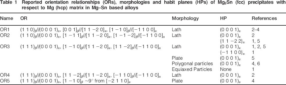
A Mg–Sn based system is a candidate for heat resistant Mg alloys since the thermal stability of the major precipitate in this system, i.e. Mg2Sn, is comparative to that of the main precipitates in Mg–RE based systems. Moreover, Mg–Sn based alloys are more cost effective than Mg–RE based alloys. The Mg2Sn phase, designated as β phase, has a face centred cubic (fcc) structure with a lattice parameter of aβ = 0·676 nm,1 while Mg, designated as α phase, has a hexagonal close packed (hcp) structure with lattice parameters of aα = 0·321 nm and cα = 0·521 nm. The lattice parameters of the two phases are considerably different (aβ/aα≈2·1), and hence, the Mg2Sn/Mg system is regarded as a large lattice misfit system. Five orientation relationships (ORs) in this hcp/fcc system have been reported in the literature, as listed in Table 1.1–6 Four of the ORs were first reported in Mg–Sn binary alloy, i.e. OR1–OR4. Further alloying with Na or Zn resulted in a reduced size and uniform distribution of Mg2Sn precipitates. However, no new ORs due to the additions of microalloying elements were reported. 1 3 5 1,3,5,7 Recently, Zhang et al.4 found a different OR, i.e. OR5, as described by (1 1 1) β //(0 0 0 1) α , [1 −1 0] β deviates ∼9° from [−2 1 1 0] α from a study of an Mg–5·29Sn–0·29Mn–0·22Si (wt-) alloy. This OR is an irrational OR since it cannot be described by a parallelism of low index planes or directions. It is possible that the addition of Mn or Si affects the OR between Mg2Sn precipitates and Mg matrix.
Reported orientation relationships (ORs), morphologies and habit planes (HPs) of Mg2Sn (fcc) precipitates with respect to Mg (hcp) matrix in Mg–Sn based alloys
The fcc and hcp are common crystal structures of either matrix or precipitates in many metallic materials. The precipitation crystallography, including OR and crystallographic morphology, may significantly affect the mechanical properties of the materials, especially Mg alloys with rather limited slip systems at room temperature. Therefore, detailed knowledge about precipitation crystallography is essential for age hardenable Mg alloys. Zhang et al.8 made a comprehensive study on the crystallography of simple hcp/fcc systems. They mainly investigated small lattice misfit systems with 1·25⩽aF/aH⩽2·0, where aF and aH denote the parameters of the fcc and hcp phases including Mg respectively. According to their conclusions, there were seven possible ORs, but none of them was preferred when 1·56⩽aF/aH⩽2·0.8 In the Mg2Sn/Mg system, aβ/aα is close to 2·0, so the criterion given by Zhang et al.8 is not applicable to interpretation of the observed ORs listed in Table 1.
In the present study, two new ORs between Mg2Sn precipitates and Mg matrix have been observed in an Mg–Sn–Mn alloy with high Mn contents. The present paper will present the experimental results of the ORs and the corresponding crystallographic morphology using transmission electron microscope (TEM). The observations will be interpreted by a simple misfit analysis.
Experimental
The Mg–7·5Sn–2·2Mn (wt-) alloy was prepared by die casting and homogenised at 450°C for 48 h before being cut into small samples. The samples were solution heat treated at 480°C for 0·5 h, quenched into water at room temperature and then aged at 200°C for 270 h. The specimens for TEM were prepared by twin jet electropolishing in an electrolyte consisting of 6 mL perchloric acid and 274 mL alcohol at −50°C and 15 mA. The specimens were examined in a JEOL JEM-200CX operating at 200 kV. The ORs of the precipitates and Mg matrix are characterised using selected area electron diffraction. The facets of the precipitates are measured from edge on directions.
Results
Many Mg2Sn precipitates in the aged samples are found to have a lath shape with the HP parallel to (0 0 0 1) α . Two of the reported ORs listed in Table 1 have been observed. One is OR1, i.e. (1 1 0) β //(0 0 0 1) α , [0 0 1] β //[1 1 −2 0] α , [1 −1 0] β //[−1 1 0 0] α . The other is OR2, i.e. (1 1 0) β //(0 0 0 1) α , [1 −1 1] β //[1 1 −2 0] α , [1 −1 −2] β //[−1 1 0 0] α . Viewed along [0 0 0 1] α zone axis, the Mg2Sn precipitates with both the ORs have a rectangular shape, but their major side facets are different. The major side facet of the precipitate with OR1 is parallel to (−1 1 0 0) α and (1 −1 0) β , which is consistent with previous studies.2–4 However, the major facet of the precipitate with OR2 is not parallel to any low index plane of either the precipitates or the matrix. Such a facet is said to have an irrational orientation. For convenience, Mg2Sn precipitates are denoted by their ORs with respect to Mg matrix, e.g. those with OR1 are called OR1 type Mg2Sn precipitates.
While there are many lath shaped Mg2Sn precipitates with their major side facets parallel to (−1 1 0 0) α //(1 −1 0) β , a careful TEM investigation on the OR of these precipitates has revealed that some of them do not belong to the OR1 type. Two new ORs were observed. Figure 1a shows two parallel lath shaped precipitates in contact with each other. Both precipitates have the same OR with respect to the Mg matrix. An overlapped diffraction pattern of one of the precipitates and Mg matrix is shown in Fig. 1b. In this pattern, the electron beam is parallel to the [0 0 0 1] α zone axis of the Mg matrix. In addition to the diffraction spots from the Mg matrix, a set of diffraction spots can be indexed according to the [1 1 0] β zone axis of Mg2Sn. Some low index diffraction spots in this zone axis are connected by white lines. The other diffraction spots are from double diffraction. According to Fig. 1b, (0 0 2) β is parallel to (1 −1 0 0) α . Therefore, the OR between the lath shaped precipitates and the Mg matrix in Fig. 1a can be described by (1 1 0) β //(0 0 0 1) α , [0 0 1] β //[1 −1 0 0] α , [1 −1 0] β //[1 1 −2 0] α . This new OR will be called OR6. The number of OR6 type Mg2Sn precipitates is observed to be comparable to that of OR1 type precipitates. This indicates that OR6 is also a major OR of Mg2Sn precipitates.
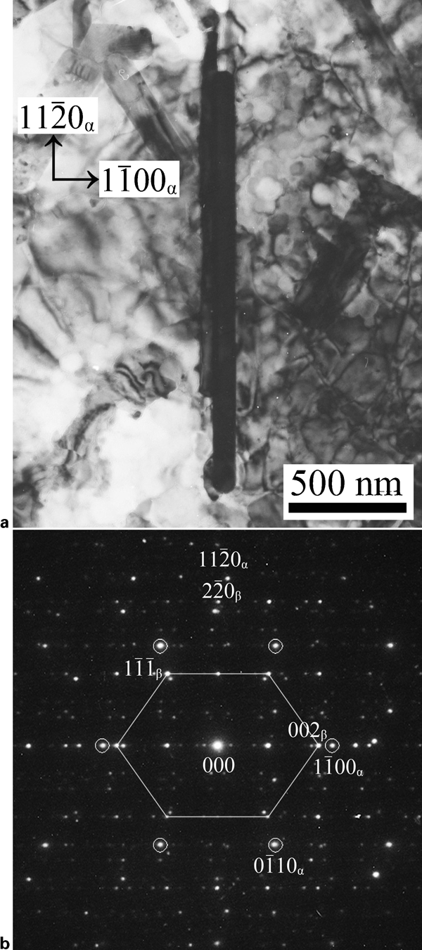
Transmission electron microscope observation of Mg2Sn precipitates along [0 0 0 1] α //[1 1 0] β zone axis
Another new OR of Mg2Sn precipitates with morphology similar to those of OR1 and OR6 types is shown in Fig. 2. The overlapped diffraction pattern taken from the lath shaped precipitate and its matrix in Fig. 2a is shown in Fig. 2b. This diffraction pattern of the Mg matrix can be indexed by the [0 0 0 1] α zone axis. In addition, a set of diffraction spots can be indexed by the [1 1 0] β zone axis of Mg2Sn. Line segments were again used to mark the spots from Mg2Sn in Fig. 1b. The other diffraction spots are from double diffraction. According to Fig. 2b, (−1 1 −1) β is parallel to (1 −1 0 0) α . Therefore, the OR between the lath shaped precipitate and the Mg matrix in Fig. 2a can be expressed as (1 1 0) β //(0 0 0 1) α , [−1 1 −1] β //[1 −1 0 0] α , [−1 1 2] β //[1 1 −2 0] α . This new OR will be called OR7. The OR7 type precipitates are less often observed than the OR6 type precipitates.
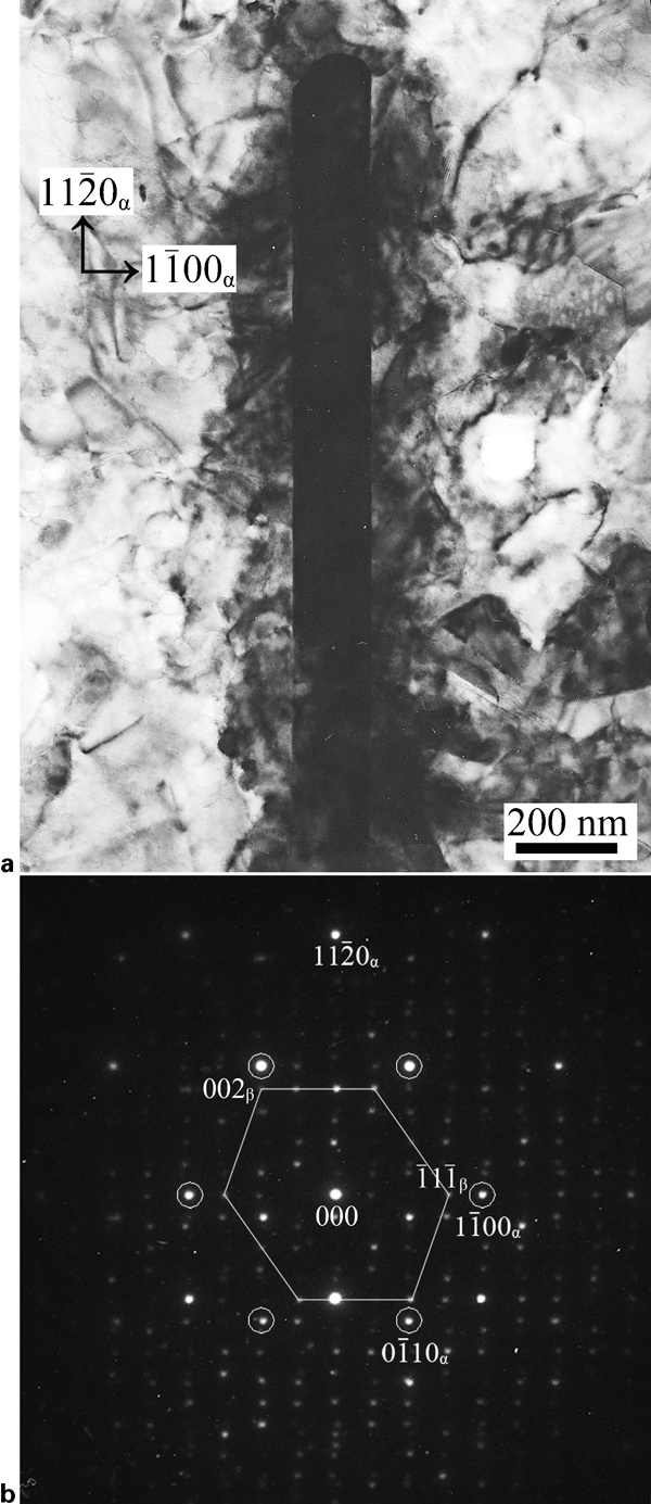
Transmission electron microscopy observation of a Mg2Sn precipitate along [0 0 0 1] α //[1 1 0] β zone axis
It is interesting to note that both new ORs share (1 1 0) β //(0 0 0 1) α with OR1 and OR2. While [1 −1 0 0] α is parallel to [−1 1 0] β for OR1 and to [−1 1 2] β for OR2, as shown in Table 1, it is parallel to [0 0 1] β for OR6 and to [−1 1 −1] β for OR7. There is a rotation of 90° between OR1 and OR6, and between OR2 and OR7, about the rotation axis of [0 0 0 1] α (//[1 1 0] β ).
The lath shaped Mg2Sn precipitates with (0 0 0 1) α as HP and (1 −1 0 0) α as major side facet are not distinguishable according to their morphologies with respect to the Mg lattice. However, the morphology is not crystallographically equivalent with respect to the Mg2Sn lattice. While the HPs are identical for both new types of precipitates, the major side facets are parallel to (0 0 1) β and (−1 1 −1) β for OR6 and OR7 types of precipitates respectively. The reason for the co-existence of precipitates with similar shape and different ORs is discussed below based on an interfacial matching analysis.
Interpretation of crystallographic morphology
An interface of good matching is presumably associated with a low interfacial energy.9 By interpenetrating two lattices, the lattice points from different lattices will form a pattern of good and poor matching. The positions at which points from different lattices overlap with each other are called coincidence sites. They represent the perfect matching locations. It is conceivable that a plane containing densely regular coincident sites is energetically more favourable than a plane containing scattered sites. A periodical distribution of coincidence sites forms a coincidence site lattice (CSL).10 However, an exact CSL can form only if the ratio of the lattice parameters of the two phases is special. In a heterophase system with a large lattice misfit, the requirement for lattice parameters is seldom satisfied, so a CSL is unlikely to form.11–13 To allow a small degree of misfit, we have evaluated the interfacial matching status according to the distribution of near coincidence sites (NCS), as suggested by Liang et al.14 Planes or directions containing dense NCS are likely to be favoured by nature.14–16 The threshold of the NCS is taken to be 15aα, where aα is the smallest lattice distance of α-Mg. If the distance between two points from different lattices is smaller than 15aα, then either of the points is considered to be an NCS. The coordinate system used for calculation is set to be x//[1 −1 0 0] α , y//[1 1 −2 0] α and z//[0 0 0 1] α . The density of the NCS in a plane is evaluated by the number of NCS per unit area. The thickness of the area slice is selected to be the diameter of a Sn atom, which is 0·28 nm. To avoid noticeable variation of NCS density due to area selection, the minimum area is chosen to be large enough, and the shape of the area is chosen to be circular. The NCS density is calculated for changing orientations of interfaces in steps of 0·5°. The highest density is unified to be 1. Other densities are displayed as relative densities with respect to the unified value. The calculated results of relative NCS densities for OR6 and OR7 are shown in a stereographic projection along the z axis in Fig. 3a and b respectively. In these figures, a warmer coloured region indicates a higher NCS density.
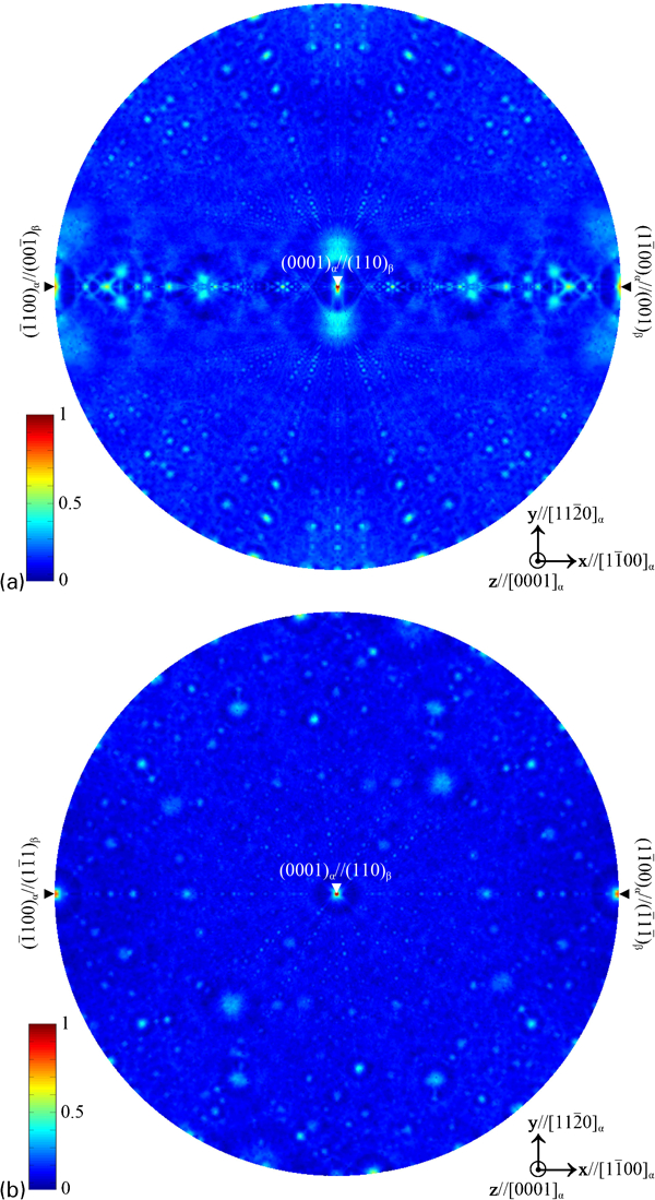
Stereo projection of planar density of NCS along [0 0 0 1] α
It can be seen from Fig. 3a that the plane with the highest NCS density is parallel to (1 1 0) β //(0 0 0 1) α and that with the second highest density is parallel to (0 0 1) β //(1 −1 0 0) α . This indicates that (1 1 0) β //(0 0 0 1) α is preferred as the HP, and (0 0 1) β //(1 −1 0 0) α is preferred as the major side facet. The intersection line of (1 1 0) β //(0 0 0 1) α and (0 0 1) β //(1 −1 0 0) α is parallel to [1 −1 0] β //[1 1 −2 0] α , which is the long axis of the OR6 type precipitate. The misfit between [1 −1 0] β and [1 1 −2 0] α is only 0·7. It is reasonable that [1 −1 0] β //[1 1 −2 0] α will be contained in the preferred facets. Therefore, the observed morphology for OR6 can be interpreted consistently in terms of good matching, as evaluated by the NCS density.
In Fig. 3b, the plane with the highest NCS density is also parallel to (1 1 0) β //(0 0 0 1) α and that with the second highest density is parallel to (−1 1 −1) β //(1 −1 0 0) α . This indicates that (1 1 0) β //(0 0 0 1) α is preferred as the HP, and (−1 1 −1) β //(1 −1 0 0) α is preferred as the major side facet. The intersection line of (1 1 0) β //(0 0 0 1) α and (−1 1 −1) β //(1 −1 0 0) α is parallel to [−1 1 2] β //[1 1 −2 0] α , which is the long axis of the OR7 type precipitate. Therefore, the observed morphology for OR7 can also be interpreted consistently in terms of the NCS density. The misfit between [−1 1 2] β /2 and [1 1 −2 0] α for OR7 is −14·0, much larger than that between [1 −1 0] β and [1 1 −2 0] α for OR6. This helps to explain why OR6 type precipitates are more frequently observed than OR7 type precipitates.
The analysis above reveals that a plane associated with a peak density of NCS is also associated with an energy cusp in interfacial energy. This explains why these facets are observed. By now, seven ORs of Mg2Sn precipitates have been found in Mg–Sn based alloys. It is possible that each OR lies at a shallow cusp of energy. The variety of the ORs may be caused by a disturbance of the complex atomic structure of Mg2Sn or a strain field presented in the nucleation and the early growing stages of the precipitate.
Conclusions
Two new ORs of the Mg2Sn precipitates have been characterised with TEM. They are (1 1 0) β //(0 0 0 1) α , [0 0 1] β //[1 −1 0 0] α , [1 −1 0] β //[1 1 −2 0] α (OR6) and (1 1 0) β //(0 0 0 1) α , [−1 1 −1] β //[1 −1 0 0] α , [−1 1 2] β //[1 1 −2 0] α (OR7). Precipitates with both types of ORs exhibit a lath shaped morphology with long axis parallel to [1 1 −2 0] α . Their HPs are identically parallel to (1 1 0) β //(0 0 0 1) α . However, their major side facets are different, which is parallel to (0 0 1) β //(1 −1 0 0) α for OR6 and (−1 1 −1) β //(1 −1 0 0) α for OR7. The crystallographic morphology is interpreted according to the planar density of NCS. For OR6 and OR7, the densities of NCS in the HPs are always the highest, and those in the major side facets are the second highest. The intersection line of (0 0 0 1) α and (1 −1 0 0) α is parallel to [1 1 −2 0] α , i.e. the long axis. The observations can be consistently explained in terms of the NCS density.
Footnotes
Acknowledgements
The experimental alloy was prepared by the group of Professor R.-S. Chen from the Institute of Metal Research, Chinese Academy of Science. Valuable discussions from Professor R.-S. Chen and L. Gao are gratefully acknowledged. The present work made use of the resources of the Beijing National Center for Electron Microscopy and was supported by the National Basic Research Program of China (grant no. 2009CB623704) and the National Nature Science Foundation of China (grant no. 50971076).