
Abstract
Atomistic simulations have been used to investigate the effect of a spatially distinct defect, i.e. stacking fault tetrahedron (SFT), on the inception of plastic deformation in a perfect copper single crystal during nanoindentation. An SFT positioned within a volume under significant stress from indentation lowers the stress required for dislocation nucleation by up to 50 from that of the perfect crystal when the nucleation event occurs at the SFT. The orientation of the SFT affects the required load for the initiation of plastic deformation and provides an envelope for the effect an SFT can have in weakening an otherwise perfect crystal. The weakening effect of the upward SFT vanishes faster than the downward SFT when it is lowered along the indentation axis. The load at the onset of plasticity changes with position, and the load drop after the inception of plastic deformation increases with SFT distance from the surface.
Introduction
Stacking fault tetrahedra (SFTs) are common defects formed in fcc crystals under a variety of treatments, such as large plastic deformation, 1 quenching from high temperatures,2,3 irradiation 4 and focused ion beam (FIB) milling. 5 Stacking fault tetrahedra are a special shape of vacancy clusters whose stability depends on the number of initial constituent vacancies. 6 Other structural point defects, such as single and di-vacancies, and impurity atoms can also be formed in the above mentioned processes. In a sufficiently small volume of a material, in which dislocations are likely not present, these internal defects can alter the mechanical response by lowering the stress required for the initiation of plastic deformation.7–12 Several studies have shown that the onset of plasticity in a low dislocation density material is the result of the nucleation of dislocations in the materials either homogeneously from the perfect lattice or heterogeneously from the existing defects; these defects may be point defects or pre-existing dislocations in materials.13–20 The data presented in the recent paper of Salehinia and Bahr 12 showed that among the different point defects in copper single crystal, the SFT has the largest effect on the yield stress, reducing the pressure at the onset of plasticity in nanoindentation test by almost half of that for the perfect crystal. Figure 1 includes a typical comparison on the per cent reduction in pressure at the onset of plasticity (with respect to that for a perfect crystal) for different types of point defects (single vacancy, self-interstitial atom, di-vacancy and SFT) in that paper. As the SFT has the biggest impact on the mechanical response of the material in the case of incipient plasticity, it is necessary to explore the governing deformation mechanisms in the presence of this defect. Literature on the effects of SFT on the mechanical response of materials is mostly limited to the formation of this defect or its interaction with other structural defects, mainly dislocations.3,21,22
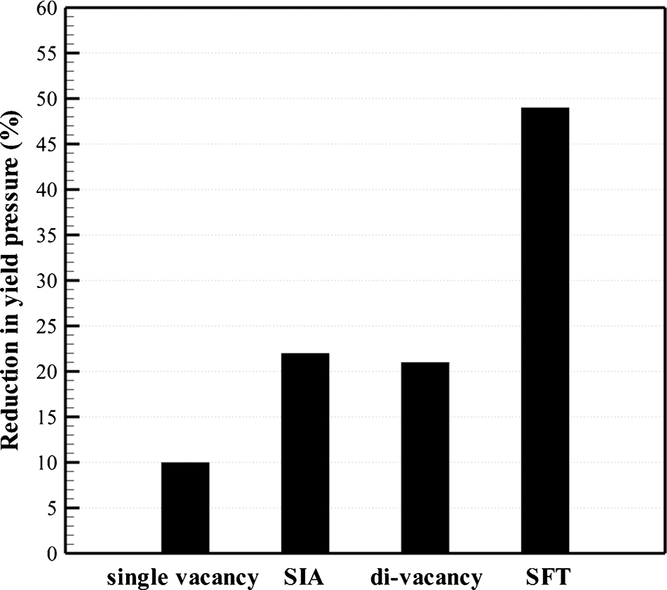
Maximum per cent reduction in yield pressure (contact pressure at onset of plastic deformation) in nanoindentation tests on copper single crystals for different point defects. 12
Nanoindentation experiments are capable of testing extremely small volumes of materials containing a low amount of pre-existing dislocations.23,24 In the absence of pre-existing dislocations, plastic deformation is mainly controlled by the nucleation of dislocations. If the surface of a sample is flat and has few significant asperities, then the maximum shear stress during an indentation test which begins in an elastic manner is in the bulk of the material. 25 This makes small scale indentation specifically suitable for studying the effect of internal defects on the mechanical behaviour of materials. In indentation testing, the onset of plasticity is seen as either an excursion in a load–displacement graph in load control mode or load drop in load when indentations are run in displacement control mode.23,26
In the present paper, atomistic simulations are used to investigate the effect of SFT on the inception of plastic deformation in copper. Different orientations of this defect are considered and deformation mechanisms are used to explain the observed mechanical response in the load–displacement curves in a nanoindentation test.
Modelling
Molecular dynamics, as implemented in large scale atomic/molecular massively parallel simulator (LAMMPS) code27,28 using the embedded atom method,
29
were performed to model nanoindentation tests on copper single crystal having SFT as an internal defect. The size of the simulation box was 20×20×20 nm3, containing ∼680 000 atoms. The indenter radius was varied between 6 and 15 nm. Although these sizes are much smaller than the indenter radii in experiments, the applied approach in the present work assures getting similar results for larger sample and indenter sizes. The indenter was modelled as a rigid spherical tip using a quadratic repulsive force.
11
Using a deformable indenter in the simulations increases the computational cost of the simulations without a remarkable effect on the overall behaviour of the crystal with or without a defect. The indentation was performed along the [111] direction (Y axis), while the X and Z axes are along  and
and  directions. The top face is allowed to move, and the bottom and side faces are fixed within 5 Å. An initial relaxation was applied for 10 000 molecular dynamic steps (10 ps) using a time step of 1 fs. The indenter speed was 10 m s−1. The temperature of the system was kept close to 0 K to reduce temperature effects. To visualise defects, the centrosymmetry technique
11
was employed. To see particular defects, atoms in the perfect lattice (with a centrosymmetry parameter (CSP) <0·3) are not shown in atomistic configurations represented in the results.
directions. The top face is allowed to move, and the bottom and side faces are fixed within 5 Å. An initial relaxation was applied for 10 000 molecular dynamic steps (10 ps) using a time step of 1 fs. The indenter speed was 10 m s−1. The temperature of the system was kept close to 0 K to reduce temperature effects. To visualise defects, the centrosymmetry technique
11
was employed. To see particular defects, atoms in the perfect lattice (with a centrosymmetry parameter (CSP) <0·3) are not shown in atomistic configurations represented in the results.
The SFTs, centred on the indentation axis, were generated by relaxation of a triangular Frank loop platelet of vacancies in one of the {111} planes,
30
containing 55 vacancies, 10 on each edge. The edge length of the resulting SFT is ∼2·2 nm, which is similar to the size of SFTs in copper observed in the experiments.
1
The density of the SFT in the modelling is close to 10
23
m−3, which was reported for copper.
31
It should also be noted that the obtained results in the present paper are applicable to much bigger sample sizes for which the SFT density is even more realistic. Upward and downward SFTs were generated by removing the initial triangle of vacancies in (111) and  close packed planes respectively. Figure 2 shows the configuration of the triangle of the vacancies before relaxation (Fig. 2a) and the relaxed structure having a downward SFT (Fig. 2b).

Atomistic configurations of simulation box a before and b after relaxation showing formation of downward SFT from triangle of vacancies in
plane: atoms are colour coded using centrosymmetry parameter
Results and discussion
For the simulations using an indenter with a radius of 6 nm, Fig. 3 shows the load–displacement curves for a perfect crystal and crystals with SFTs having different orientations, in upward and downward directions and positioned on the indentation axis at the 9th layer from the surface. The shapes of the SFTs are also shown in this figure.
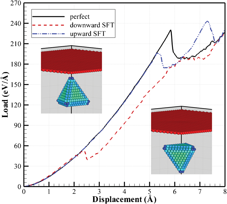
Load–displacement curves for perfect crystal and crystals having upward and downward SFTs. Insets show shape of each SFT. Indenter radius is 6 nm, and SFTs are centred on indentation axis at ninth layer from surface
The orientation of the SFT affects the amount of reduction on the yield load at the onset of plasticity. This behaviour is best explored using atomistic visualisation to define the differences in the mechanisms governing the inception of plasticity. In all the simulations with defect in the crystal, the onset of plastic deformation has been identified as the point in the loading sequence when dislocations already nucleated from the defect reach the top surface of the crystal. This ensures that they cause permanent deformation; before this condition, it is possible for partial dislocations to reverse during unloading in the simulation and provide no permanent deformation. Figure 4 shows the deformation mechanisms for crystals having SFT on both orientations. The SFTs are centred at the twelfth layer, and the indenter size is 6 nm. For both orientations, the deformation initiates with an “unzipping” of the SFT in the direction with the highest stress, which in the initial state of deformation is a high compressive stress in the loading direction. The deformation mechanisms are different for the considered orientations after unzipping the SFT is complete. For the downward facing SFT, unzipping is followed by propagation of dislocations on three {111} planes creating SFT, toward the top surface of the crystal. On the other hand, for the upward SFT after unzipping the SFT, the dislocations continue to propagate into the bulk of the material in two slip planes until dislocations start to propagate toward the top surface in another slip plane. In the case of the upward oriented SFT, the movement of dislocations into the bulk of the crystal delays the onset of plasticity, and hence, the required load for the initiation of plastic deformation is larger than that associated with the downward SFT. An important observation in here is that for both orientations, the SFT is the source of dislocation nucleation. This indeed depends not only on the relative position of SFT to the indenter but also on the orientation of the SFT.
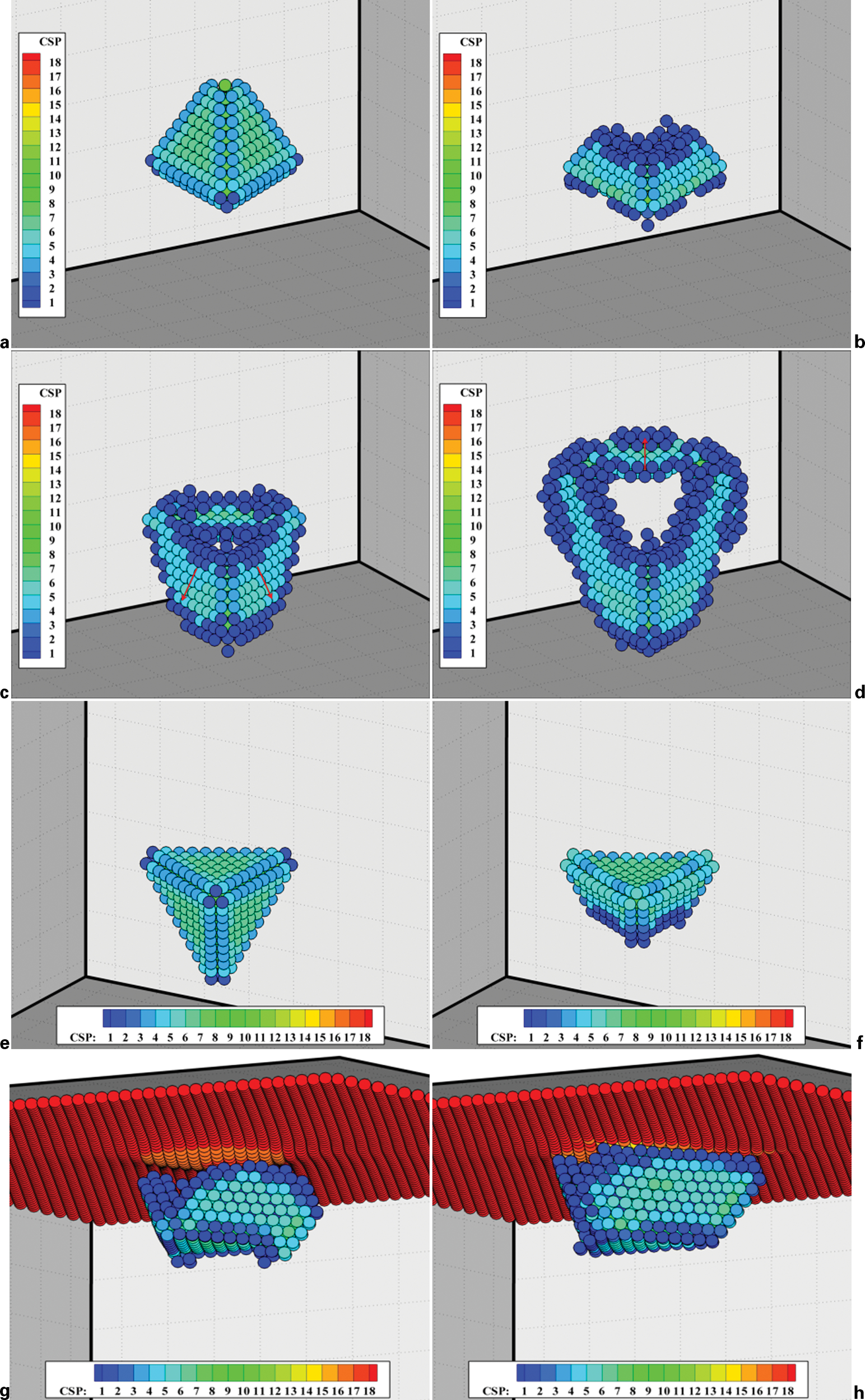
a–d initial upward SFT, unzipping SFT, propagation of dislocations toward bottom surface and propagation of dislocation toward top surface; e–h initial downward SFT, unzipping SFT, propagation of dislocations toward top surface, dislocations hit the top surface.
Figure 5 shows the variation of contact pressure ratio at the onset of plastic deformation for upward and downward SFTs centred on the indentation axis at different layers. The contact pressure ratio is the ratio of the contact pressures i at the onset of plastic deformation of a crystal with SFT and a perfect crystal. The downward SFT can reduce the pressure at the onset of plastic by up to 50 of that for the perfect crystal. When the SFT defect is located further from the indentation surface, the effect on the yield load at the onset of plasticity is lessened. Furthermore, the weakening effect of the upward SFT vanishes much faster than that of the downward SFT. Visualisation of the atomistic configuration before the onset of plasticity in Fig. 6 shows that when an upward SFT is centred at the fifteenth layer on the indentation axis, nucleation of dislocations far from the SFT accompanies the unzipping of the SFT. Nucleation of dislocations from areas without initial defects will be referred to as homogeneous dislocation nucleation; at this point, the crystal is behaving identical to the defect free crystal. When the SFT is placed at the ninth or twelfth layers, the deformation is heterogeneous, and dislocations are formed from the defect.
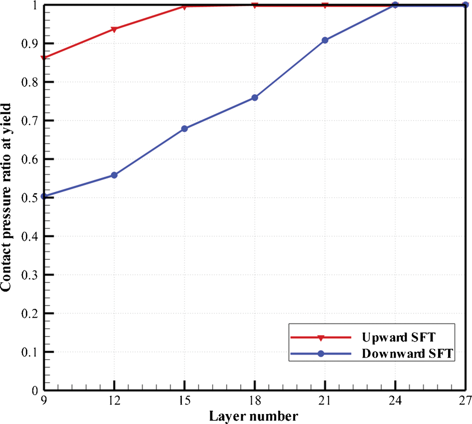
Variation of contact pressure ratio at onset of plasticity versus depth of centre of SFT for upward and downward orientations; indenter radius is 6 nm
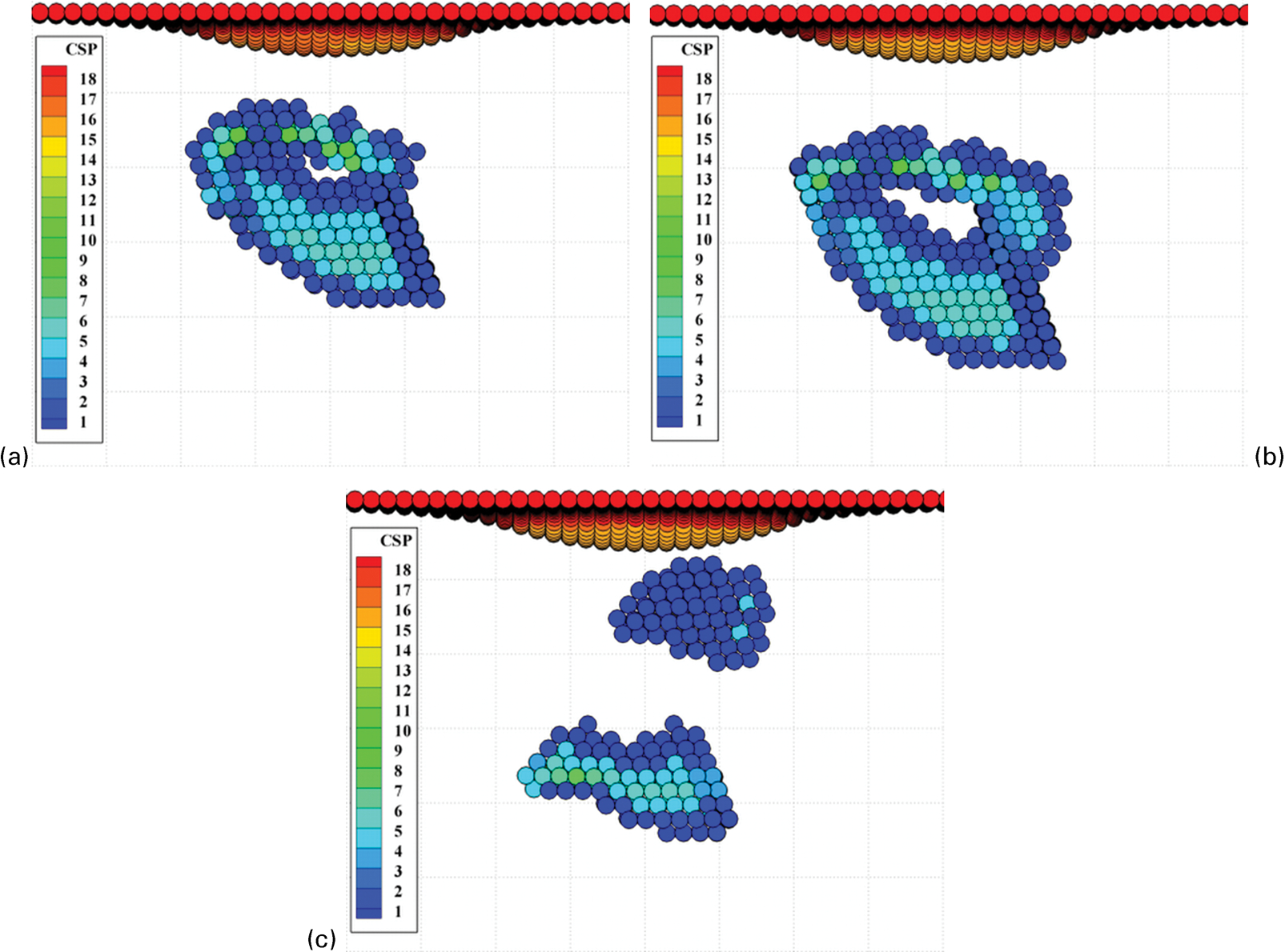
Atomic snapshots showing deformation mechanisms for upward SFT centred at a ninth, b twelfth and c fifteenth layers; indenter radius is 6 nm
As the effect of the downward SFT on the yield load is much bigger than that of the upward SFT, the present study continues with the focus on the effect of downward SFT on the mechanical behaviour of the crystal. Simulations were made using an indenter with a radius of 15 nm. Using this indenter size, it is possible to check the consistency of the results for different indenter sizes (the change in indenter size is a factor of 2, which makes it within a factor of 3 of experimentally achievable tip radii). Second, the SFT can be placed in much deeper layers from the surface as the ratio of contact area/position is a controlling factor in the position sensitivity of the defects.
Figure 7 shows the load–displacement curves for a perfect crystal and for crystals with different centre positions of SFT along the loading axis. Even an SFT centred at the forty-second layer can weaken the material in the case of larger tip radius. It is also observed that the amount of load drop at the inception of plastic deformation is increased as the defect is located in the lower layers. This behaviour is supported by the geometrically necessary loading curve, which is defined by the material properties (modulus and strength) and geometry of the nanoindentation test, including indenter shape and indenter size. 32 As the onset of plastic deformation deviates from the geometrically necessary elastic–plastic curve, the elastic strain energy is increased, leading to larger load drops needed to reach the geometrically necessary load–depth curve once plasticity has initiated.
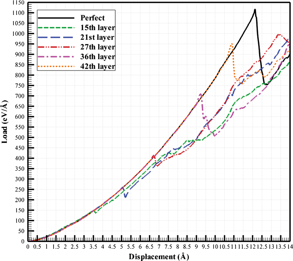
Load–displacement graphs of nanoindentations on (111) copper single crystal including SFT centred on indentation axis at different layers; indenter radius is 15 nm
Conclusions
Atomistic simulations have been performed to explain the mechanical behaviour seen in the nanoindentation test of copper single crystal having SFT as an internal defect. Different orientations of the defect have been examined, and it is found that the downward SFT has a larger effect on the mechanical behaviour of the copper single crystal than an upward oriented SFT. This allows upper and lower bounds to be identified for the possible effects this defect has on the inception of plasticity. The weakening effect of the defect vanishes much faster when the SFT is oriented in the upward direction than when it is in a downward orientation. Atomistic configurations of the deformation mechanisms using centrosymmetry analysis were used to explain this behaviour. The load at the onset of plasticity and the magnitude of the load drop after the inception of plastic deformation increase as the SFT is positioned further from the surface, showing the effects of spatially distinct defects on yielding during nanoindentation.
Footnotes
Acknowledgement
Financial support for the present research was provided by the National Science Foundation under grant no. DMR 0907378.
1
Contact pressures are calculated as , where R is the indenter radius, and F and d are the load and indentation depth at the onset of plasticity respectively.