
Abstract
Microstructure refinement of ternary eutectic Fe40Ni40B20 alloy in undercooling and rapid cooling solidification has been studied. In natural cooling conditions, two kinds of microstructure refinement take place with increasing undercooling. For melts with the same undercooling, the as solidified microstructure refines first and then coarsens with increasing cooling rate. On this basis, repeatable experiments show that the combination of melt undercooling at ∼50 K with Ga–In alloy bath rapid cooling produces very fine eutectic cells (∼5 μm in diameter with the lamellae spacing <100 nm). This indicates that an appropriate initial melt undercooling combined with a proper cooling rate is a potential way to produce a bulk nanostructure in ternary Fe40Ni40B20 alloy.
Introduction
Non-equilibrium solidification processes, which are convenient methods of obtaining the non-equilibrium state of materials, have been widely used to produce novel metastable phases and microstructures.1,2 In the past several decades, great progress has been made in the analysis of non-equilibrium solidification processes and consequences.3,4 Usually, two kinds of technologies are adopted to achieve the non-equilibrium solidification, i.e. rapid cooling and undercooling technologies. Rapid cooling leads to rapid solidification of the melts kinetically and gives the non-equilibrium microstructures. Undercooling experiments achieve rapid solidification at slow cooling rates by suppressing nucleation of the new phase thermodynamically.
Grain refinement in non-equilibrium solidification of binary alloys, such as Ni–Cu,4–6 Fe–Ni,7 Fe–Co8 and Co–Pd,9 has been studied widely, where dendrite remelting and fragmentation were supposed to be the main mechanisms. For multielement alloys, the phase formation and their performances were mainly focused on, while the microstructure refinement has seldom been studied. FeNiB alloys are one of the simplest metal–metalloid ternary eutectic alloys. They have good mechanical and physical properties. These properties could be largely improved with a refined microstructure.10–13 Microstructure formation for Fe40Ni40B20 molten droplets was studied by Vitta et al. using melt fluxing method.14 Subjected to high initial melt undercooling (ΔT), metastable phases (Fe, Ni)23B6 and Fe2Ni2B were formed; neither an amorphous phase nor a nanostructure was formed directly from the melt. Crystallisation of the amorphous Fe40Ni40B20 alloy was also studied by several authors.15–17 The kinetics of crystallisation and the microstructure formation were analysed; however, they seldom focused on the microstructure formation. Applying the flux melting and melt solidification technique, bulk nanostructures have been obtained in some eutectic alloys.18,19 This provides a simple way to prepare bulk nanostructure material.
In the present study, the authors prepared Fe40Ni40B20 samples by the non-equilibrium solidification technique. Mainly, the focus was on the microstructure refinement in FeNiB alloy. Furthermore, the possibility for the formation of a bulk nanostructure (with one dimension of size being <100 nm) in FeNiB alloy using non-equilibrium solidification has been analysed.
Experimental
The sample melting was conducted in a high frequency induction facility. The master alloys of Fe40Ni40B20 were prepared from >99·8 pure Fe, Ni and B powders covered with B2O3 glass in situ melting in the high purity silica crucible. The spherical sample weight is ∼10 g. In the undercooling experiments, the sample was cyclically superheated and cooled naturally until the desired ΔT was obtained. An SCIT-II infrared pyrometer calibrated with a standard PtRh30–PtRh6 thermocouple was used to monitor the temperature change and record the cooling curves of the specimens. In the rapid cooling experiments, the undercooled melt with ΔT≈50 K was rapidly cooled by quenching them in cooling media. The cooling effects of the cooling media are ranged as follows: natural cooling, water cooling, iron plate cooling and Ga–In alloy bath cooling. The as solidified Fe40Ni40B20 ribbons produced by the standard single copper wheel melt spinning technique were also analysed to uncover the forming condition of the nanostructure in the alloy. The rotation speeds of the Cu wheel rS with the maximum and minimum values of 7000 and 1500 rev min−1 were applied.
The as solidified samples were polished and etched with Oberhoffer's reagent to investigate the microstructure. The microstructure was examined by an Olympus GX71 optical microscopy and a VEGAIIXMH scanning electron microscopy (SEM). Phase and composition were identified by a D/max-2400 X-ray diffractometer and an INCA energy dispersive X-ray spectrometer.
Results
In both undercooling and rapid cooling solidifications, the as obtained phases are mainly the orthorhombic (Fe,Ni)3B (isomorphic with Ni3B14) and the face centred cubic γ-(Fe,Ni) (Fig. 1). The brighter phase, which is the etch resistant phase, is (Fe,Ni)3B, whereas the darker phase is γ-(Fe,Ni), which is easy etched.
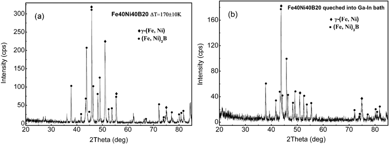
X-ray diffraction patterns of as solidified Fe40Ni40B20 alloy by a undercooling solidification and b rapid cooling solidification
Microstructure refinement in undercooling solidification
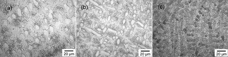
The typical cooling and heating curves for the solidification of Fe40Ni40B20 alloys with different ΔT are shown in Fig. 2. The highest ΔT up to 220±10 K was achieved in the undercooling experiments. Two kinds of microstructure refinement take place with increasing ΔT. From Fig. 3a and b, the primary γ-(Fe, Ni) dendrite and lamellar eutectic γ-(Fe,Ni)/(Fe,Ni)3B are significantly broken and refined for ΔT from 0 to 65 K. The first microstructure refinement occurs at ΔT∼65 K. For ΔT = 80–120 K, the as solidified microstructures are almost occupied by the primary dendrites (Fig. 3c and d). These dendrites are much coarser than those in Fig. 3b. However, with the increasing ΔT, the second microstructure refinement takes place for ΔT>143 K (Fig. 3e and f). After that, only anomalous eutectic and primary dendrites are observed (Fig. 3f). For even larger ΔT (>200±10 K), the anomalous eutectic is very fine, and the size of each phase in the eutectic is ∼2 μm (Fig. 4).
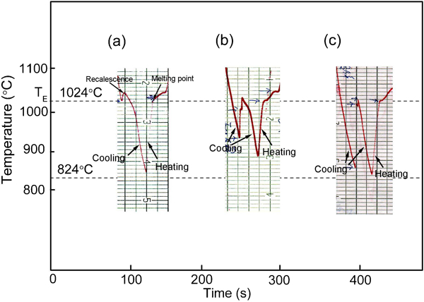
Typical cooling and heating curves of Fe40Ni40B20 alloy corresponding to different ΔT recorded by infrared pyrometer
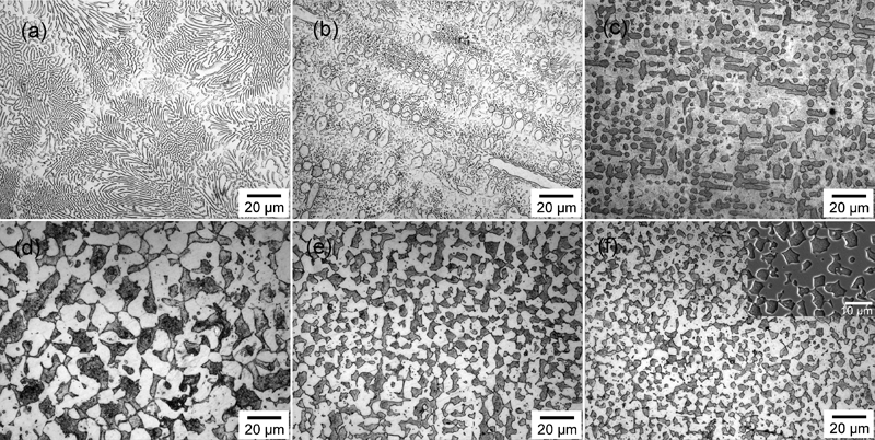
Microstructures of Fe40Ni40B20 alloy with a ΔT = 0 K, b ΔT = 65 K, c ΔT = 80 K, d ΔT = 123 K, e ΔT = 143 K and f ΔT = 181 K (optical microscope images); inset in f (SEM image) shows anomalous eutectic structures
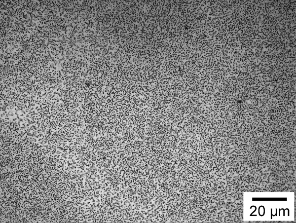
Anomalous eutectic structures in deep undercooled Fe40Ni40B20 alloys with ΔT = 220 K
Microstructure refinement under different cooling conditions
In these experiments, Fe40Ni40B20 melts with ΔT≈50 K are solidified under different cooling conditions. The microstructures obtained by natural cooling, water quenching along with the crucible and direct water quenching are shown in Fig. 5a–c respectively. One can see that the microstructures are refined gradually with an increasing cooling rate. Meanwhile, the remelting and fragmentation of the dendrite weaken.
Microstructures for Fe40Ni40B20 alloys with ΔT≈50 K subjected to different cooling conditions
The microstructure from iron plate cooling is shown in Fig. 6. It is composed of dendrites at the edge of the sample (Fig. 6a) and lamellar eutectic cells in the middle of the sample (Fig. 6b). The similar microstructure is obtained by Ga–In alloy bath cooling, but they are very fine (Fig. 7). The eutectic cells in the middle of the sample are ∼5 μm in diameter (Fig. 7c). Particularly, the spacing of the eutectic lamellae is <100 nm, which means nanostructure eutectic has been achieved by this method.
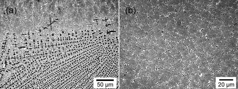
Microstructures for Fe40Ni40B20 alloys with ΔT≈50 K subjected to iron plate cooling
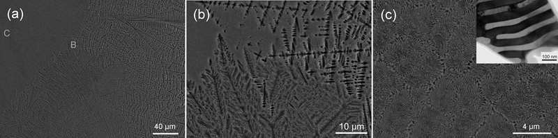
Images (SEM) of Fe40Ni40B20 microstructure obtained by Ga–In alloy bath cooling; magnified images of regions marked by capital letters in a are shown in b and c, b dendrite and c lamellar eutectic cells; inset in c is TEM image of lamellar eutectic cell with spacing of lamellae <100 nm
The as spun microstructure from the overheated melt is also shown in Fig. 8. The corresponding X-ray diffraction patterns are given in Fig. 9. From Figs. 8 and 9, it is found that the amorphous structure, along with dispersed large dendrites, appears at rS = 2500 rev min−1 (with a ribbon thickness h of ∼50 μm), and a totally amorphous structure is obtained when rS>5000 rev min−1 (with h≈20 μm).
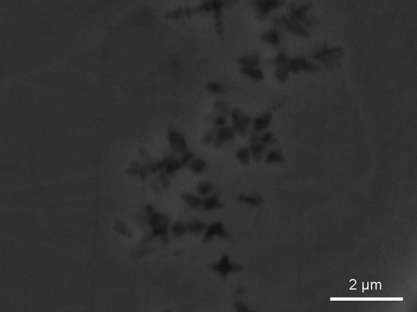
Image (SEM) from cross-section of Fe40Ni40B20 melt spun ribbons obtained at rotation speed of 2500 rev min−1: some dispersed dendrites are shown
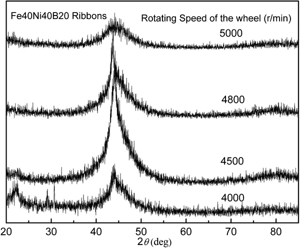
X-ray diffraction patterns for as solidified Fe40Ni40B20 ribbons obtained by melt spinning method at different rotation speeds
Discussion
The microstructure formation in non-equilibrium solidification of Fe40Ni40B20 alloys is determined by two successive courses: the nucleation and growth of the solid phase as well as the structural change after the primary solidification (e.g. remelting and fragmentation of the primarily formed solid phase).
Microstructure refinement in undercooling solidification
In the present undercooling experiments, two kinds of microstructure refinement take place with increasing ΔT. It is mainly a result of the fragmentation of the primarily formed solid phase during recalescence. The dendrite fragmentation by remelting can be predicted by comparing the characteristic time of dendrite break-up and the time for the interdendritic melt to be completely solidified (i.e. the plateau duration for recalescence).4 The plateau duration is exclusively controlled by the heat transfer from the sample to the environment and can be varied by changing the cooling rate.4 The characteristic time of dendrite break-up depends on the undercooling. It changes non-monotonously with increasing undercooling.4 Therefore, under certain cooling conditions, twice remelting can be predicted in undercooled solidification of many single phase alloys by comparing the two characteristic times.6–9 In binary alloys Ni–Cu,6 Fe–Ni,7 Fe–Co8 and Co–Pd,9 the experimental measured undercooling intervals for first microstructure refinement by single phase dendrite remelting are 27–84, 22–80, 22–83 and 72–95 K respectively. They are compatible with the predicted values calculated by the dendrite fragmentation model.4 At large undercoolings, the stresses caused by solidification shrinkage and fluid flow also favour the fragmentation of the microstructure.6,9 The dendrite fragmentation due to both remelting and high stress together causes microstructure refinement.6,9 The corresponding critical undercoolings are 180, 140, 183 and 142 K for Ni–Cu,6 Fe–Ni,7 Fe–Co8 and Co–Pd9 alloys respectively.
In ternary eutectic Fe40Ni40B20 alloys, the primary dendrites and the eutectic structures occupy the final microstructures. The microstructure refinement at low undercooling is similar to that in single phase alloys and due to the primary dendrite remelting. This can also be predicted using the dendrite break-up model,4 but the calculating result is unavailable here for the lack of model parameters of the FeNiB ternary alloy. The experimental obtained undercooling interval for the first refinement is below 65 K. It is comparable with those of binary alloys. It should be noticed, in ternary eutectic alloys, that the primary dendrite break-up is just one cause of microstructure refinement. There are two phases in the microstructure, and the remelting and fragmentation of a regular eutectic phase into an anomalous eutectic are also reasons for refinement. At large undercoolings, the high stress produced during the rapid solidification could also lead to the break-up of the primarily formed structures and cause the second refinement. The corresponding undercooling is ∼140 K in the present case. The critical undercooling is also comparable with those of binary alloys. Moreover, for a ternary eutectic alloy, the plateau time for recalescence is much longer than that for a single phase alloy due to the slower eutectic formation after the primary dendrite growth. Thus, the remelting is more obvious, and there is no integrated dendrite in the undercooling experiments.
Microstructure refinement in rapid cooling solidification
Similar to those in undercooling experiments, the microstructure refinements in rapid cooling solidification are mainly the result of structure fragmentation of the primarily formed solid phase when the cooling rate is not very high. Whereas, at the high cooling rates, some other causes are dominating the microstructure formation. The reasons will be given in the following section. First, some characteristic parameters are defined as follows: the temperature for the beginning of recalescence TN, the liquidus and solidus temperatures TL and TS, the maximum recalescence temperature TR and the recalescence height ΔTR (ΔTR = TR−TN = TR+ΔT−TL).
In the solidification, the morphologies of the as obtained microstructure are largely influenced by TR, which is related to both heat production and heat transfer during recalescence. TR can be obtained from the energy conservation law as20
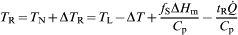
 is the heat extraction rate per unit volume, which is related to the contact area between the cooling mediums and melts and the heat conductivity of the cooling mediums.
For Fe40Ni40B20 melts with the same ΔT, the obtained TR will be different subject to different cooling conditions (i.e. different  ) according to equation (1). At the smaller cooling rate, because the latent heat cannot be transferred to the surroundings immediately, the relatively larger TR will be achieved, which leads to the remarkable remelting and fragmentation of the microstructure. With the increasing cooling rate, the remelting and fragmentation weaken due to decreased TR. This is consistent with the experimental observation. Only dendrite fragments and/or anomalous eutectics caused by remelting and fragmentation are found in the microstructure by natural cooling or water cooling (Fig. 5). However, the microstructure obtained at very high cooling rates contains well developed dendrites and eutectics with no evidence of remelting or fragmentation (Figs. 6 and 7). Moreover, as mentioned in the above section, the plateau duration of recalescence is exclusively controlled by the heat transfer from the sample to the environment. At a certain undercooling, the plateau duration decreases monotonously with increasing cooling rate.4 According to the fragmentation model,4 in rapid cooling conditions, the high heat transfer rate will lead to a short plateau duration and, thus, a weak fragmentation by remelting.
Nanostructure formation: Combination effects of undercooling and rapid cooling
In all the experimental results, it is worth noting that the eutectic cells with nanostructure have been in formation in the FeNiB alloy with ΔT≈50 K subjected to Ga–In alloy bath cooling. There are three possible mechanisms for the formation of nanostructure in as solidified microstructures: the spinodal decomposition of liquid leads to the final nanostructure solid phase; the decomposition of or precipitation from the primarily formed metastable phases gives birth to the nanostructure; and the nanosized grain solidifies directly from the melts due to the high nucleation rates and low growth rates at a certain condition. In the present case, the nanostructure eutectic is a result of the proper nucleation and growth rates due to the combination effects of undercooling and rapid cooling.
As is known, both nucleation and growth of the crystal phase during solidification are thermal activation processes. The energy barrier of growth is mainly the activation energy for atoms to cross the solid/liquid interface; thus, it is generally smaller than that for nucleation, which consists of the interfacial energy of the nuclei and the activation energy for atom movement. Therefore, in most cases, the nucleation rate has a maximum at the lower temperature T (the larger ΔT) compared with the growth rate.21 The typical curves for T dependence of the nucleation rate I and the growth rate V are plotted in Fig. 10. The temperatures  and
and  , which correspond to the maximum I and V, are not equal. This makes it possible to control the as solidified microstructure by different combinations of I and V, which can be fulfilled by changing the cooling rate or the temperature. In Fig. 10, if the melt temperature T is equal to T1, I is large while V is relatively small, a fine as solidified microstructure could be formed. If T is equal to T2, both I and V are very small; thus, an amorphous structure could be obtained.

Typical curves for temperature dependence of crystal nucleation (solid line) and growth rates (dashed line):
and  correspond to maximum I and V respectively
In the case of Ga–In alloy bath cooling with ΔT≈50 K, heterogeneous nucleation occurs at the surface of the sample where a large amount of heterogeneous nucleation sites exist. The primary dendrites originate from these sites and grow directionally toward the centre of the sample due to directional heat transfer (Fig. 7a and b). Meanwhile, as a result of undercooling in the melts, a large amount of eutectic cells nucleate (Fig. 7c). These eutectic cells originate from individual heterogeneous nucleation events.22,23 As discussed in the above section, at a high cooling rate, the remelting of the as solidified structure will not happen. Therefore, the regular lamellar structure is kept, i.e. regular lamellar growth proceeds in the eutectic cells. Moreover, the melt undercooling and the high cooling rate together lead to a high growth rate of eutectic lamellae. According to the models for the growth of regular eutectic,24,25 the spacing between the lamellae is inversely proportional to the square root of the growth rate. The lamella in the eutectic cell is therefore very thin. A huge number of eutectic cells solidify simultaneously and quickly grow into the surrounding melts and touch each other. There is no spacing or remaining melts left for them to grow to a large size. They have a small size at last. All these factors lead to the final small eutectic cells with nanostructure in them. However, in the as spun sample, only an amorphous structure with a few large dendrites in it, rather than nanostructure, is found. The reason is the suppression of the nucleation of the crystal phase from overheated melts subjected to very rapid cooling.
Experimentally, the nanostructure cannot be prepared by either undercooling method or rapid cooling method alone for the Fe40Ni40B20 alloy. By a combination of melt undercooling with rapid cooling, the nanostructure can be obtained. On the one hand, a large nucleation rate can be attained by undercooling. On the other hand, rapid cooling leads to quick heat extraction, which maintains the regular lamellar eutectic growth with a proper growth rate. These two factors lead to a large amount of nuclei growing slowly during the subsequent solidification and the formation of nanostructure.
Conclusions
The microstructure refinement of Fe40Ni40B20 alloy in undercooling and rapid cooling solidification has been investigated. The microstructure formation is determined by two successive courses, i.e. the primary nucleation and growth of the solid phase as well as the subsequent structural change (i.e. remelting and fragmentation of the primarily solidified microstructure). One of them should play the predominant role in determining the final microstructure under certain conditions. In undercooling solidification, two kinds of microstructure refinement have taken place with increasing undercooling. In rapid cooling solidification, the as solidified microstructure refines first and then coarsens with the increasing cooling rate.
The experimental results indicate that the nanostructure cannot be obtained either by the melts undercooling method or the rapid cooling solidification method alone. For the Fe40Ni40B20 alloy, small eutectic cells with nanostructure have been formed in the undercooled melts with ΔT≈50 K by Ga–In alloy bath cooling. This gives a potential approach to obtain bulk nanostructure materials: an appropriate primary undercooling ΔT combined with the proper subsequent cooling of the melts.
Footnotes
Acknowledgements
The authors are grateful for the financial support of the Free Research Fund of State Key Lab of Solidification Processing (grant nos. 09-QZ-2008 and 24-TZ-2009), the 111 project (project no. B08040), the Natural Science Foundation of China (grant nos. 51071127 and 50901059), the Huo Yingdong Young Teacher Fund (grant no. 111502) and the National Basic Research Program of China (973 Program) under grant no. 2011CB610403.