
Abstract
During micro-/nanoindentation, sharp deformation gradients are developing in the neighbourhood of the indenter's tip. These gradients should be taken into account in interpreting related measurements of hardness versus indentation characteristics, such as penetration depth, contact radius and plastic zone size. One way to do this is to resort to mechanism based dislocation arguments by utilising, for example, Ashby's concept of geometrically necessary dislocations, the density of which is directly related to plastic strain gradients, as shown by Nix and Gao. Another mechanics based approach is to utilise a gradient plasticity formulation, for example, the one advanced by Aifantis and co-workers, which, in conjunction with Johnson's cavity model, seems to be more flexible in interpreting the indentation size effect (ISE). For very small indentation depths, plastic flow does not occur until the equivalent strain, in the gradient elasticity (GE) region surrounding the hydrostatically pressurised core beneath the indenter's tip, reaches a critical yield value. In this latter case, the observed ISE effect is interpreted through GE considerations.
Introduction
Hardness is a characteristic material property defined and easily measured in various ways through impression or indentation tests but not easily interpreted or related to other standard material properties such as elastic modulus and yield stress. With the development of microindentation and (more recently) nanoindentation techniques, it became possible to easily observe and measure scale dependent mechanical characteristics by varying the size and shape of the indenter tip as well as the penetration depth. However, a rigorous theoretical mechanics description of the hardness test is quite difficult, as it requires the solution of a complex boundary value problem in elasticity (for very small indentation depths) and plasticity (for moderate or large penetration depths).
One outstanding feature common to all indentation processes is the development of sharp strain gradients near the indenter tip, especially for small to moderate indentation depths. Another related feature is the indentation size effect (ISE), i.e. the dependence of hardness on various indentation parameters such as penetration depth, contact radius and plastic zone size. Several approaches have been developed to interpret the various types of ISE observations. A neat and most interesting argument was outlined by Nix and Gao.
1
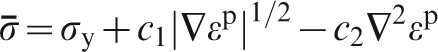
They utilised Ashby's concept of geometrically necessary dislocation (GND) density ρGND (ρGND∼▿γ; where ▿ denotes gradient, and γ denotes plastic strain) to bring into Taylor's expression for the flow stress [τ∼(ρs+ρGND)1/2; ρs is the density of statistically stored dislocations] the aforementioned strain gradient dependence and use subsequently Tabor's empirical rule to relate yield stress to hardness. As a result, the ISE pertaining to the dependence of hardness on indentation depth was modelled in good agreement with the experimental measurements. Another dislocation mechanism independent approach is to utilise the gradient plasticity (GP) framework of Aifantis and co-workers2–4 by employing a gradient dependent flow stress expression [τ∼(1+c1|▿γ|m+c2▿2γ), where m is a constant, while c1 and c2 are phenomenological gradient coefficients, which may depend on γ, accounting for strain gradient hardening or softening]. By properly adjusting m and the gradient coefficients (c1,c2) and by also approximating the gradients (▿γ,▿2γ) through macroscopic geometric parameters of the indentation process, it is possible to deduce the hardness dependence on indentation depth for various materials in agreement with experiments, as shown in Ref. 4. Again, Tabor's rule ( ) is used to connect yield stress σy to hardness H, a macroscopic rule which may not apply to micro-/nanoscales.
While the above described procedures provide convenient and easy to use relationships for the dependence of hardness on indentation depth, they are not suitable for giving any information on the relation of hardness to contact radius and plastic zone size developed in the region beneath the indenter's tip for moderate or large penetration depths. Such size dependent relations have been obtained experimentally, and it is shown in the present paper how they can be theoretically interpreted using a GP formulation to revisit Johnson's expanding cavity model. 5 This model assumes that beneath the indenter tip there is a material core region under hydrostatic pressure (identified with the hardness) embedded within a semispherical plastic zone where the material yields according to GP, while being constrained by the surrounding linearly elastic material region extended to infinity. With such simplifying assumption, the corresponding boundary value problem can be solved analytically to provide explicit size dependent expressions for the hardness in terms of plastic zone size and contact radius. These expressions (which are reduced to those derived by Johnson when the gradient coefficient or internal length is set equal to zero) compare well with the experiments and, thus, this procedure seems to be able to capture the ISE when plastic flow occurs under the indenter tip.
The ISE has also been observed for very small indentation depths, where massive plasticity is absent, and the deformation induced under the indenter's tip is elastic or nearly elastic. Again, size dependent relations for the hardness versus contact radius have been established experimentally, and it is shown here how these experimental measurements can be interpreted within the gradient elasticity (GE) formulation proposed by Aifantis and co-workers.6–9 To this end, it is assumed, as in the Johnson's expanding cavity model, that beneath the indenter's tip there is a material core region under hydrostatic pressure, surrounded by a gradient elastic material that is extended to infinity. The corresponding GE boundary value problem is solved to derive, among other things, hardness versus contact radius relations that compare well with the experiments. When the elastic internal length is set equal to zero, the resulting linear elasticity analysis and corresponding indentation relations are similar to that of Yoffe and co-workers. 10
The plan of the present paper is as follows. The section on ‘Hardness versus depth ISE effect’ considers the hardness versus indentation depth dependence through a simplified and approximate GP argument that does not require to solve a related boundary value problem. The derived hardness versus depth relations compare well with the experiments. The section on ‘Revisiting Johnson's expanding spherical cavity model’ revisits Johnson's expanding cavity model within a GP framework and derives relations for the dependence of hardness on the plastic zone size and the contact radius, which also compare well with available experimental results. Finally, the section on ‘Indentation size effect at small indentation depths’ considers very small indentation depths within a GE formulation of the respective indentation configuration providing, among other things, an analytical expression for the hardness versus contact radius, in agreement with experiments. It is emphasised that the approaches and results included herein should be considered only as preliminary and were presented in order to illustrate the potential of GE and GP to address unresolved issues of the indentation problem. It is hoped that these findings will stimulate additional and more detailed theoretical, experimental and numerical work along these lines.
Hardness versus depth ISE effect
A schematic representation of the basic geometric characteristics of a conical indenter penetrating into a plastically deforming substrate is illustrated in Fig. 1. 1 Approximate expressions for the gradient (▿ϵp) and Laplacian (▿2ϵp) of the plastic strain, in terms of the basic geometric characteristics of the indentation process (i.e. penetration depth h, contact radius a and indenter's angle θ) are given in the figure. It is noted that in this simplified configuration, a ‘pseudogradient’ approximation is adopted (in analogy to Ref. 1) in order to avoid introducing an extra parameter related to the actual plastic zone size, which requires the solution of a boundary value problem, as discussed in the next section. In the case that the plastic zone may be taken as a circular region, then the aforementioned extra parameter may be taken as a constant of proportionality providing the plastic zone size which should be used for estimating the plastic deformation quantities shown in the figure.
Schematics of indentation geometry: approximate expressions for gradient and Laplacian of plastic strain
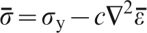
Next, we assume a gradient dependent yield condition of the form2–4

 ,
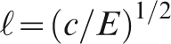
, ) denote the equivalent stress and plastic strain, σy denotes the yield stress and c is a gradient coefficient connected to the internal length
  through the relation
  . Finally, using Tabor's rule (
 ), we derive the following relation for the hardness H at depth h as a function of the microscopic hardness H0, the indenter's depth h and the internal length
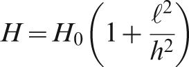
 = 213 nm is given in Fig. 2 for Cu.
11
It is concluded that this model overestimates the hardness for h>1000 nm and underestimates it for h<500 nm. It follows that in this ‘pseudogradient’ approach, the approximation of the Laplacian by the geometric parameters of the assumed idealised configuration for interpreting gradient hardening does not lead to desirable results. A much better fit is obtained by assuming a gradient dependent yield condition of the form
= 213 nm is given in Fig. 2 for Cu.
11
It is concluded that this model overestimates the hardness for h>1000 nm and underestimates it for h<500 nm. It follows that in this ‘pseudogradient’ approach, the approximation of the Laplacian by the geometric parameters of the assumed idealised configuration for interpreting gradient hardening does not lead to desirable results. A much better fit is obtained by assuming a gradient dependent yield condition of the form
 ) then yields
 ,
, ) are given by the expressions
 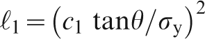 and
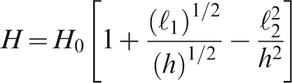
and 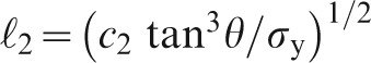 . Equation (4) is plotted in Fig. 3, where the comparison between model predictions (solid line) and experimental results (open circles) is shown. The values of the internal lengths
  and
and  were taken as
  = 274 nm and
  = 32 nm respectively. It should be noted that
  is related to macroscopic-like strain gradients acting over a characteristic length connected with the average grain size, while
  is related to microscopic-like gradients acting over a characteristic length related to dislocation arrangements within the grain. It is also interesting to note that this value of
  multiplying the Laplacian is comparable in magnitude with the corresponding value of internal length in the next section, where a boundary value problem is solved instead of using the ‘pseudogradient’ approach. In conclusion, in this section, it is pointed out that a connection between the phenomenological GP model given by equation (3) and dislocation based physical models may be established as follows. Let us write Taylor's expression for the flow stress as τ = As(ρs)1/2+AGND(ρGND)1/2, i.e. by adding a second term corresponding to the density of GNDs ρGND to the usual term containing the density of the statistically distributed dislocations ρs. It is noted that the relationship adding separately the square roots of ρs and ρGND rather than adding these quantities under the same square root symbol is more flexible as it allows for different premultiplication factors for ρs (connected directly to the plastic strain) and ρGND (connected directly to the plastic strain gradient). When ρGND<<ρs, the two different expressions for flow stress become equivalent on the basis of the approximation (1+x)1/2 = 1+x/2, where x = (ρs/ρGND)<<1. A more detailed elaboration pertaining to the proposed modification of Taylor's formula (which was also used in Ref. 7) by invoking arguments of dislocation cell formation and inhomogeneous evolution of internal stress will be the subject of a future discussion. By recalling that ρGND is proportional to the gradient of the plastic shear strain ▿γ, we can write the above relation as τ = As(ρs)1/2(1+A*|▿γ)1/2) or, in terms of the strain γ as τ = κ(γ)+c(γ)|▿γ|1/2, where we have formally set As(ρs)1/2 = κ(γ) and A*κ(γ) = c(γ). This argument justifies the c1 dependence in equation (3). The c2 dependence may be deduced by recalling
12
the relation between the average strain
multiplying the Laplacian is comparable in magnitude with the corresponding value of internal length in the next section, where a boundary value problem is solved instead of using the ‘pseudogradient’ approach. In conclusion, in this section, it is pointed out that a connection between the phenomenological GP model given by equation (3) and dislocation based physical models may be established as follows. Let us write Taylor's expression for the flow stress as τ = As(ρs)1/2+AGND(ρGND)1/2, i.e. by adding a second term corresponding to the density of GNDs ρGND to the usual term containing the density of the statistically distributed dislocations ρs. It is noted that the relationship adding separately the square roots of ρs and ρGND rather than adding these quantities under the same square root symbol is more flexible as it allows for different premultiplication factors for ρs (connected directly to the plastic strain) and ρGND (connected directly to the plastic strain gradient). When ρGND<<ρs, the two different expressions for flow stress become equivalent on the basis of the approximation (1+x)1/2 = 1+x/2, where x = (ρs/ρGND)<<1. A more detailed elaboration pertaining to the proposed modification of Taylor's formula (which was also used in Ref. 7) by invoking arguments of dislocation cell formation and inhomogeneous evolution of internal stress will be the subject of a future discussion. By recalling that ρGND is proportional to the gradient of the plastic shear strain ▿γ, we can write the above relation as τ = As(ρs)1/2(1+A*|▿γ)1/2) or, in terms of the strain γ as τ = κ(γ)+c(γ)|▿γ|1/2, where we have formally set As(ρs)1/2 = κ(γ) and A*κ(γ) = c(γ). This argument justifies the c1 dependence in equation (3). The c2 dependence may be deduced by recalling
12
the relation between the average strain  and the local strain γ, i.e.
 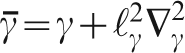 , where
  is a microstructure related internal length (proportional to grain size d for polycrystals). This relation can be inverted to read
 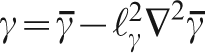 , which upon insertion to the above τ versus γ relation for the flow stress and linearisation can lead to equation (3) by redefining constants and relating
  to the macroscopic equivalent plastic strain
  .
.
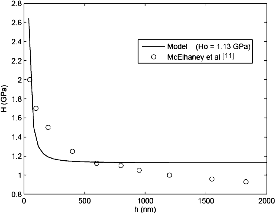
Hardness H versus indentation depth h as predicted by equation (2) and represented by solid line, in comparison with experimental results shown by open circles
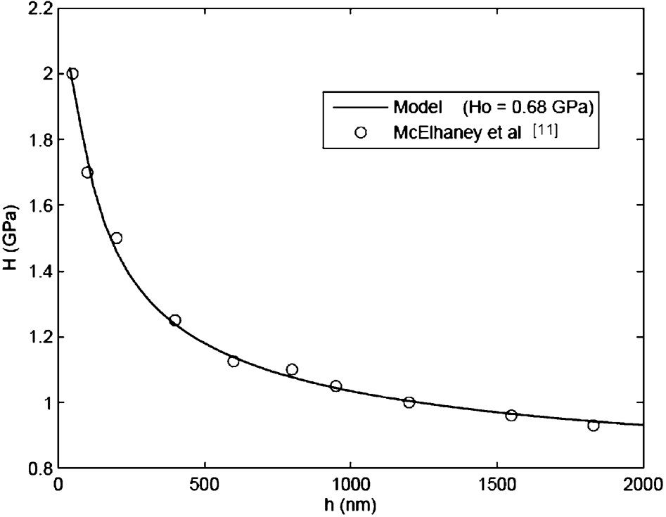
Hardness H versus depth h dependence according to equation (4) and comparison with experiment
Revisiting Johnson's expanding spherical cavity model
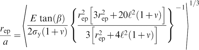
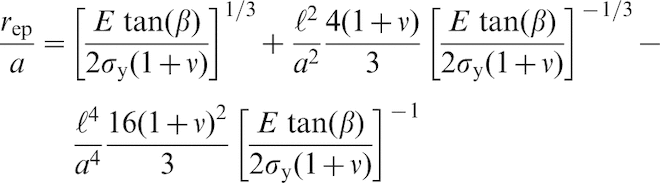
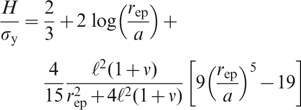
The schematics of Johnson's expanding cavity model is given in Fig. 4. It is assumed that the deformation state is same as for a spherical cavity of radius a embedded in an elastoplastic infinite medium. The plastic zone size is denoted by rep, and the material within it is deforming according to a gradient dependent yield condition of the form
 and equivalent plastic strain
  are given by
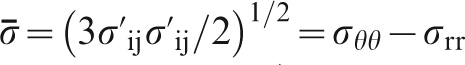 and
and  . The quantity
  denotes deviatoric stress, ϵij is the plastic strain tensor, (σrr,σθθ) are the spherical components of stress and ui is the displacement vector.
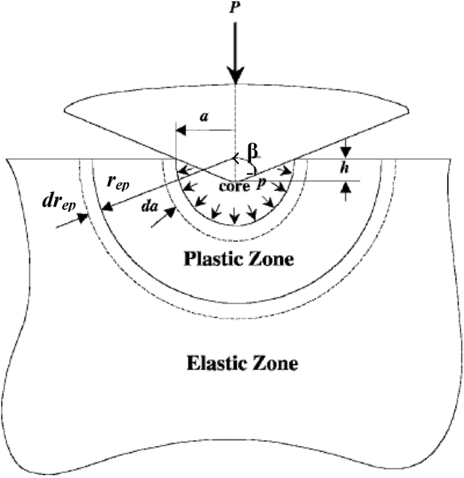
Schematic depiction of Johnson's spherical cavity model: core radius a, plastic zone radius rep and angle β between indenter's flank and free surface are shown
To proceed, we first consider the problem of a pressurised spherical cavity expanding in an infinite medium, as performed by Hill
13
for classical plasticity. This solution was used by Johnson
5
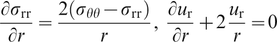
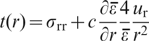
to develop his spherical cavity model, and thus, we will derive first its GP counterpart for use in the present modified size dependent formulation. The relevant equilibrium equation and incompressibility condition for the plastic region are given by

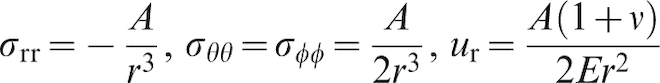
Next, we recall the form of the solution for the displacements and the stresses in the elastic region, which reads (E denotes Young's modulus, and ν denotes Poisson's ratio)
 was taken as
  16 nm in Fig. 5 and
  17 nm in Fig. 6. It is of interest to note that the internal length in this case, which corresponds to the internal length
  of the previous section multiplying the Laplacian of the plastic strain, is comparable in size to the internal length used in the approximate ‘pseudogradient’ analysis presented in that section. The fact that the ‘fits’ in the approximate analysis, as depicted in Fig. 3, seem to be better than the elaborate analysis based on the solution of the boundary value problem is due to the fact that in the first approach both the first gradient and the Laplacian of the plastic strain were used, while in the second, only the Laplacian of plastic strain was used, to dispense with additional complexities induced in the solution of the boundary value problem by including the first gradient as well in the expression for the yield condition.
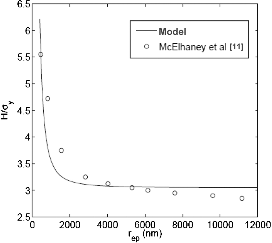
Comparison between model predictions (solid line) and experiment (open circles) for the variation of reduced hardness H/σy with respect to plastic zone size rep for Cu
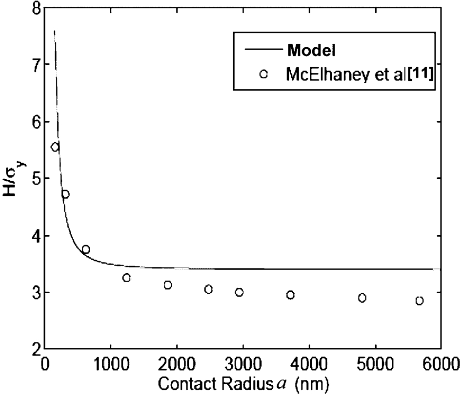
Comparison between model predictions (solid line) and experiment (open circles) for the variation of reduced hardness H/σy with respect to contact zone radius a for Cu
Indentation size effect at small indentation depths
In this section, we consider very small indentation depths before the material under the indenter's tip begins to yield through the emission of dislocation loops, as shown in Fig. 7. It should be noted that the illustration in this figure shows that dislocation loops nucleate at the indenter's tip. However, most workers in the field seem now to agree that the dislocations originate at some depth (about an indenter radius) below the indenter's tip, contrary to what is shown in the figure. However, this issue is not of concern here as it is related only to schematics and not to the model's mathematical development. This problem was considered by Yoffe and co-workers 10 within a linear elasticity framework. It is revisited here within a GE formulation in order to capture the ISE that has also been observed experimentally at very small depths, and thus, it may not be attributed to GP effects.
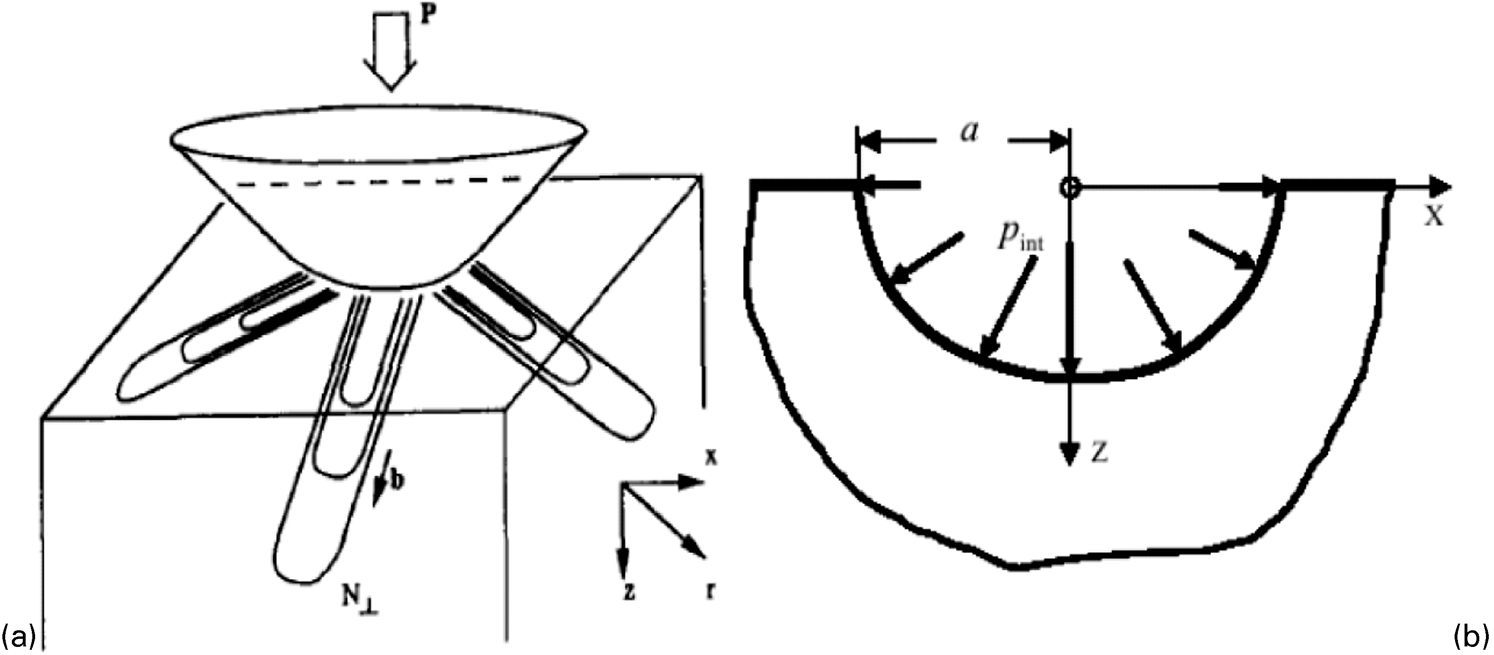
(a) dislocation loops emitted from indenter's tip at the onset of plastic deformation and (b) Yoffe's linear elasticity blister model revisited within the GE framework
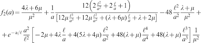
The pertinent GE solution is presented in Ref. 16, and we summarise below the main results. The displacement component in spherical coordinates is given by the relations
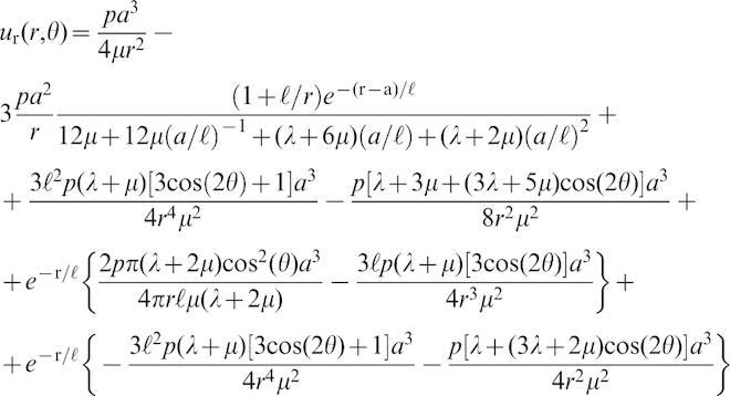
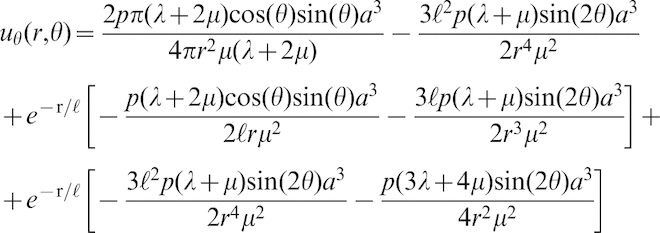
 is now given by the expression
  , and the GE constitutive equation is

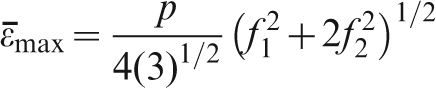
The equivalent strain 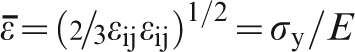 attains a maximum value given by the relation

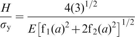
 was taken as
  = 90 nm. It should be noted that the fit in Fig. 8 is not satisfactory for large values of contact radius. This is expected as in this regime plastic flow becomes more pronounced, and the ‘small depth’ GE analysis provided herein may not be reasonable to apply. If, on the other hand, one roughly assumes that the presented GE analysis holds up to a critical contact radius of ∼70 nm after which massive plastic flow occurs, then a constant yield stress of perfect plasticity argument can be used to justify fitting the last two experimental points shown in the figure.
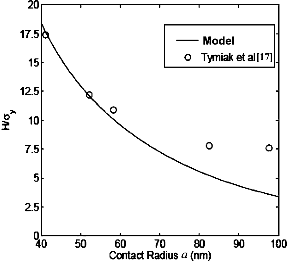
Variation of reduced hardness H/σy with respect to contact radius a for small indentation depths 17
Conclusions
The present paper analyses the ISE from the point of view of GP,2–4,6–7,12 as well as from the viewpoint of GE,6,8,9,15,16 as developed by the second author and his co-workers. The main feature is the introduction of first and/or second gradients in Hooke's law or in the yield condition along with corresponding multiplicative parameters c1 and c2 (gradient coefficients). These coefficients may be regarded as phenomenological internal length parameters, the values of which are determined by fitting available experimental results that cannot be interpreted by classical theory. In the case of plasticity, these gradient or internal length parameters related to internal microstructural features promote inhomogeneous plastic flow, and several microscopic models have been advanced in the above mentioned references to obtain specific expressions for them, depending on the prevailing microstructural configuration (dislocation cell size, grain size, interparticle spacing, etc.). It is noted, in this connection, that the origin of the internal length parameters is associated with the kinetic nature of dislocations and their transport in an inhomogeneously evolving internal stress field, which, among other things, gives rise to the Laplacian of plastic strain. Another type of phenomenological plasticity theory based on the concept of GNDs has been advanced in Refs. 18 and 19, and its application to interpreting the ISE was considered in Ref. 1. The two types of theories and their consistency with continuum thermodynamics have been considered recently in Ref. 20. However, a convincing physical substantiation for both types of the aforementioned phenomenological theories based on the underlying dislocation mechanisms is still lacking. A very interesting and in depth discussion, rooted in dislocation theory, has been provided in Ref. 21 concerning the relation between dislocation mechanisms and strain gradients along with corresponding implications to indentation and ISE. Incorporation of these arguments to the phenomenological theory of GP could bring new physical insight for the internal length parameters, but this is a subject for future considerations.
Footnotes
Acknowledgements
The authors are indebted to the reviewer for his sharp comments on an earlier version of the manuscript and to L. M. Brown for bringing to their attention some of his recent excellent work that they were not aware of.