
Abstract
In the present work, the process of equal channel angular pressing of dispersion strengthened Cu–1·1 wt-Al2O3 containing nanometric alumina particles was investigated by means of mathematical modelling and experimental testing. Through the modelling, deformation parameters such as hydrostatic pressure distribution and strain field were determined, and the effect of deformation path on these parameters was estimated. Equal channel angular pressing as well as mechanical and microstructural evaluations were also conducted to assess mechanical properties, grain structure and void volume fraction after deformation in different routes. The results indicate that distributions of plastic strain and hydrostatic stresses are significantly affected by deformation path route as well as utilised die design. Furthermore, void formation around hard alumina particles may occur in regions with high tensile hydrostatic stresses leading to fracturing during deformation.
Keywords
Introduction
Internally oxidised dilute solid solutions of copper alloys such as Cu–Al binary system have shown excellent thermal properties associated with considerable strength at a wide range of temperature, which make them appropriate materials for high temperature electrical and/or thermal applications.1 Accordingly, the knowledge on flow stress behaviour and mechanical responses of this material is of importance to produce a sound product in forming processes and/or to evaluate alloy performance under practical working conditions. In this regard, there have been limited works concentrating on the mechanical behaviour of Cu–Al2O3 systems during and after deformation processing. Kupcis et al.2 have studied particle size effect on tensile behaviour of internally oxidised single crystals Cu–Al with different volume fractions of Al2O3. Chopra and Niessen3 have investigated the influence of annealing temperature after cold tension and rolling on ductile fracture of Cu–Al–Ag internally oxidised composites. Besterci and Ivan4 have studied different failure mechanisms under uniaxial loading in Cu–5 vol.-Al2O3 composites produced by powder metallurgy techniques using in situ observation in an electron scanning microscope. Kucharova et al.5 have studied creep behaviour of Cu–Al2O3 composites at different temperatures, including low temperature creep between 673 and 773 K and high temperature creep in the range of 923–1023 K. Lee et al.6 have studied the relationship between the microstructures and the mechanical properties of Cu–Al2O3 system with nanometric alumina particles. They suggested that Orowan strengthening mechanism is responsible for the high yield strength of the alloy. Besterci et al.7 have investigated microstructures of Cu–Al2O3 dispersion strengthened materials with different Al2O3 contents in which the distribution of Al2O3 particles was determined and discussed. Guo et al.8 have conducted a research to assess tensile fracture mechanism and to determine the effect of predeformation on facture behaviour of Cu–Al2O3 composites.
On the other hand, equal channel angular pressing (ECAP) has recently been employed to improve and/or to modify microstructures as well as mechanical properties of deformable materials including composite materials.9 Accordingly, there are numerous works, both numerical and/or experimental studies, dealing with the deformation behaviour of various metals and alloy systems during and after ECAP.10–18 For instance, strain inhomogeneity during ECAP of pure aluminium and AA 6061 was evaluated by Xu and Langdon.10 Valiev et al.11 have evaluated the effect of severe plastic deformation via ECAP on mechanical properties and microstructures of AA 6061–10 vol.-Al2O3(p). Li and Langdon12 have studied grain size variations of AA 6061–10 vol.-Al2O3(p) during ECAP at room temperature up to total strain of 5. They found that considerable grain refinement can be archived; however, limited cracking of Al2O3 particles may occur. Dumoulin et al.13 have predicted strain distribution during one-pass ECAP employing a plane strain finite element formulation. Deng et al.14 have predicted texture development in ECAP of copper single crystal using crystal plasticity finite element approach. Figueiredo et al.15 have predicted strain distribution during two-pass ECAP ‘route C’ of copper regarding the effect of strain path change on flow stress behaviour of the deforming material. Dalla Torre et al.16 have studied microstructures and mechanical properties of copper in multipass ECAP processes. Paydar et al.17 have evaluated consolidation of aluminium particle in warm ECAP operations at 200°C. Sabirov et al.18 have studied and analysed the effect of multipass hot ECAP operations on particle distribution and of AA 6061–20 vol.-Al2O3 composites.
According to the published literature on material behaviour during ECAP processes, it can be found that there are limited works devoted to dual phase systems such as Cu–Al2O3 composites. Accordingly, in the present work, the deformation behaviour of dispersion strengthened Cu–1·1 wt-Al2O3 containing nanometric alumina particles during severe plastic deformation applied by cold ECAP is evaluated by means of a mathematical model performed in Abaqus/Explicit. Moreover, the effects of deformation path on the developed strain field and mechanical properties are investigated both theoretically and experimentally. To do so, ECAP experiments in different routes are conducted, and then, hardness and tensile tests together with scanning electron microscopy (SEM) are carried out on plastically deformed samples.
Model description
To determine the deformation pattern and strain fields during ECAP, a three-dimensional dynamic stress analysis based on updated Lagrangian formulation has been utilised in which linearly elastic hardening plastic material together with isotropic hardening rule was considered. In the model, the principle of minimum potential energy rate was employed as follows19
 ,
,
The above integrated model was then performed using Abaqus/Explicit.20 It is worth noting that eight-node isoparametric elements were utilised in the finite element analysis. After constructing the deformation model, mesh sensitivity analysis was carried out using the maximum pressure as the convergence criterion. Accordingly, the total numbers of 24 205 elements and 26 936 nodes were used to construct the meshing system, and a mass scaling factor of 100 was applied to reduce simulation processing time.
Experimental
Dispersion strengthened Cu–1·1 wt-Al2O3 with nanometric alumina particles was employed in the present research. The as received material was produced by inner oxidation method in which the atomised Cu–0·6 wt-Al powder with an average diameter of 100 μm was first oxidised in air at 900°C for 1 h and then followed by reduction in hydrogen atmosphere at 800°C for 1 h. In the next stage, the produced powder was compacted in a copper can under pressure of 500 MPa, and the can was heated up to 900°C in argon atmosphere; after 1 h of soaking time, it was extruded to a rod with a diameter of 18 mm. Finally, drawing operation as the final stage was performed to reduce the rod diameter to 14 mm. The as received rod was then cut into 100 mm samples, and they were deformed in an ECAP die with inner and outer corner angles Φ = 120° and ψ = 60° respectively. Single and double pass deformation routes were carried out, where in the double pass experiments, three different routes including routes ‘A’, ‘B’ and ‘C’ were used. It should be mentioned that the low workability of the employed alloy was the main limitation factor to carry out multipass ECAP operations, wherein in the third pass, the samples were broken into pieces. Thus, one- and two-pass ECAP experiments were only considered in the present work. After the deformation operation, tensile tests were performed on the equal channel angular pressed samples according to ASTM E8M. In addition to tensile tests, compression test was carried out on the sample with a height/diameter ratio of 1·5 to assess flow stress behaviour under compressive stresses and to be used as the input data in the mathematical model. Microhardness tests were also conducted using 100 g and holding time of 20 s in order to examine strain inhomogeneity developed within the deformed material. Furthermore, a sample was first annealed at 1000°C for 1 h and then subjected to tensile testing in order to evaluate the mechanical behaviour of the unstrained material. The alloy density was measured in different conditions, i.e. annealed, as received and deformed conditions, using buoyancy test in order to assess void volume fraction that could be produced during ECAP.
Microstructural evolutions using optical and SEM were also performed on the as received and equal channel angular pressed samples to illustrate the influence of deformation on the produced microstructures, while the solution of 2 g FeCl3, 2 mL HCl and 96 mL C2H6OH was utilised as the etchant. The grain size and void distribution within the as received and deformed specimens were then determined using an image analyser software, Clemex v3·5. Figure 1 shows the microstructures of the as received material by optical metallography and SEM. It is seen that a very fine grain structure is formed during the production stage where the grain structure is not possible to be revealed by regular optical metallography techniques as shown in Fig. 1a.
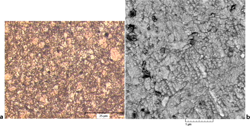
Microstructure of as received material
Results and discussion
In the first place, stress and strain distributions during ECAP were determined with the aid of the above mentioned model in which Young's modulus and Poisson's ratio were taken as 119 GPa and 0·34 respectively. It has earlier been established that strain distribution and final microstructure in multipass ECAP processes are influenced by the rotation of sample between successive passes so called processing routes.21 Accordingly, in the present work, three different routes of ‘A’, ‘B’ and ‘C’ were considered in the modelling. In route ‘A’, no rotation was applied between the first and the second pass, while in routes ‘B’ and ‘C’, the deformed samples after the first pass were rotated along their axis about 90 and 180° respectively. The model was run on a Core i7 processor with average run time duration of ∼72 h. In order to verify the predictions, the calculated and the experimental load–displacement diagrams during the first deformation pass were compared as shown in Fig. 2. It can be observed that there is a good agreement between the predicted and the recorded force–displacement data.
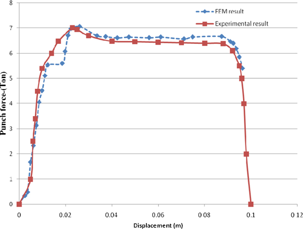
Predicted and experimentally measured load–displacement diagrams during first pass
The output of the model may now be employed to study the influence of path change on the strain and stress fields developed within the plastically deformed samples. For instance, Fig. 3 illustrates the distribution of equivalent plastic strain in the deformed specimens after two pass ECAP in routes ‘A’, ‘B’ and ‘C’, while in this figure, the regions that are in contact with the inner corner of the die channel in the first and the second passes are marked as regions’1’ and ‘2’ respectively. It can be seen that larger plastic strains are applied in the inner regions, and accordingly, the sample deformed in route ‘A’ experiences the highest strain inhomogeneity as compared to the other routes. Table 1 shows the maximum and the minimum equivalent plastic strains as well as the inhomogeneity factor and the measured average hardness of the deformed specimen in a cross-section plane after deformation in different routes. It is seen that the average amounts of equivalent plastic strains for all routes are almost the same, while the deviations between the maximum and the minimum plastic strains are somehow different. Generally, it can be concluded that route ‘C’ produces relatively more homogenous plastic strain distribution. It is worth noting that the achieved data are in agreement with the results of a work conducted by Tao et al.22 Furthermore, Fig. 4 shows the effective plastic strain distribution along the diameter of equal channel angular pressed rods from the outer region to the inner zone and variation of hardness in route ‘A’. The variations of the hardness and equivalent plastic strain for route ‘A’ are similar, and it implies that the results of the mathematical modelling are in proper consistency with those obtained by the experiments. In addition, this figure also shows that deformation in route ‘C’ produces a relatively uniform strain distribution compared to the other routes.
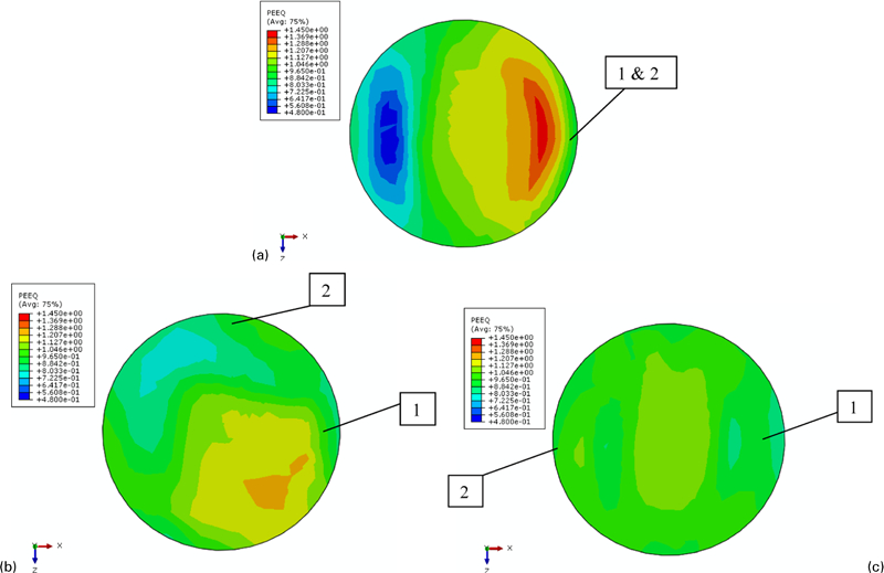
Distribution of equivalent plastic strain
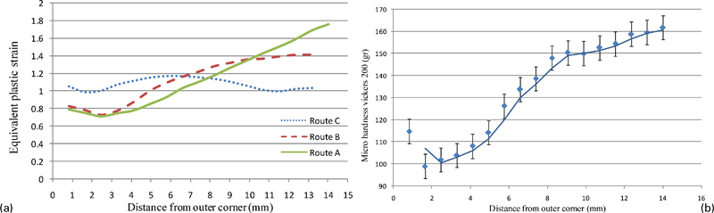
a equivalent plastic strain distribution of specimen after two-pass ECAP in different routes and b microhardness distribution produced within the sample deformed in route A
Predicted plastic strains, inhomogeneity factors and average hardnesses after different routes
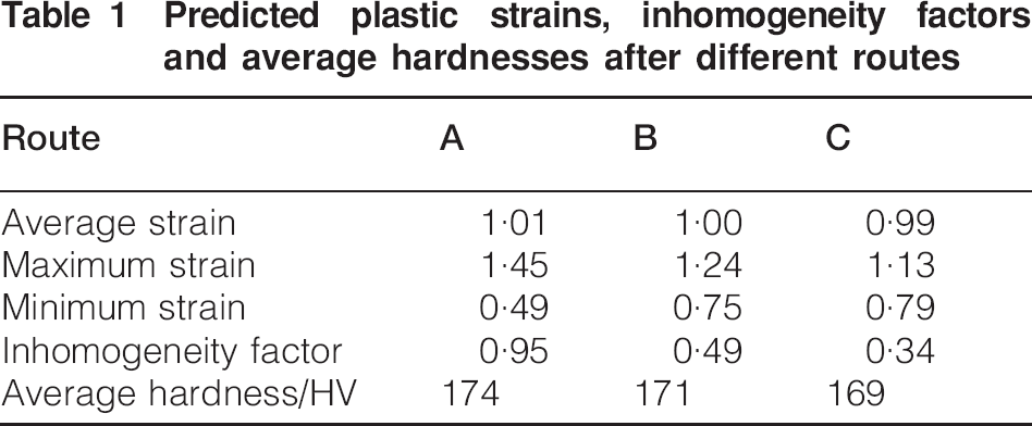
Figure 5 compares the grain structures after two-pass ECAP operations, and Fig. 6 and Table 2 show the distribution of grain size of the as received and the deformed samples obtained by the image analyser software in which >10 SEM images of different samples zone are captured and almost 5000 grain size data were employed for determining the grain size distribution. As can be seen, the grain structure after the deformation became finer and more uniformly distributed’ however, a more uniform grain structure was produced in route ‘C’. It is worth noting that the distribution of the grain size is consistent with the predicted equivalent plastic strain field.
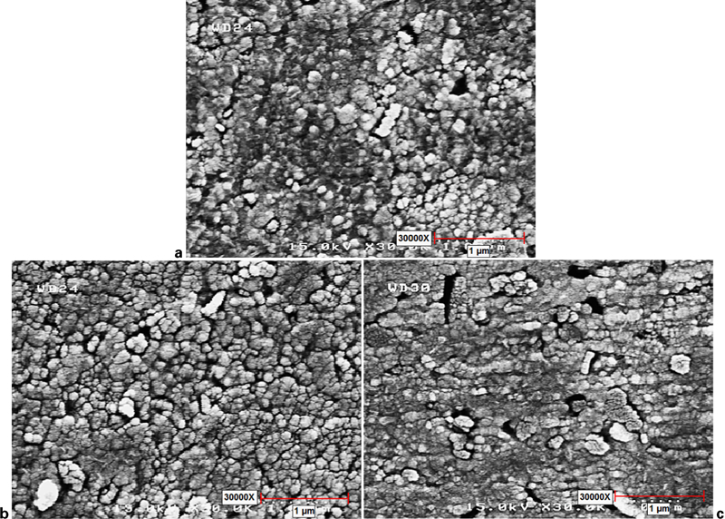
Images (SEM) of sample
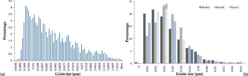
Grain size distribution of a as received material and b after two-pass ECAP
Mean grain of as received and deformed samples
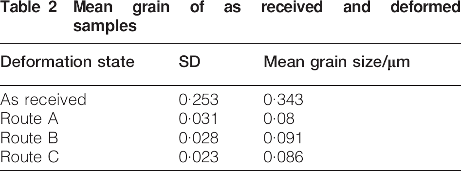
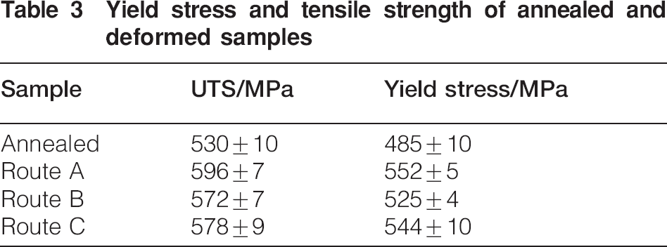
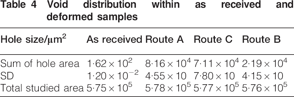
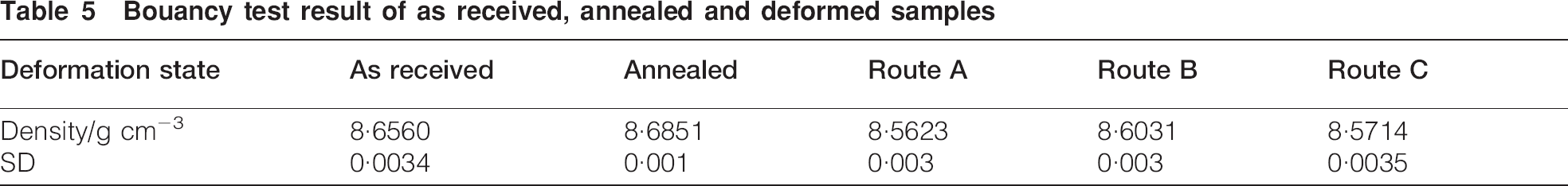
Figure 7 shows stress versus strain diagrams of equal channel angular pressed and annealed samples obtained by tensile testing, while measured yield stresses and tensile strengths are listed in Table 3. It can be seen that the deformation path has slightly changed the yield stress of the deformed alloy, which can be attributed to the distribution of plastic strain as well as the final microstructures, i.e. mean grain size of the equal channel angular pressed alloys and volume fraction of voids. On the other hand, the dispersion of alumina particles could influence the flow localisation while the tensile test is being carried out. It can be seen that two-pass ECAP has a lower impact on the ultimate tensile strength (UTS) as compared to the yield stress. It could be due to the formation of voids within the soft copper matrix during ECAP as shown in Fig. 8, in which the void volume fraction increases in the deformed samples. Table 4 shows the void distribution in different samples in which the image analysis was carried out almost through 0·58 mm2 of different regions of the samples. The results show higher void volume fraction using route ‘A’, which confirms the density measurements by buoyancy technique as illustrated in Table 5.
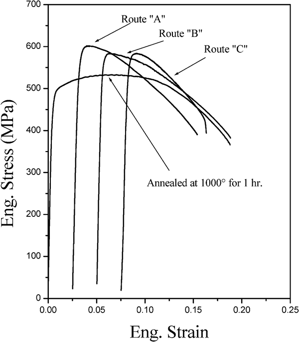
Stress–strain diagrams of annealed materials and deformed samples after different routes
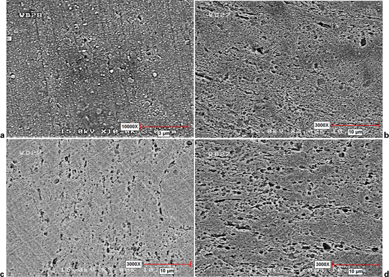
Images (SEM) of voids created in samples
Yield stress and tensile strength of annealed and deformed samples
Void distribution within as received and deformed samples
Bouancy test result of as received, annealed and deformed samples
It has been established that hydrostatic stresses have important influence on the workability of the deforming metal.23 One of the advantages of mathematical modelling of deformation processing is the estimation of such factors. Figure 9 displays the distribution of hydrostatic pressure during the second deformation pass in different routes. It can be seen that high tensile stresses are formed at the inner corner in all samples. This phenomenon may lead to the initiation of cracks and even fracturing of the deforming metal. This case in particular is important in the deformation of the Cu–Al2O3 system where the Al2O3 particles may provide suitable positions of void initiation and growth. Hence, the void formation promoted by hard alumina particles and tensile hydrostatic stress during ECAP could reduce the effect of plastic deformation on UTS, and even more, it might lead to fracturing during deformation. It should be mentioned that the highest void volume fraction is formed during deformation in route ‘A’ in two-pass ECAP operation.
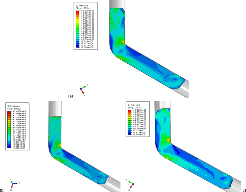
Distribution of hydrostatic pressure in the second pass
Increasing the void volume fraction during the deformation is obvious in Fig. 8, particularly around hard alumina particles. Therefore, the voids could be made by tensile hydrostatic stress together with the existence of hard alumina particles during deformation. Note that fracturing in some samples was also observed during ECAP experiments, where the fracture mostly occurred at the region in contact with the inner corner of the dies. Figure 10 shows the fractured sample in ECAP and the related hydrostatic stress distribution predicted by the model. It is seen that the fracture occurs at inner regions where high hydrostatic stresses exist based on the model predictions as shown in Fig. 9. In other words, workability of the alloy decreases owing to the presence of hard alumina particles together high hydrostatic stresses promoting nucleation and growth of cracks and voids during ECAP. Thus, the design of the die cavity would be of importance to control both the imposed plastic strains as well as the distribution of hydrostatic stresses during deformation in particular for the materials with lower workability.24
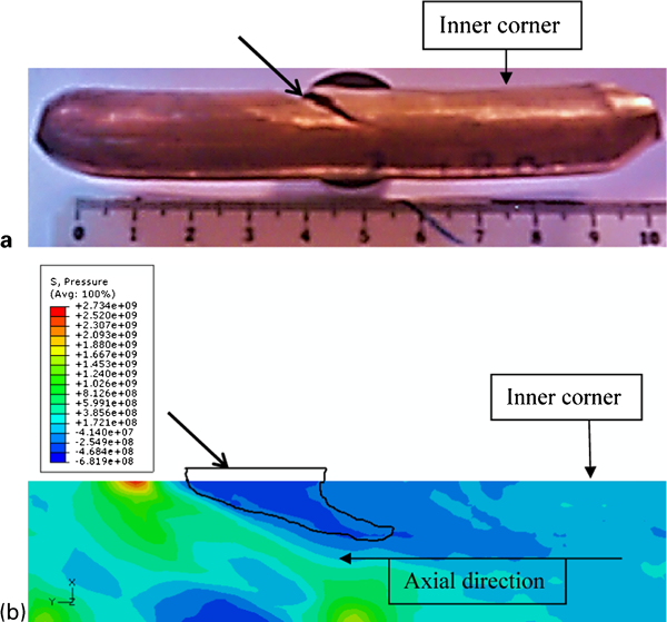
a fractured sample during deformation in route A and b predicted hydrostatic pressure during deformation
Figure 11 compares the developed effective plastic strain and hydrostatic pressure distributions using the dies with different angles of 120 and 135°. Regarding this figure, with a decrease in 15° in die angle, although the imposed plastic strain decreases ∼10, the hydrostatic pressure and its maximum value are reduced significantly in which the maximum tensile hydrostatic stress decreases from 375 to 202 MPa as the inner corner angle increases from 120 to 135°.
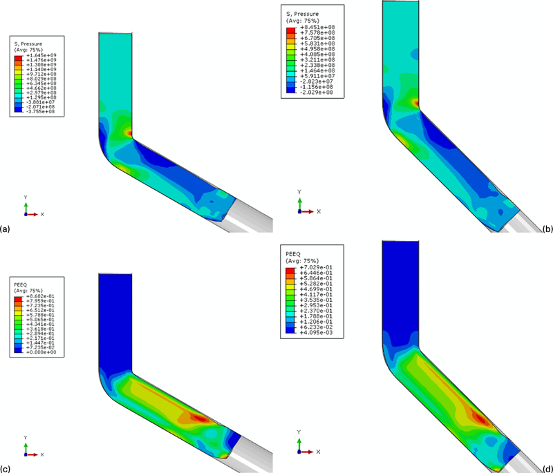
Distribution of hydrostatic pressure during pressing with die angles of a 120° and b 135° in first pass and effective plastic strain distribution during pressing with die angles of c 120° and d of 135° in first pass
Conclusions
In the present work, the ECAP of dispersion strengthened Cu–Al2O3 was investigated by means of experimental testing and mathematical modelling of the process. Three different deformation paths including routes ‘A’, ‘B’ ‘and ‘C’ were studied, and accordingly, the distribution of effective plastic strain, hydrostatic stresses, mechanical properties and developed grain structure were evaluated. The results show that the employed strain path can effectively change the distribution of plastic strain and hydrostatic stresses in which route ‘A’ produced the most inhomogeneous distributions. In addition, final mechanical properties were also influenced by the deformation path change. For the alloy system used in the present work, hard alumina particles associated with tensile hydrostatic stress could result in void formation within deforming samples, which decreases the UTS of the equal channel angular pressed product and/or fracturing during deformation. Based on the achieved data, it is suggested that deformation path ‘B’ and the inner angle of 120° or higher be employed in multipass ECAP operations to enhance cold workability of the material.