
Abstract
Wetting is the first and foremost event when a biomaterial is implanted into the biological system. Hence, it is very essential to investigate the wettability of a biomaterial before further biological studies. A textured coating with different relative amounts of Ca2SiO4 and CaTiO3 was in situ fabricated by varying laser scan speed. The wettability of different coatings was investigated. The results indicate that the relative amount of Ca2SiO4 phase increased with decreasing laser scan speeds and reached the highest value of 48·17±2·10 mJ mm−2, and the geometrically textured topography with a surface roughness of 9·17 μm was obtained at a laser scan speed of 2 mm s−1. The microstructure in the coating can be characterised as fine dendrites. Surface energy values varied with the relative amount of Ca2SiO4 phase. The coating obtained at the laser scan speed of 2 mm s−1, which contains more relative amount of Ca2SiO4, presents the highest surface energy, indicating most desirable wettability. This resulted in an increase in contact angle in simulated body fluid solution for improved wettability. The microhardness presented a gradient distribution from the coating surface (1072 HV) to the substrate (260 HV).
Introduction
To date, a significant amount of work has been performed on synthetic biomaterials due to their high demands for replacing damaged and degraded organs and tissues. An important group of these materials consists of so called bioactive glasses and ceramics. The main feature of these bioactive materials is the ability to produce a biologically active apatite called hydroxycarbonate apatite (HCA) layer on their surfaces in the human physiological environment. The HCA layer owns the phase that is similar to the mineral phase in bone, both chemically and structurally.1 This characteristic in turn provides a direct bond with living bone.
In the 1990s, many researchers and their co-workers2–5 reported that both wollastonite-2M (low temperature form of wollastonite) and pseudowollastonite (high temperature form of wollastonite) ceramics are bioactive and they also exhibit a faster formation of hydroxyapatite (HA)-like on CaSiO3 ceramics than that on other bioglass and glass ceramics in simulated body fluid (SBF). In recent years, investigators also found that dicalcium silicate (Ca2SiO4) has the potential to be used as biomaterials. Gou et al.6 investigated the physical and chemical properties of β-Ca2SiO4 pastes and revealed an enhanced proliferation response of fibroblasts, and this cement could also support adhesion and spreading of the mesenchymal stem cells, indicating an excellent bioactivity. Such a high bioactivity is attributed to the components of CaO–SiO2. Kokubo et al.7 and Ohtsuki et al.8 pointed that the CaO–SiO2 components contributed mainly to the bioactivity of these materials. Furthermore, Si is present at a level of 100 ppm in the bone and ligaments and 200–600 ppm in cartilage and other connective tissues.9 Moreover, silicon, together with calcium, sodium and phosphorus, acts on the expression of certain genes responsible for controlling the cell cycle of osteoblasts and stimulates osteoproduction.10 In addition, silicon tends to inhibit grain growth to generate materials with fine microstructures.11–13 Ceramic coatings such as wollastonite (CaSiO3), dicalcium silicate (Ca2SiO4) and diopside (CaMgSi2O6) have been regarded as the potential candidates for artificial bone.
However, due to the very brittle nature of several bioceramics such as bulk HA ceramics, it cannot be used in orthopaedic devices that must withstand substantial forces during their expected lifetimes.14 The problem can be solved by applying bioceramics or glasses onto metal substrates. The commonly used metals include titanium alloy and stainless steel. Several coating technologies, including plasma spray deposition,6 ion beam sputter deposition,15,16 chemical coating process,17 dip coating, electrophoretic deposition, sintering and flame spraying,18 have been introduced to obtain apatite/wollastonite glass–ceramic coatings and β-Ca2SiO4 coatings on titanium alloys, but they suffer from certain drawbacks such as poor adherence of the coating to the substrate material, lack of uniformity, absence of appropriate topographical cues at the surface and absence of desirable chemistry. These problems can be improved by laser ablation or laser in situ synthesising technology. The most common example of this technology is preparation of calcium phosphate coatings by laser cladding. In recent years, many works about preparation of calcium phosphate coating via laser cladding technology were developed.19–23 In addition, de Aza and his co-workers5,24 have reported the in vitro characterisation of laser ablation pseudowollastonite coating on titanium alloys. So far, seldom such researches as laser in situ synthesising of microtextured multiphase composite biocoatings and the wettability in SBF were reported.
To address these issues, in the present work, a highly intense laser beam was used to melt the precursor [x wt-CaO−(1−x) wt-SiO2] and the Ti–6Al–4V substrate. Laser is the preferred choice as it owns several advantages such as convenient operation, easy controlled heat affected zone and high efficiency.
The objectives of this paper are to in situ fabricate a microtextured Ca2SiO4/CaTiO3 composite biocoating; to investigate the phase constituents, topography, surface roughness and microhardness distribution; and to investigate the wettability of Ca2SiO4/CaTiO3 composite biocoating in SBF solution.
Experimental
Materials
Ti–6Al–4V (50×50×3 mm) was used as substrate coupons, which were cut from the rolled sheets. The cut coupons were then prepared for laser processing by initially polished using a silicon carbide emery paper to remove the oxide layer followed by rinsing with acetone. The precursor materials were 45 wt-CaO and 55 wt-SiO2 obtained from Shenyang Chemical Reagent Factory. The precursor was mixed in a water based organic solvent polyvinyl alcohol. The mixed slurry was then precoated onto the clean substrate coupons using an air pressurised spray gun. The sprayed coupons were then air dried to remove the moisture. The thickness of 150 μm of the precoating was maintained for all samples.
Laser cladding process
The laser induced in situ synthesising was carried out by scanning the sprayed coupons using a 500 W power, JHM-1GY-400 model pulsed Nd3+:YAG laser with a wavelength of 1064 nm laser. The laser control panel allows the control of pulse width, pulse repetition rate and pulse height. The lens assembly is equipped with a 75 mm focal length convex lens, which gives a spot diameter of ∼0·3 mm at focus. The focused spot was kept at ∼10 mm above the surface of the sample so as to have a spot size of ∼0·5 mm on the surface. The processing parameters used for the laser in situ synthesising process are listed in Table 1. From Table 1, it can be observed that the laser scan speed was varied, while the rest of the parameters were being kept constant.
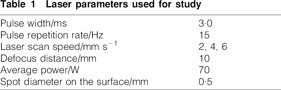
Laser parameters used for study
Wetting studies in SBF
Contact angle measurements were conducted by a static sessile drop technique using a CAM-Plus contact angle goniometer (Experimental Instrument Factory of HARKE, Beijing, China) equipped with video camera for imaging. For the calculations of surface energy, an apolar liquid (dioiodomethane) and two polar liquids (distilled water and formamide) were used. In order to correlate the surface energy calculations to the mineralisation behaviours of the samples, contact angles between the samples and SBF solution were measured based on baseline method. The SBF solution has the similar ionic compositions to that of the human plasma. It contains the following components: NaCl (8·026 g), NaHCO3 (0·352 g), KCl (0·225 g), K2HPO4.3H2O (0·230 g), MgCl2.6H2O (0·311 g), CaCl2 (0·293 g) and Na2SO4 (0·072 g) into distilled water (700 mL). The fluid then buffered to pH 7·4 at 37°C with tritydroxymethylaminomethane (TRIS, 6·063 g) and hydrochloric acid (1M, 40 mL). The surface energy components of different samples were calculated according to van Oss et al.'s approach25 using the following equations


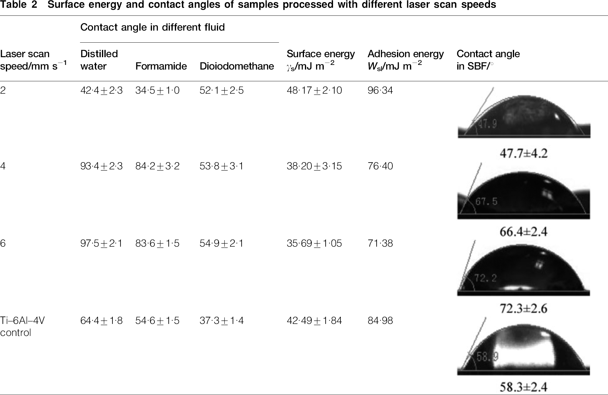
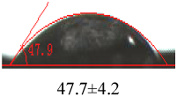
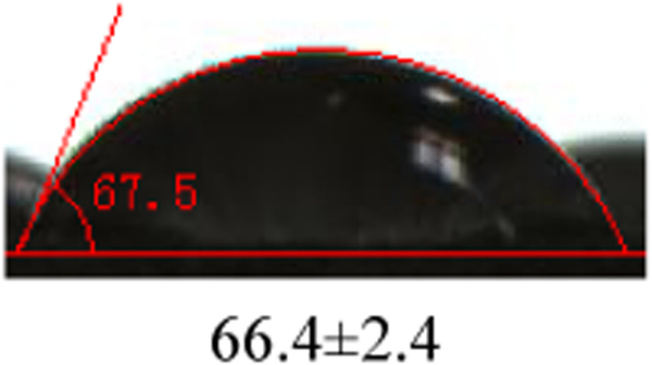
Surface energy and contact angles of samples processed with different laser scan speeds
Characterisation techniques
A Rigaku-D/MAX-A X-ray diffractometer system was employed to analyse the phase structure of the laser in situ synthesised coatings. The radiation source was Cu Kα radiation (wavelength, 0·15406 nm), which was operated at 30 kV and 20 mA. The 2θ angle ranged from 20 to 90°.
The laser processed samples were then sectioned perpendicular to the laser track using a low speed saw, and then polished and etched with etchant (10 mL HF, 30 mL HNO3 and 60 mL H2O) for optical microscope (OM) investigation, scanning electronic microscope (SEM) investigation and microhardness measurement. The structure of the coating was observed by means of SEM (SSX-550, Japan) instrument, which was operated at a volt of 15 kV.
The topography images and the three-dimensional images of the laser synthesised coatings were investigated using an Olympus-TY8648 laser scanning confocal microscope (LSCM). The surface roughness was measured six times for each sample to get the average value and evaluate the morphology of the coatings.
The 401 MVD (Olympus Corp.) Vicker's tester was employed to determine the hardness distribution and estimate the thickness of the coatings on metallographic cross-sections at room temperature. A normal load of 1·96 N was applied for 10 s for each sample. The microhardness was measured three times for each zone to get the average value.
Results and discussion
Phase evaluation
Phase characterisation of both precursor powders (mixture of CaO and SiO2) and precursor coated samples processed with laser scan speed of 6, 4 and 2 mm s−1 was carried out. Figure 1 (spectrum A) shows the X-ray diffraction (XRD) spectra of the precursor powder (mixture of CaO and SiO2). From the spectra, it can be seen that there are only peaks corresponding to CaO and SiO2, and the peaks are narrow and sharp, indicating that the mixture of CaO and SiO2 has high crystallinity. Spectra B, C and D represent the XRD studies for the samples processed with different laser scan speeds of 6, 4 and 2 mm s−1 respectively. Compared to the original precursor powders, no peaks corresponding to original powder (CaO and SiO2) phase was observed, demonstrating that no toxic CaO powder from the precursor material remained into the coating. On the contrary, some new phases including Ca2SiO4 and CaTiO3 were detected. Surprisingly, no major difference was observed in the types of phases with varying laser scan speeds (Fig. 1, spectra B–D). However, the total peak intensities corresponding to Ca2SiO4 and CaTiO3 are relatively weak for the sample processed with laser scan speed of 6 mm s−1. Thus, it appeared that at lower range of laser scan, the phase constituent is desirable.
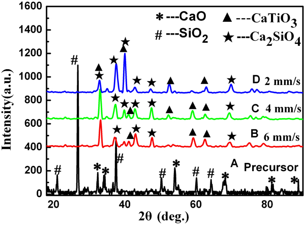
X-ray diffraction patterns of precursor and laser processed coatings
The formation of CaTiO3 and Ca2SiO4 can be explained on the basis of thermodynamics theory of the following possible primary and intermediate chemical reactions among the materials systems employed in the present works. Gibbs free energy principle was used to estimate the possibility of each reaction. The Gibbs free energy ΔG for each reaction calculated at the temperature of 2000 K, which approaches the laser melt pool temperature, was marked in the following reactions


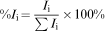
The relative amount of each phase was semiquantitatively conducted using the following formula26
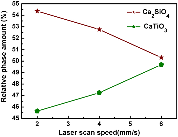
Relative phase amount as function of laser scan speed
Morphology, microstructure and microhardness
From the results of phase evaluation, it was concluded that a lower laser scan speed is desirable for obtaining Ca2SiO4/CaTiO3 composite coating. Hence, the OM and SEM images were only conducted for the sample processed with laser scan speed of 2 mm s−1 and presented in Fig. 3a–c respectively. The OM image (Fig. 3a) revealed that the coating with the thickness of ∼100 μm was obtained. A metallurgical bonding between the coating and the substrate was realised. Figure 3b represents the microstructure of the coating with a lower magnification. The detailed structure with a high magnification of the circled zone in the coating is presented in Fig. 3c. It can be seen that the microstructure of the coating can be characterised as fine dendrites with uniform distribution in the coating.
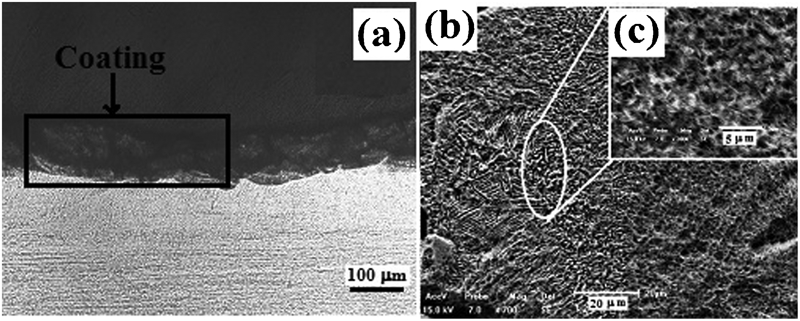
a OM image and b SEM image with lower magnification and c higher magnification of coating processed with laser scan speed of 2 mm s−1
The topography and the three-dimensional image of the coating surface obtained at the laser scan speed of 2 mm s−1 are investigated using LSCM and indicated in Fig. 4a and b respectively. Surface roughness measurements were carried out a few times at different locations to obtain average value. In Fig. 4, the geometrically textured topography is clearly visible with the regular pits. This is an indication of the formation of microscale features at the surface of the coating. The average value of surface roughness Ra is ∼9·165 μm, which is higher than that of the Ti–6Al–4V control (∼0·3 μm). The increase in the surface roughness can be attributed to the formation of such pits with microscale features. It was reported that such pits with microscale features can help toward numerous protein interactions and thereby aid cell orientation, alignment and finally tissue integration.27–31 Furthermore, these microscale features also mimic the extracellular matrix present in the body to support cells.27 A mechanical stimulation on the surrounding bone during the early days of implantation can be also induced by these pit topographies. It has been proved that the mechanical stimulation is provided by the improved shear strength at the interface and mechanical interlocking when the bone grows into these pits.32 Thus, the textured coating provides physical and chemical biocompatibility. The physical compatibility is provided through the textured surface that aids alignment and mechanical attachment of the cells, and various Ca and Ti based phases within the coating on the surface are likely to provide the chemical biocompatibility.33 Further works on the biocompatibility of Ca2SiO4/CaTiO3 composite coatings are now on the march, and the results will be presented in the following publications.
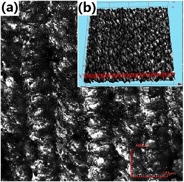
Images (LSCM) of coating processed with laser scan speed of 2 mm s−1 of a top view and b three-dimensional image of coating surface
Microhardness measurement is carried out on a typical sample processed with laser scan speed of 2 mm s−1 to ensure that the top surface is enriched with a ceramic based composition. Vickers hardness measurement along the cross-sectional plane transverse to the laser track from the coating surface to the substrate is presented in Fig. 5. A maximum hardness of 1070 HV0·2 was measured at the coating surface, and there is a gradient decrease in hardness toward the substrate. This indicates the existence of the ceramic based composition such as Ca2SiO4 and CaTiO3 at the top surface, which is in accordance with XRD results in Fig. 1. From Fig. 5, it also can be observed that the thickness of the coating is ∼130 μm.
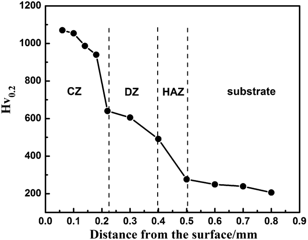
Microhardness distribution of sample processed with laser scan speed of 2 mm s−1
Effect of laser scan speed on wettability
Surface energy components (γ+, γ−, γLW and γs) were calculated from equations (1)–(3). The variation of these components as a function of laser scan speed is illustrated in Fig. 6. It is clear that the dispersive component (γLW) decreases with increasing laser scan speed and remains in the range of 39·7–47·8 mJ m−2. The basic polar component γ− follows a decreasing trend first and then increasing trend with increasing laser scan speed from 2 to 6 mm s−1. The acidic polar component γ+ has values <2·74 mJ m−2 and follows an increasing trend with increasing laser scan speed. The surface free energy γs presents an increasing trend with increasing laser scan speed. Compared to Ti–6Al–4V control (surface energy, 42·49±1·84 mJ m−2), the sample processed with laser scan speed of 2 mm s−1 presents higher surface free energy (48·17±2·10 mJ m−2), while the samples processed with laser scan speed of 4 and 6 mm s−1 present lower surface energy (38·20±3·15 and 35·69±1·05 mJ m−2 respectively). It indicates that a faster laser scan speed results in a lower surface energy. This can be attributed to the less relative amount of dicalcium silicate (Ca2SiO4) with increase in laser scan speed as shown in Fig. 2. It was reported that such a highly wetting silicate based phase forms at the grain boundaries34 and leads to more grain boundary groove formation. Less formation of dicalcium silicate may reduce the boundary groove formation. This in turn may have attributed to the decrease in surface free energy for increasing laser scan speed.
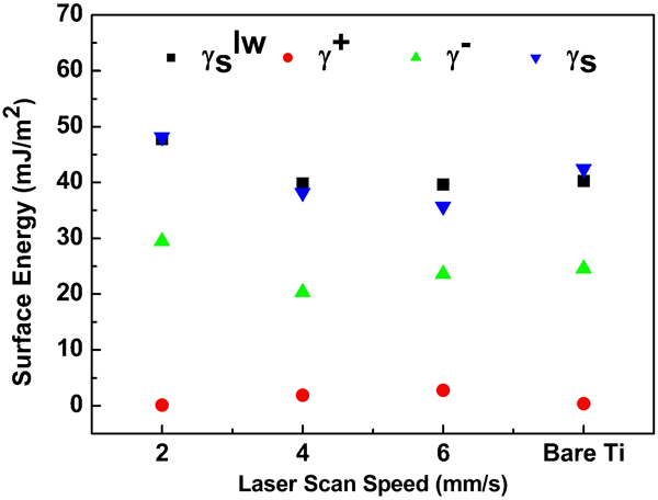
Surface energy components as function of laser scan speed
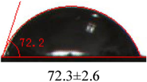
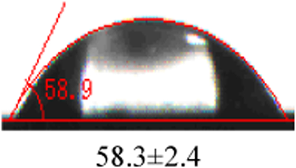
Wetting is the first and the foremost event when a biomaterial is implanted into the biological system. Hence, on the basis of surface free energy calculation, understanding the wettability with SBF and the effect of laser scan speed on the wetting behaviour were important in the present work and the future work on bioactivity and biocompatibility. Table 2 presents the contact angles and corresponding light optical images of SBF droplet shadow on laser processed samples with scan speed of 2–6 mm s−1 and the Ti–6Al–4V control. The contact angle presents an increasing trend with increasing of laser scan speed (Table 2). For Ti–6Al–4V control, the surface free energy is 42·49±1·84 mJ m−2, corresponding to contact angle in SBF of 58·9°. As for the sample processed with 2 mm s−1, the surface energy is higher than that of the control, corresponding to a smaller contact angle (47·9°) in SBF. Furthermore, compared to the sample processed with laser scan speed of 2 mm s−1, the samples processed with 4 and 6 mm s−1 present a less hydrophilic behaviour (lower surface free energy and bigger contact angle at the interface between SBF and samples). It can also be recognised that the contact angle decreases with decreasing laser scan speed for improved wettability. It is believed that the improvement of wettability for the sample processed with 2 mm s−1 results from microtexture and formation of more relative amount of new phase such as Ca2SiO4 in modified surface region.
The improved wetting behaviour can further be explained by adhesion energy, which is determined by the contact angle and calculated by rewriting Young's equation into the Young–Dupre’ equation35


Conclusions
In the present work, a geometrically textured Ca2SiO4/CaTiO3 composite biocoating with the thickness of 130 μm is in situ fabricated by laser processing CaO/SiO2 precursor. Surface coatings are performed with altering laser scan speed using a pulsed wave Nd:YAG laser. It has been observed that the constituents of the coating varied with laser scan speed. The relative amounts of Ca2SiO4 decrease while that of CaTiO3 increase with increasing laser scan speed. The coating zone shows a fine dendrite microstructure. The geometrically textured topography in the form of pits is obtained with a surface roughness of 9·17 μm corresponding to the sample processed with laser scan speed of 2 mm s−1. The surface roughness of the laser coated samples is much higher than that of Ti–6Al–4V control. The effects of laser scan speed on the wetting of the coating were examined. It was found that the surface energy values varied with the relative amount of Ca2SiO4 phase. The coating obtained at laser scan speed of 2 mm s−1, which contains more relative amount of Ca2SiO4, presents the highest surface energy, indicating most desirable wettability. This resulted in an increase in contact angle in SBF solution for improved wettability. The results indicate that the scan speed of 2 mm s−1 is desirable for obtaining a coating with more relative amount of Ca2SiO4 phase and in turn a higher wettability. The microhardness of the sample processed with laser scan speed of 2 mm s−1 presented a gradient distribution from the coating surface (1072 HV) to the substrate (260 HV).
Footnotes
Acknowledgements
Part of the present work is supported by the Fundamental Research Funds for the Central University under grant no. N100405001, Natural Science Foundation of China (NSFC) under project no. 50801012 and Natural Science Fund in Liaoning Province under grant no. 20102072.