
Abstract
Multiwalled carbon nanotube (MWCNT) reinforced copper matrix nanocomposites were fabricated by powder metallurgy technique, which consists of blending, compaction and sintering followed by hot forging technique. The microhardness of hot forged nanocomposites was evaluated and found to be higher than that of hot forged copper. The enhanced hardness was attributed to the hardening of the copper matrix by reinforcing effect of MWCNTs. Electron diffraction patterns obtained from MWCNTs and nanocomposites were indexed, and an orientation relationship was derived using stereographic projection. The orientation relationship between MWCNTs and copper appears to be [ ]fcc Cu||[
 ]MWCNT, and tube axis was found to be parallel to (3 1 1)Cu. However, no unique orientation relationship was observed between copper and MWCNTs.
Introduction
In the last few decades, metal matrix composites (MMCs) have found potential applications in high performance engines, military aircrafts, space structures and automotive industry owing to high strength, stiffness and exceptional dimensional stability. Metal matrix composites are reinforced with fibres, whiskers and particulates, which enhance the strength and stiffness of the metal matrix. However, the need for advanced composite materials with good thermal and mechanical properties combined with better tribological properties is ever increasing in the industries.1
Since their discovery, carbon nanotubes (CNTs) are being explored as a reinforcement for polymer, metals and ceramic matrices due to their extraordinary electrical, mechanical and thermal properties. The theoretical predictions show that CNTs possess elastic modulus in the range of 0·9–5·5 TPa, while experimental results confirm the same. The value of elastic modulus of CNTs is much higher than other rigid materials like carbon fibre (230 GPa) and SiC (414 GPa). The experiments conducted have resulted in tensile strength close to 63 GPa and is ∼10–100 times higher than that of steel.2–5 Using CNTs to reinforce in various metal matrices, the focus is on the development of advanced composite materials. Among the various metals, aluminium, copper, nickel and magnesium are more frequent as the matrix materials and are processed via powder metallurgy, spraying method and electrochemical deposition. The research group from Florida International University headed by Agarwal and his team has extensively worked on Al–Si alloy reinforced with CNTs by plasma, high velocity oxyfuel spray forming and cold spraying technique.6,7 Gupta and co-workers from the National University of Singapore have published a fair number of research articles on magnesium/CNT composites by melt deposition technique.8 Kim and co-workers have developed copper/CNT composites by molecular level mixing method followed by spark plasma sintering.9 Koppad et al.10 have developed multiwalled carbon nanotube (MWCNT)/Cu nanocomposites by powder metallurgy technique followed by hot forging. The obtained nanocomposites showed enhanced mechanical properties with the incorporation of both uncoated and nickel coated MWCNTs. The powder metallurgy technique remains the most popular and convenient method to fabricate the CNT reinforced MMCs.11,12
Various studies have shown marginal increase in the properties of CNT reinforced MMCs. This is mainly due to inhomogeneous dispersion and formation of undesirable reaction products at the interface of CNTs and metal matrix. The interfacial bond strength also plays a vital role in determining the effective load transfer from CNTs to metal matrix. The matrix materials like aluminium and copper do not wet on the surface CNTs, which is necessary for good interfacial bond strength.13
Electron diffraction (ED) is a powerful technique used for structural analysis of CNTs and provides deep insights into understanding of the atomic structure of various materials. In a review article, Amelinckx et al.14 have discussed the detailed studies on ED from CNTs. Most research works have focused on strengthening the various matrices by adding CNTs. Unfortunately, there is a limited published literature on the orientation relationship between CNTs and matrix material. According to Bakshi et al.,15 due to the difference in the structural configuration, no orientation relationship was observed between Al4C3 and CNTs in plasma sprayed CNT reinforced Al–Si composites.
In the present study, MWCNT reinforced copper matrix nanocomposites fabricated by powder metallurgy and hot forging technique were subjected to ED studies to get insight into orientation relationship of MWCNTs and copper matrix.
Experimental
Multiwalled CNTs (outer diameter, 20 nm; length, ∼1 μm; density, 2·1 g cm−3) synthesised by chemical vapour deposition and copper powder of ∼99·5 purity were used in the present study. Pure copper and different nanocomposite compositions with 1, 2, 3 and 4wt-MWCNTs were studied. The powder metallurgy process was adopted to synthesise the nanocomposites. The process begins with the preparation of powder mixture, in which MWCNTs along with copper powder were loaded in stainless steel vial and mechanically milled in a planetary ball mill for a duration of ∼120 min at a speed of 350 rev min−1. The stainless steel vials, which rotate around their own axes, are arranged on a rotating supporting disc. The ball to powder ratio of ∼6∶1 was adopted. All milling operations were performed in the presence of ethanol to avoid possible oxidation. The ball milled composite powder was compacted in a 30 mm diameter compaction die at 350 MPa for 5 min. The compacted nanocomposites were sintered at 850°C for 2 h in a vacuum furnace. The sintered nanocomposites were subsequently hot forged to obtain dense products.
The powder morphology of milled powders and microstructure of hot forged nanocomposites were characterised using a field emission scanning electron microscope (FESEM, FEI Quanta 200 HV), transmission electron microscope (TEM) (Philips CM 12, 100 kV) and optical microscope (Nikon Microscope LV150 with Clemex Image Analyser). For optical examination, the nanocomposites were grounded using SiC paper and polished using diamond suspension. The microhardness measurements were carried out using Vickers microhardness tester. Vickers microhardness of hot forged copper and nanocomposites was measured using a load of 100 g for ∼10 s. For TEM observations, the nanocomposite samples used were of size 3 mm diameter disc and 10 μm thick. The 3 mm disc of nanocomposite was prepared by mechanical polishing, followed by dimpling using a dimple grinder (model 656, Gatan). Later, the dimpled disc was ion milled using an ion beam miller (model 691, Gatan) at room temperature.
Results and discussion
Figure 1 shows the FESEM image of MWCNT/Cu powders milled for 2 h. It is interesting to note that the MWCNTs were not observed on the surface of copper particles, which indicates that the MWCNTs are present in between the copper particles. During mechanical milling, the centrifugal force is produced by the stainless steel vials and that by the supporting disc acts on the MWCNTs and copper. Owing to this, the copper particles are subjected to repetitive flattening, fracture and cold welding.16 Hence, MWCNTs are trapped in between the copper particles during the cold welding and are not visible at the surface.
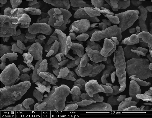
Image (FESEM) of ball milled 2 wt-MWCNT/Cu powder
Microstructure and microhardness
Figure 2 shows the optical micrograph of sintered pure copper and 1 wt-MWCNT reinforced copper nanocomposite. It is evident from the micrographs that the pores existed in as sintered composites. The sintered nanocomposites were subjected to secondary processing such as hot forging to reduce pores and obtain dense compacts. Figure 3 shows that the grains in both hot forged copper and MWCNT/Cu nanocomposite are equiaxed and have fewer pores when compared to that of sintered nanocomposite. Figure 4 depicts the single nanotube in 2 wt-MWCNT/Cu nanocomposite. It is observed that, with the addition of 4 wt-MWCNT content in the copper matrix, clusters of MWCNTs were observed, which are shown in Fig. 5. It can be observed from Fig. 6 that the microhardness of copper matrix was enhanced by the addition of MWCNTs. The microhardness of copper nanocomposites increased with increasing MWCNT content.
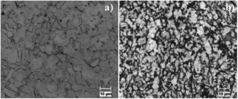
Optical micrographs of a pure copper and b 1 wt-MWCNT/Cu nanocomposite, before hot forging
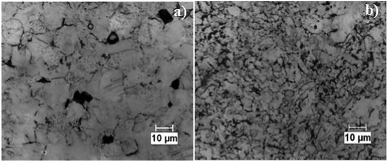
Optical micrographs of a pure copper and b 1 wt-MWCNT/Cu nanocomposite, after hot forging
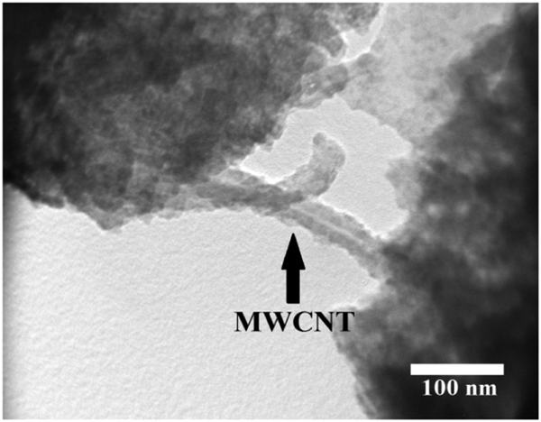
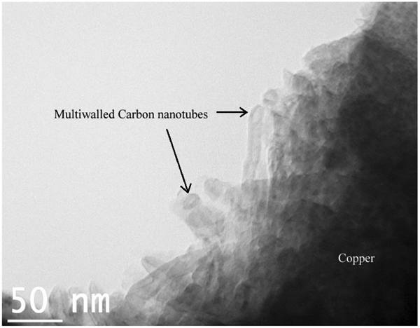
Image (TEM) of 2 wt-MWCNT/Cu nanocomposite
Clusters of MWCNTs in 4 wt-MWCNT/Cu nancomposite
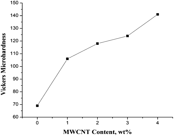
Variation of Vickers microhardness of MWCNT/Cu nancomposites with varying MWCNT contents
Orientation relationship
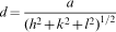
One of the objectives of this study was to study the orientation relationship of MWCNT with respect to copper by ED and stereographic projections. Copper has an fcc structure with a lattice parameter of 3·61 Å and has got a low stacking fault energy of 40 mJ m−2. The thermal expansion coefficient (CTE) mismatch between MWCNT (1×10⁻⁶ K−1) and copper (17×10−6 K−1) is very large. Owing to the large CTE mismatch, prismatic punching of dislocation loops occurs at the MWCNT/Cu interface.17 The unit dislocations a/2 <1 1 1> dissociate into Shockley partials with the Burger's vector as follows18


 ), we obtain R1/R2 = 0·6 and d1/d2 = 0·63. Therefore, the circle of the spots corresponds to (0 0 0 2) and the second one to (
 ) planes. The zone axis or beam direction was calculated to be (
 ).
).
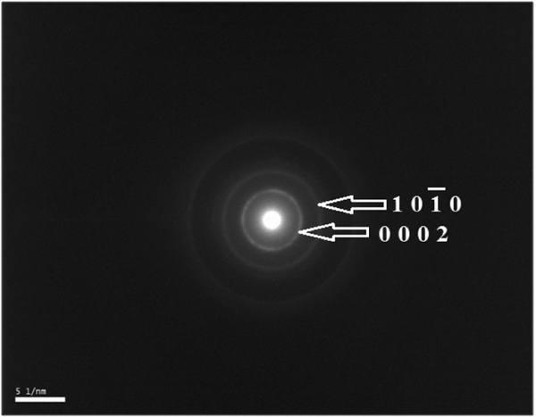
Electron diffraction pattern taken from individual MWCNT
Figure 8a shows the bright field TEM image of 2 wt-MWCNT/Cu nanocomposite. From Fig. 8a, the stacking fault fringes20 depict stacking fault, which binds the two Shockley partials. The stacking fault ribbon gives direct evidence for the CTE mismatch model between MWCNTs and copper. Dynamic recovery has not occurred due to low stacking fault energy of copper during hot forging of the nanocomposite. This is because dislocations cannot climb due to large width of the stacking fault fringe.

Image (TEM) of a dislocations generated at vicinity of MWCNT due to thermal mismatch and b indexed ED form 2 wt-MWCNT/Cu nanocomposites
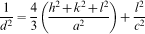
Figure 8b shows the ED pattern from the 2 wt-MWCNT/Cu nanocomposite. The pattern is indexed following the same method as mentioned above. The spots were indexed using the method of radii ratios and plane spacing equation for fcc crystal
 2], which is termed as vector
  . The MWCNT pattern was also indexed, and the first circle corresponds to (0 0 0 2) and the next circle spots to (2 0
  0). The zone axis was [
 4 0]. The tube axis was indexed at 10° from the (1 1 1) spot of FCC copper.
Figure 9 shows the stereographic projection of the nanocomposite pattern,  , i.e. [0
  ] || [
 4 0]. The tube axis is inclined to [1 1 1] pole by 10°, which is indexed as (3 1 1) pole with [0
  1] zone axis, which can be taken as [0
  ]. Therefore, the orientation relationship between MWCNT and copper was [0
  fcc Cu || [
 4 0]MWCNT and the tube axis is parallel to (3 1 1)Cu. However, it is not possible to obtain unique orientation relationship between MWCNT and copper due to the random orientation of MWCNTs in the copper matrix.
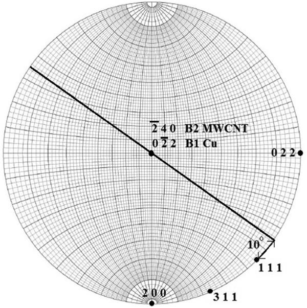
Stereographic projection of 2 wt-MWCNT/Cu nanocomposite pattern
Continuation of the work is needed to find the unique orientation relationship between MWCNTs and copper by subjecting the nanocomposites to unidirectional deformation.
Conclusions
In the present work, MWCNT/Cu nanocomposites were obtained by hot forging process. The microhardness of MWCNT/Cu nanocomposites increased with increasing MWCNT content. The orientation relationship between MWCNT and copper was carried out using ED and stereographic projections. The orientation relationship between MWCNT and copper obtained was [ ]FCC Cu||[
 ]MWCNT with the tube axis parallel to (3 1 1)Cu. It can be concluded that there is no unique orientation relationship between the MWCNT and copper matrix due to the random orientation of MWCNTs.
Footnotes
Acknowledgements
The project was funded by the Institution of Engineers (India), 8 Gokhale Road, Kolkata 700020 under R&D Graint-in-Aid scheme 2011–2012. The authors appreciate the support of Dr. U. Chandrashekar (Gas Turbine Research Establishment, DRDO, Bangalore), Professor D. Jawahar (CEO, PES Group of Institutions), Dr. K. N. B. Murthy (Principal and Director) and Dr. C. S. Ramesh (Mechanical Engineering, PESIT, Bangalore).