
Abstract
The microstructural evolution and structure–property correlation subjected to deep cryotreatment of tool steel were studied. The results show that the retained austenite continues to transform into martensite almost but not complete at low temperature. The topography of retained austenite exhibits as a nanoscale thin film with a thickness range of 20–60 nm between the martensite laths. The changes of internal friction peaks have been explained well by the coupling model, which indicates that deep cryotreatment is not only removing retained austenite but also promoting the interstitial carbon atoms segregated to nearby dislocations under the shrinking strain energy. In addition, more carbides precipitated from the matrix during tempering in cryotreated samples and were verified by analyses of transmission electron microscopy.
Introduction
Cryogenics had its beginning in the mid-19th century when man learned to cool objects to a temperature lower than had ever existed naturally on the surface of the earth. In the 1930s and 1940s, it was shown that this treatment can improve the performance of tool steels. It has been reported that Swiss watchmakers used to store high wear watch parts in Alps snow mountain caves to make frozen condition for stability and wear resistance many years ago. Castings were often left outside in the cold for months or even years to age and stabilise. 1 At present, deep cryotreatment (DCT) is an additive process to conventional heat treatment of tools. In this method, samples usually involved cooling to liquid nitrogen temperature (77 K) and kept at this temperature for a long time and then heated to room temperature (RT). This technique has been proven to be efficient in improving the physical and mechanical properties of the materials such as metals, alloys, plastics and composites. It improves the abrasion, erosion and corrosion resistivity, and durability and stabilises the strength characteristics of various materials. A large number of researches were carried out on cold work tools and high speed steels 2 since they enhance the wear resistance of tools and are good for the dimensional stability. 3 Moreover, the interesting positive effects were noticed on carburised steels, 4 cast irons 5 and stainless steels. 6 From the published works, researchers have proposed three main mechanisms to induce the measured changes in mechanical properties as follows.
Retained austenite elimination
Retained austenite is a softer and unstable phase that is always present after heat treatment in high alloy steels, and it will transform into martensite at low temperature or at the service conditions of tool and die steels. It has claimed that the retained austenite is almost completely eliminated by both shallow and deep cryotreatments. 7 Barron2,8 has attributed the improvement in wear resistance by different cryogenic treatments and the varying response in different materials to the reduction of retained austenite content only after cryogenic treatment. Other researchers9–11 also have suggested that cryogenic treatment carried out after quenching and before tempering almost completely converts the retained austenite in AISI D2 steel to martensite. However, several researchers have reported that tempering stabilises the retained austenite and makes it more difficult to transform.12–14
Fine carbide precipitation
Several researchers2,9,15–17 have pointed out that the improvement of wear resistance after deep cryogenic treatment is considerably higher than that carried out by cold treatment. However, both shallow and deep cryogenic treatments are expected to remove retained austenite almost completely; thus, any difference in their wear resistance must be originating from some other phenomena than the variation in retained austenite content. 7 Collins and Dormer's study 10 is based on the experimental measurement of the population density of fine carbide particles from optical micrographs. Meng et al. 17 have concluded that rather than the removal of retained austenite, improvement in wear resistance by deep cryogenic treatment over cold treatment is due to preferential precipitation of fine η-carbides by deep cryogenic treatment, whereas precipitation of η-carbides occurs only in the early stage of tempering of hardened steel specimens.18–20 Many researchers have not been observed the η-carbides in AISI D2 steel because η-carbide is unstable and hence transforms to more stable carbides like cementite or alloy carbides upon proper tempering treatment.11,18–21 Therefore, it has pointed out that the precipitation of η-carbide is an acceptable explanation for improvement in wear resistance after deep cryogenic treatment. 7
Changes of residual stress
Residual stresses are a result of temperature changes that produce lattice contraction and phase transformation during deep cryogenic treatment. Compressive residual stresses are beneficial in a material for wear and fatigue resistance. 22 The post-tempering DCT has given much beneficial effects on the residual stress state. 23 The transformation of retained austenite to martensite would influence the compressive residual stress, and deep cryogenically treated steel when subjected to tempering has undergone a reduction in compressive residual stress. 24
Moreover, Das et al. 25 found that the improvement of wear resistance due to DCT is much higher when the modes and mechanism of wear between conventionally and cryogenically treated specimens are dissimilar and have dealt with the establishment of relationships between microstructural parameters and properties of AISI D2 steel, subjected to conventional heat treatment and different types of subzero treatments like cold treatment, shallow cryogenic treatment and deep cryogenic treatment. 26 Finite element method simulation and experimental verification of temperature field and phase transformation have recently shown a theoretical guidance to further evaluate the material properties and make the reasonable DCT procedure in deep cryogenic treatment of a tool steel. 27 Akhbarizadeh et al. 28 have investigated the effects of the prior austenite grain size in deep cryogenic treatment on the hardness, structural change and wear resistance of D6 tool steel, showing that smaller austenite grains in the homogenised structures would be the most suitable structures in the deep cryogenic treatment. Oppenkowski et al. 29 have evaluated the factors influencing deep cryogenic treatment that affect the properties of AISI D2 tool steel by Taguchi method. They have concluded that the most significant factors influencing the properties of tool steels are the holding time and the heating rate during deep cryogenic treatment. Amini et al.30,31 have pointed out that there is an optimum holding duration in which the carbides exhibit a maximum percentage and some new nanosized carbides form during the deep cryogenic treatment, increasing the hardness and improving the wear behavior.
Although it has been confirmed that cryogenic processing can improve the service life of tools, the degree of improvement experienced and the underlying mechanism remain ambiguous. The influencing factors involved in DCT are critical enough to account for the significant incongruity in physical properties and microstructural evolution. This paper focuses on the phase transformation at low temperature and physical mechanisms for improving the properties after deep cryogenic treatment, including low temperature martensitic transformation and carbon atoms diffusion, the stability of retained austenite, the effects of carbide precipitation kinetics, and the correlation between properties and microstructure.
Experimental
Material and treatments
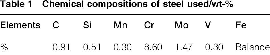
The material used to prepare samples in this study was a newly developed cold work tool steel (designed by Wu in Shanghai University, China) rod, which was fabricated by vacuum induction melting and electroslag remelting and then forged to a diameter of 180 mm. The chemical compositions are listed in Table 1.
Chemical compositions of steel used/wt-
The samples prepared for internal friction experiments were cut into beam shapes with 55 mm in length, 10 mm in width and 1 mm in thickness. All the samples were austenised at 1313 K for 10 min in a protected atmosphere and then hardened into oil. The deep cryogenic treatment of the samples was done by uniform cooling into liquid nitrogen and soaking for 40 h. In addition, the quenched samples and the DCT treated samples were tempered at 483, 693 and 793 K for 2 h.
Experimental methods
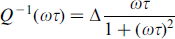
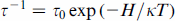
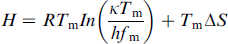
The temperature dependence of internal friction (TDIF) was measured in a torsion pendulum (simultaneous measurement equipment for elastic modulus and internal friction, EG-series, Nihon Techno Plus Co. Ltd) by free decay method with high vacuum in the temperature range from RT to 773 K at resonance frequencies (shear modulus in relative units). The internal friction spectra have been involved into broaden Debye peaks and a background. Internal friction (Q− 1) was measured from the free decay of the oscillations, in case of a relaxation effect with a single relaxation time described by the Debye equation according to
32
:

The microstructures of the samples were characterised by using optical microscopy (OM) (Nikon LV150), scanning electron microscopy (SEM) (JEM-6700F) and transmission electron microscopy (TEM) on a JEOL 2010F TEM operated at a voltage of 200 kV. For OM observations, the samples were mechanically polished using diamond paste and then etched at RT in an alcohol solution containing 4 vol.- nitric acid. TEM foils were cut at different subsurface layers, mechanically thinned to 30 μm thick by grinding and finally electropolished from the untreated side of the samples after the removal of surface layers of different thicknesses. The electropolishing was carried out at 253 K with an electrolyte of 5 vol.- perchloric acid and 95 vol.- alcohol.
The phase constitution of the samples at RT was identified by X-ray diffraction (XRD) analysis using a Rigaku D/max 2400 X-ray diffractometer with Cu Kα (λ = 1.5418 × 10− 10 m) radiation and vanadium filters in a step size of 0.02°. The peaks correspond to the retained austenite, martensite and carbides in the XRD patterns. The volume fraction of retained austenite was estimated in accordance to ASTM standard E975-00 standard, 50 considering the diffraction crystal plane (200), (220), (311) of retained austenite and (200), (211), (220) of martensite. Thermal expansion analyses of the samples (Φ4 × 10 mm) were conducted on a Baehr-thermo DIL 805A/D dilatometer to study martensitic transformation. The dilatometric specimen was first heated up to 1313 K at a heating rate of 30 K s− 1 in vacuum, held for 300 s and subsequently cooled with a cooling rate of 30 K s− 1. In order to obtain the martensitic finish temperature (Mf), a flow of liquid nitrogen is taken as a cooling medium when the temperature of the specimen is < 373 K. Moreover, four-probe impedance test was adopted as the electrical part in the electrical resistivity experiments. The samples were also measured in order to describe the physical mechanism effects of deep cryogenic treatment. Specimens of 2 mm × 3 mm × 60 mm were prepared from the tempered samples. The specimens were mechanically polished, and then the electrical resistivity was measured at an elevated temperature from RT using a Digital Source Meter (Keithley, model 2400) and a Nanovolt Meter (Keithley, model 2182) according to ASTM fig76-86. For all hardness measurement, Rockwell hardness tester HR150A was used. Unnotched sheets (10 mm × 10 mm × 55 mm in size) were prepared for impact toughness test, and the impact toughness was the average of five samples.
Results and discussion
Dilatometry
Figure 1 shows the change in the length of the sample cooled from 1313 K down to 173 K. According to the dilatometric curve obtained from dilatometric test, the austenitic transformation started at 1120 K and finished at ∼1175 K. The transformation of martensite started at 498 K and finished at ∼193 K.
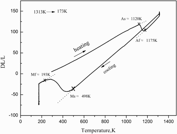
Dilatometry of tested steel during cooling from 1313 to 173 K with cooling rate of 30 K min− 1 and under flow of liquid nitrogen below 373 K, Ms ≈ 498 K, Mf ≈ 193 K
Electrical resistivity
The electrical resistivity of a conducting solid can be experimentally determined without much difficulty, and for many years, it has been used as a research tool to investigate various microstructural and physical phenomena.
39
The electrical resistivity is related to the defects in materials, and it is proportional to the defects. It is one of the characteristic physical properties of materials and is dependent on temperature and on crystal defects, such as solute atoms, dislocations and impurities. The temperature dependent electrical resistivity of the quenched and DCT treated samples after tempering at 483 K for 2 h is presented in Fig. 2. It shows the evolution of the relative electrical resistivity as a function of temperature of the quenched and DCT treated samples. From the comparison of temperature dependent electrical resistivity after the same conditional tempering of quenched and DCT treated samples, it is clear that the temperature dependent electrical resistivity of the DCT treated sample is lower than that of the quenched sample. Researchers40–42 have pointed out that the resistivity signal is due to a complex interaction of various scattering centres including vacancies, grain boundaries, dislocations, clusters and precipitates. The electrical resistivity rises with the increase of the solubility of carbon atoms in solid solution according to the Matthiessen rule:
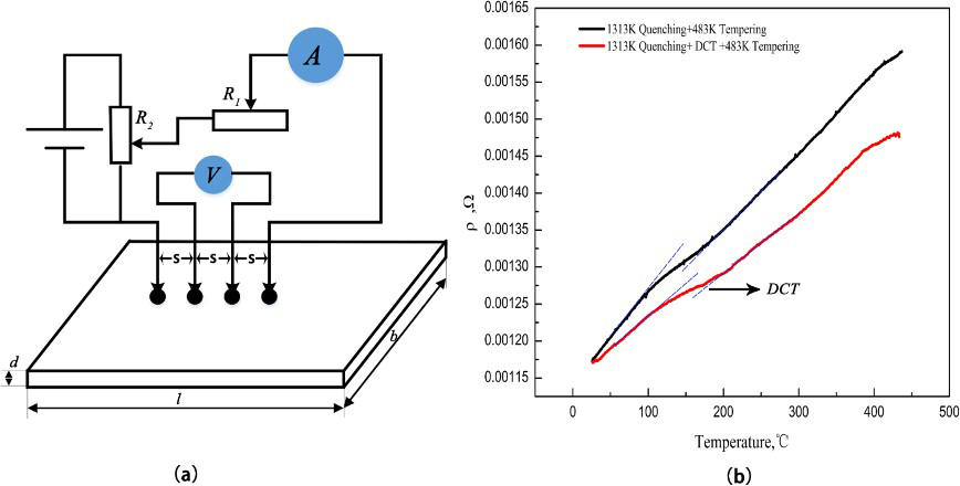
a schematic diagram of four-point probe method for electrical resistivity test; b temperature dependent electrical resistivity
Internal friction
Internal friction of tempering after quenching
Figure 3 illustrates the TDIF of the samples quenched at 1313 K and DCT treated in liquid nitrogen soaking for 40 h. The internal friction has been involved into broader than Debye peaks after subtracting background. By comparing the internal friction spectra results of the quenched and DCT treated samples, it can clearly be shown that the height of Snoek peak is decreased after deep cryogenic treatment. Moreover, the Snoek–Kê–Köster (SKK) peak is broader than a single Debye peak in a single relaxation time with an activation energy between 1.40 and 1.50 eV. By comparing the height of SKK peak of the quenched and DCT treated samples, it is clearly noted that the height of SKK peak is increased after DCT.
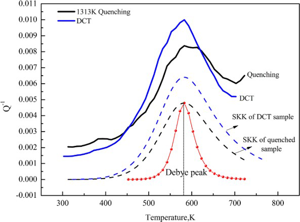
TDIF spectra of quenched and DCT treated sample
Tempering of martensitic steels involves the segregation of carbon, the precipitation of carbides, the decomposition of retained austenite, and the recovery and recrystallisation of the martensitic structure. 43 Tempering of iron–carbon martensite is accompanied by a redistribution of carbon atoms in a solid solution with the resulting precipitation of carbide. Samples were tempered in successive steps in order to vary the concentration of carbon in solid solution in the martensite. Internal friction measurements have been carried out immediately after tempering at different temperatures at 453, 693, 793 and 873 K to study the tempering timely phenomenon. The TDIF of the quenched sample and tempered at different temperatures for 2 h is shown in Fig. 4. It is clear that the internal friction peaks are decreased, while the tempering temperature is raised (see Fig. 4a). With rising tempering temperature, the peak temperature Tm increased and the internal friction peak disappeared after tempering at 873 K for 2 h. The tempering proceeds by a sequence of structural changes, including recovery of the dislocation structure and precipitation of carbides. 44 The interaction between dislocations and point defects is one of the main sources of Snoek–Köster (SKK) relaxation in materials according to internal friction theory.32,33 The dislocation structure almost recovered when tempered at 873 K for 2 h, resulting in disappearance of Snoek–Köster (SKK) relaxation.
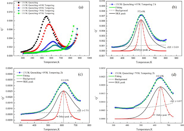
TDIF of quenched sample and tempered at different temperatures for 2 h: a internal friction spectra of different treatments; b–d internal friction spectra of quenched samples were involved into somewhat broader than standard Debye peak and exponential background according to equations (3) and (5) after tempering at 453, 693 and 793 K respectively
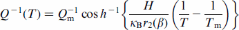
In Fig. 4b–d, the internal friction spectra of quenched samples were involved into somewhat broader than a standard Debye peak and an exponential background according to equations (3) and (5) after tempering at 453, 693 and 793 K. The corresponding relative peak width r2 (β) is 2.642, 2.751 and 3.057 after tempering at 453, 693 and 793 K respectively and being subtracted from the background according to equation (5). Wang et al. 45 have proposed that the cooperative nature of the motions of the interstitial solute atoms when dragged by the dislocations is the primary cause of the S–K peak broadening according to coupling model for the description of relaxations in complex correlated systems.46,47 The coupling model is based on the consideration of the cooperative migration of the foreign interstitial atoms (FIAs), which is caused by two kinds of interactions, including the FIAs themselves and between the FIAs with time dependent strain field of dislocations. 48 Therefore, the reason for the decrease of internal friction spectra height is attributed to the dislocation structure almost recovering and the carbide formation of interstitial carbon atoms in martensitic matrix during tempering. In addition, the peak temperature moves towards higher after tempering at higher tempering temperature from Fig. 4a. This may be due to the frequency changes of the material caused by internal state that was changed after different treatment, such as the carbide precipitation.
Internal friction of tempering after DCT
The TDIF of DCT treated sample and then tempered at different temperatures for 2 h is presented in Fig. 5. The TDIF of DCT treated and non-DCT treated samples after tempering for 2 h at 453 and 693 K respectively is shown in Fig. 5a. It is clear that the SKK peak height of the DCT treated samples is lower than that of the non-DCT treated samples at the same tempering temperature for 2 h. Published works9–11 have pointed out that the retained austenite is eliminated almost after deep cryogenic treatment. Thus, the phase transformation of the DCT treated sample is mainly the decomposition of martensite during the tempering process. As is known, the decomposition of martensite involves the segregation of carbon at dislocations and the precipitation of carbides in the tempering. That is, the interstitial carbon atoms in martensite matrix were decreased after tempering because of the carbide precipitation during the process of tempering. Thus, we can regard as there are less interstitial carbon atoms in the DCT treated samples than quenched samples after tempering according to the mechanism of the SKK peak production under the oscillation stress. In Fig. 5b–d, the internal friction spectra of DCT treated samples were involved into somewhat broader than a standard Debye peak and an exponential background according to equations (3) and (5) after tempering at 453, 693 and 793 K respectively. The corresponding relative peak width r2 (β) also increases after tempering at 453, 693 and 793 K and being subtracted from the background according to equation (5). It is similar to the quenched samples after tempering at the same temperature, and this has been successfully explained by Wang et al., 45 as shown in Fig. 4.
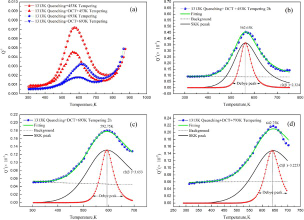
TDIF of DCT treated sample and tempered at different temperatures for 2 h: a internal friction spectra of different treatments; b–d internal friction spectra of DCT treated samples were involved into somewhat broader than standard Debye peak and exponential background according to equations (3) and (5) after tempering at 453, 693 and 793 K respectively
The coupling model has considered the interactions between the FIAs themselves, which was neglected by Schoeck. The interactions between the FIAs in the Cottrell atmosphere are stronger than the long range interactions between FIAs in the perfect body centred cubic lattice. 49 This result also indicates that the interstitial carbon atoms segregate to nearby dislocations in the process of deep cryogenic treatment, and then these segregated carbon atoms nearby dislocations act as growing into nuclei for carbide during tempering.
XRD analysis of phase change before and after DCT
The XRD technique is used to determine the phase transformation before and after deep cryogenic treatment, as labeled in Fig. 6. It is clear from the figure that the peaks of the retained austenite exhibit a low intensity value after DCT, which indicates that the retained austenite transforms into martensite during the DCT process, as plotted in Fig. 6a. However, the retained austenite cannot transform into martensite completely even when keeping the sample in liquid nitrogen for 24 h, as shown in Fig. 6b. The authors have pointed out that the volume fraction of retained austenite in sample is ∼2.79 after soaking for 24 h in liquid nitrogen, 51 while it is 23.25 in quenched sample before DCT. In addition, Li et al. 52 have predicted the retained austenite evolution in the same steel during deep cryogenic treatment by means of finite element simulation based on a multiphysical field coupling numerical model. The retained austenite contained in quenched specimen will continue to convert to martensite during deep cryogenic treatment. The amount of retained austenite can be significantly decreased, and finally, its volume fraction is ∼2.36 after DCT. The computational simulation results are coincident with the experimental data obtained from the XRD of Li et al. 51
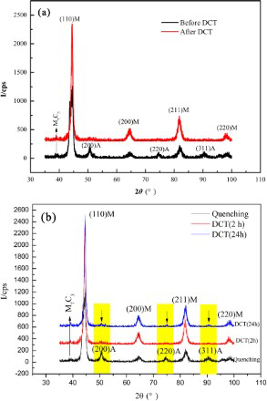
XRD pattern and calibration of specimen before and after DCT
Morphologies of retained austenite and stabilisation
As mentioned in the above, a large amount of austenite (23.25) was retained after quenching and the retained austenite cannot transform into martensite completely even when keeping the sample in liquid nitrogen for a long time by means of XRD. The morphological variation of retained austenite before and after DCT has been evaluated by the TEM, as presented in Fig. 7. The microstructure of the quenched sample is composed of the lath and plate martensite and thin film retained austenite with a thickness of >100 nm (see Fig. 7a). However, the retained austenite will be remarkably reduced after the specimen was subjected to liquid nitrogen, as discussed by XRD. The topography of retained austenite exhibits as a nanoscale thin film with a thickness range of 20–60 nm between the martensite laths and stably exists even after prolonged soaking time in liquid nitrogen, as illustrated in Fig. 7b.
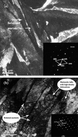
Morphologies of retained austenite: a conventional treatment (1313 K quenched+483 K tempered for 2 h); b DCT treated sample after tempering [1313 K quenched+DCT (77 K for 40 h)+483 K tempered for 2 h]
As is well known, aging or tempering of as hardened steel can make the retained austenite stabilised.53–55 During aging or tempering of as hardened steel samples, the carbon atoms initially diffuse primarily from martensite to the martensite/austenite interfaces and segregate there; thus, the normally mobile dislocations are anchored by the segregated carbon atoms, while at later stages the diffusion of carbon atoms into austenite takes place, resulting in enrichment of carbon in austenite. 56 This phenomenon is generally called as thermal stabilisation of austenite, which is well known to hinder the transformation of retained austenite to martensite.56,57 The thermal stabilisation of austenite occurs because of the pinning of martensite nucleus/austenite matrix interfaces by segregated carbon 58 and the carbon partitions from the supersaturated martensite phase to the untransformed austenite phase, thereby increasing the stability of the residual austenite upon subsequent cooling to RT.59,60 In addition, the stability of austenite as the result of thermal stabilisation depends not only on its susceptibility to transform during deep quenching but also on the martensitic transformation under the mechanical loads. 61 The microresidual stresses are generated during diffusionless martensitic transformation by dislocations and by solute carbon atoms remaining in their octahedral sites without diffusion.62,63 However, the interstitial carbon atoms also can migrate to the defects such as dislocations or martensite/austenite interfaces due to the lattice shrinking strain energy at cryogenic temperature. On subsequent tempering, these interstitial carbon atoms act as nuclei for the formation of fine carbide particles nearby dislocations, and the carbon atoms near martensite/austenite interfaces may diffuse into retained austenite, resulting in enrichment of carbon in retained austenite and making the retained austenite stabilised.
Precipitation kinetics evaluated by internal friction
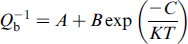
The diffusion of carbon in iron can affect mechanical properties by three mechanisms. These are the stress induced ordering of carbon atoms among the possible sets of interstitial sites, 64 the segregation of carbon to dislocations to form Cottrell atmosphere 65 and the precipitation of carbides. Internal friction tests were performed to examine the kinetics of the interstitial carbon atom segregation and carbide precipitation during tempering at 453, 693 and 793 K. Figure 8 shows the TDIF spectra after quenching and DCT treating (Fig. 8a) and then tempering at different temperatures for 2 h (Fig. 8b–d). It is clearly noted that the height of SKK peak is increased after deep cryogenic treatment. This phenomenon indicates that the carbon atoms segregate to nearby dislocations and produced strong interactions, including the FIAs themselves and between the FIAs with time dependent strain field of dislocations by the coupling model.66–68 However, from Fig. 8b–d, it is clear that the height of SKK peak of DCT treated sample is lower than that of the non-DCT treated sample after tempering at the same conditions. The relaxation strength of the quenched sample is higher than that of the DCT treated sample after tempering at the same conditions. This indicates that the interstitial carbon atoms nearby dislocations in DCT treated samples are less than the non-DCT treated samples after tempering at the same conditions according to the coupling model of SKK relaxation.45,67
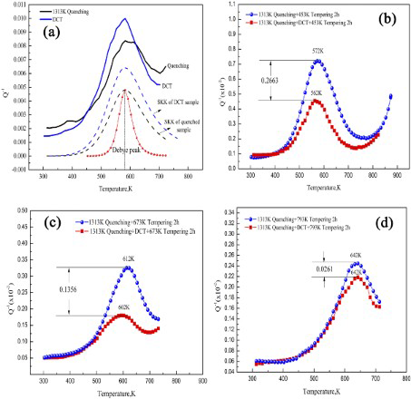
TDIF spectra: a spectra of quenched and DCT treated samples; b–d spectra of quenched and DCT treated samples after tempering at 453, 673 and 793 K for 2 h respectively
Very little information is available on the internal friction effects, which are sometimes associated with precipitation from supersaturated solid solutions.69,70 Actually, much more effort has been made to study the influence of solute atoms on internal friction.64,71 The influence of precipitation on internal friction is very complex as can be seen from aluminum alloys, which have obtained relatively much attention. 69 Yening et al. 70 have pointed out that during precipitation, the internal friction peak height decreases with increasing measurement frequency f and decreases with decreasing cooling (or heating) rate. As shown in Fig. 8b–d, the peak height of quenched sample is lower than that of the DCT treated sample after tempering at 453, 693 and 793 K. In addition, the height difference value is 0.2663, 0.1356 and 0.0261 respectively after tempering at 453, 693 and 793 K for 2 h. The variation of peak height is attributed to the change of relaxation strength caused by the interaction of interstitial carbon atoms and dislocations according to the coupling model due to the same quenching temperature and tempering conditions. This indicates that the interaction between interstitial carbon atoms and dislocations decreased with the increase of tempering temperature. In other words, the interstitial carbon atoms that are situated nearby dislocations decreased in the DCT treated samples after tempering. The martensite becomes more supersaturated with decreasing temperature and increases its lattice distortion and thermodynamic instability. 7 That is, there are more carbides that precipitated from the matrix after DCT treated samples during tempering. Moreover, a large amount of carbides precipitated at low temperature according to the peak height difference value. It is clear that the interstitial carbon atoms migrated and segregated nearby dislocations because of shrinking strain energy during deep cryogenic treatment.
Characterisations of carbide precipitation after tempering
The microstructure of the samples before and after DCT and the diffraction of precipitation in tempered martensite illustrated by TEM are illustrated in Fig. 9. The typical martensitic structure of tempered samples before DCT consists of a matrix, which is made of plate and lath martensite as well as a substantial fraction of retained austenite between the plates of martensite, as demonstrated in Fig. 9a and b. The analysis of electron diffraction has disclosed a number of ε-carbide particles in the martensite obtained in the non-DCT treated samples. However, a dramatic change in the morphology of the microstructure in DCT treated sample is observed after tempering. The DCT treated and then tempered martensite demonstrates a twined microstructure, and there are a large number of carbides that precipitated between the twinned martensite in the process of tempering, as shown in Fig. 9c–f. In this case, the martensitic matrix is heavily decorated by a large number of fine particles as compared with the non-DCT treated samples.
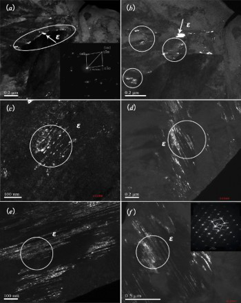
TEM images showing a, b precipitates of ε-carbide and diffraction pattern after tempering at 453 K for 2 h of steel quenched at RT and c–f characteristics of ε-carbide in liquid nitrogen for 40 h treated sample and diffraction pattern after tempering at 453 K for 2 h of steel quenched at RT
The authors have pointed out that the deep cryogenic treatment refines the secondary carbides, increases their amount and population density, and leads to more uniform distribution by categorisation of the secondary carbides.72–74 TEM studies of the simple after low temperature tempering were undertaken to clarify this topic in this paper. Tempering at 473 K after quenching of steel at RT is accompanied by the precipitation of the ε-carbide. This is also suggested by Gavriljuk et al., 75 and it does not lead to the precipitation of ε-carbides while the sample was tempered at 373 K after holding at − 123 K. The TEM micrograph shows that along with the formation of microsized carbides, some new nanosized carbide is also formed in the matrix after deep cryogenic treatment during tempering. These newly formed carbides increase the carbide content and make a more homogenised carbide distribution after deep cryogenic treatment. According to Das et al.,9,76 the martensite becomes more supersaturated with decreasing temperature and increased the thermodynamic instability, resulting in the segregation of carbon atoms to nearby defect forming clusters. The interstitial carbon atoms segregate to nearby dislocations and produced strong interactions with time dependent strain field of dislocations according to the coupling model.48,67,77 Therefore, along with the results for SKK relaxation (see Fig. 8), the TEM studies provide a direct evidence of more carbides precipitating from the matrix after the DCT treated samples during tempering.
Correlation between properties and microstructure
Figure 10 gives the hardness variation of the tempered samples (before and after DCT) at different tempering temperatures. It is shown that the hardness of DCT treated samples is higher than that of the quenched samples below 693 K. This can be attributed to the transformation of retained austenite to martensite during DCT.51,78 As presented in Fig. 6 of XRD results, the peaks of retained austenite exhibit a low intensity value after DCT, which validates that the retained austenite transformed into martensite during DCT. Moreover, the secondary hardening effect was produced in both quenched and DCT treated sample. The microstructure in affine dispersion consists of the so called secondary hardening nanoscale secondary carbides, principally vanadium, molybdenum and chromium carbides. 79 The secondary hardening depends on alloy composition and heat treatment history, and the secondary carbides are usually MC and/or M2C in previous studies.80,81 As plotted in Fig. 10, the secondary hardening effect of quenched sample is higher than that of the DCT treated sample. On the one hand, the retained austenite of quenched sample transformed into martensite during cooling after tempering. As mentioned in Fig. 8, a large number of carbides precipitated from the matrix after DCT at lower temperature than non-DCT treated samples in the decomposition of martensite in high alloying steels. Thus, the secondary hardening is mainly related to transformation of retained austenite during the cooling after tempering and the precipitation of carbides like M23C6, MC and M2C in the decomposition of martensite in high alloying steels.
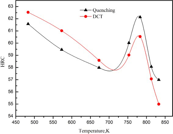
Hardness variation with tempering temperature of quenched and DCT
Figure 11 illustrates the hardness and toughness of quenched and DCT treated samples after tempering at 726 K for 4 h. It shows that the hardness is increased but the toughness is decreased after DCT. As shown in Fig. 6, a large amount of austenite (23.25) was retained after quenching. However, Das et al. 7 have reported that both shallow and deep cryogenic treatments are expected to remove retained austenite almost completely. This indicated that the hardness increase after deep cryogenic treatment is mainly caused by the transformation of retained austenite into martensite.51,82 The retained austenite film is a soft phase in steel, which is beneficial to fracture toughness. 83 The retained fraction of ductile austenite can act as a crack arrestor in the propagation phase and alleviate the stress concentration of the crack tip.82,84,85 As discussed above, the retained austenite was almost removed completely after DCT, and it is inevitable that the toughness decreased after DCT.
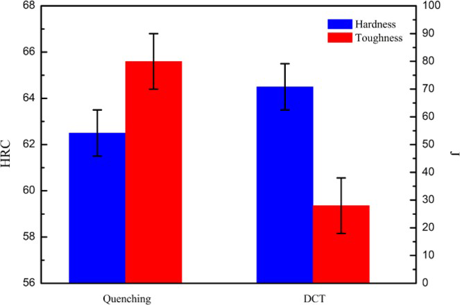
Comparison of mechanical properties of quenched and DCT treated samples after tempering at 483 K for 4 h
Conclusions
The mechanical properties of the tool steel show an increase of hardness and decrease of toughness after deep cryogenic treatment. Moreover, the secondary hardening effect of quenched sample is higher than the deep cryotreated sample. This indicates that the secondary hardening is mainly related to transformation of retained austenite during the cooling after tempering and the precipitation of carbides like M23C6, MC and M2C in the decomposition of martensite in high alloying steels.
The retained austenite continues to transform into martensite at low temperature. The topography of retained austenite exhibits as a nanoscale thin film with a thickness range of 20–60 nm between the martensite laths and stably exists even after prolonged soaking time in liquid nitrogen while the thickness is >100 nm before DCT.
The changes of internal friction peak height and width have been explained well by the coupling model, which is based on the consideration of the cooperative migration of the FIAs C, N and O caused by two kinds of interactions, including the FIAs themselves and between the FIAs with time dependent strain field of dislocations. This indicates that deep cryogenic treatment is not only removing retained austenite almost but also promoting the interstitial carbon atoms segregated to nearby dislocations under the shrinking strain energy.
More carbides precipitated from matrix after deep cryotreatment during tempering. The precipitation kinetics was evaluated by internal friction, and characterisations of carbides after tempering was verified by analyses of TEM.