
Abstract
Additive manufacturing is increasingly considered for production of high quality, metallic, aerospace parts. Despite the high potential of this manufacturing process to reduce weight and lead time, the fundamental understanding of additive manufactured Ti–6Al–4V material is still at an early stage, especially in the area of fatigue and damage tolerance. This paper covers the effects of inherent surface roughness on the fatigue life. In the as built condition, metallic parts have a poor surface texture, which is generally removed in fatigue critical areas. It is shown that the fatigue properties of Ti–6Al–4V samples, produced by direct metal laser sintering and electron beam melting, are dominated by surface roughness effects. A simple model based on an equivalent initial flaw size is formulated.
Introduction
Additive manufacturing (AM) can produce complex shaped metallic parts without the need for dies, form tools or moulds. The parts are effectively grown rather than machined from a larger block. A three-dimensional model is virtually sliced into thin layers and send to a manufacturing unit, in which an energy source directly builds the part by joining material layer by layer.1,2 Lead time reduction and design freedom are some of the main drivers for AM within the aerospace industry.2,3 Compared to metallic forged or cast components, better material utilisation and the avoidance of tooling lead to potentially lower costs, whereas the design freedom is an enabler for weight savings through topology optimisation.
It is known that the AM process produces new material challenges with associated features like defects or inherent surface roughness, which can lower the fatigue performance.4–6 However, it is shown for additive manufactured Ti–6Al–4V using wire that in the absence of these features, the mechanical properties can be compared to wrought material. 7 The same trend can be seen for powder bed processes, if a post-processing, like hot isostatic pressing (HIP), is applied to reduce internal defects of milled specimens. In the absence of defects, the fatigue performance is increased and scatter is reduced. 5
Aside from the effect of defects, recent studies have investigated the influence of surface roughness on the fatigue performance.6,8–10 Wycisk et al. 8 reported a significant lower endurance limit of ∼210 MPa (R = 0.1, Kt = 1) for specimens with inherent surface roughness compared to polished one (500 MPa).
Mastering the influence of inherent surface roughness from a damage tolerance assessment point of view could be key to assure the reliability of future structural applications.
In the framework of a larger effort undertaken in Airbus Group, this work will describe the fatigue performance of Ti–6Al–4V samples, produced by direct metal laser sintering (DMLS) and electron beam melting (EBM) with rough surfaces (as built). The aim is to offer a better experimental documentation, as well as to elaborate a practical engineering approach, to estimate the fatigue performance of as built specimens based on linear elastic fracture mechanics.
Experimental
Manufacturing process and heat treatment
Two different manufacturing processes are investigated; in the first, samples are produced by DMLS using an EOSINT M 280 (EOS) platform, with the standard parameter from EOS, shown in Table 1. The builds take place under protective argon atmosphere, with a process chamber temperature of ∼35°C. The scan strategy is based on a shell and core concept, rotating each layer with an angle of 30°. The second method ultilises EBM performed using an ARCAM A2 (ARCAM AB) platform to manufacture identical samples for a direct comparison between the techniques. Unlike DMLS, the EBM process is performed under vacuum (∼5x10³ mbar, with a process chamber temperature of ∼620°C. The utilised shell core scan strategy alternates each layer between 0 and 90° (Table 1).
Used parameters for DMLS and EBM Ti–6Al–4V
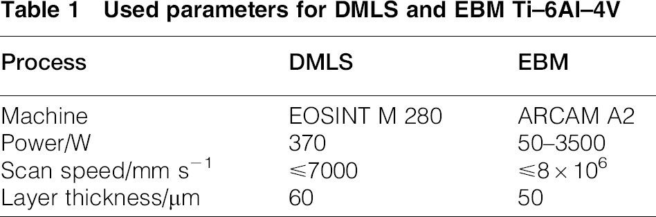
All parts are heat treated at 710°C for 2 h under vacuum, followed by furnace cooling under argon atmosphere, to reduce residual stresses. 11 Especially for DMLS parts, high cooling rates and steep temperature gradients can tend toward the formation of residual stresses. 12 Leuders et al. 13 investigated residual stress for DMLS parts before and after a heat treatment at 800°C for 2 h. Nearly no residual stress remained in the material.
Mechanical characterisation
Static tensile, axial fatigue and fatigue crack growth tests are performed at ambient condition. The load is applied perpendicular to the layer deposition direction.
Static tensile tests are performed on a servo hydraulic test machine Z 250 (Zwick), in accordance to EN 2002,
14
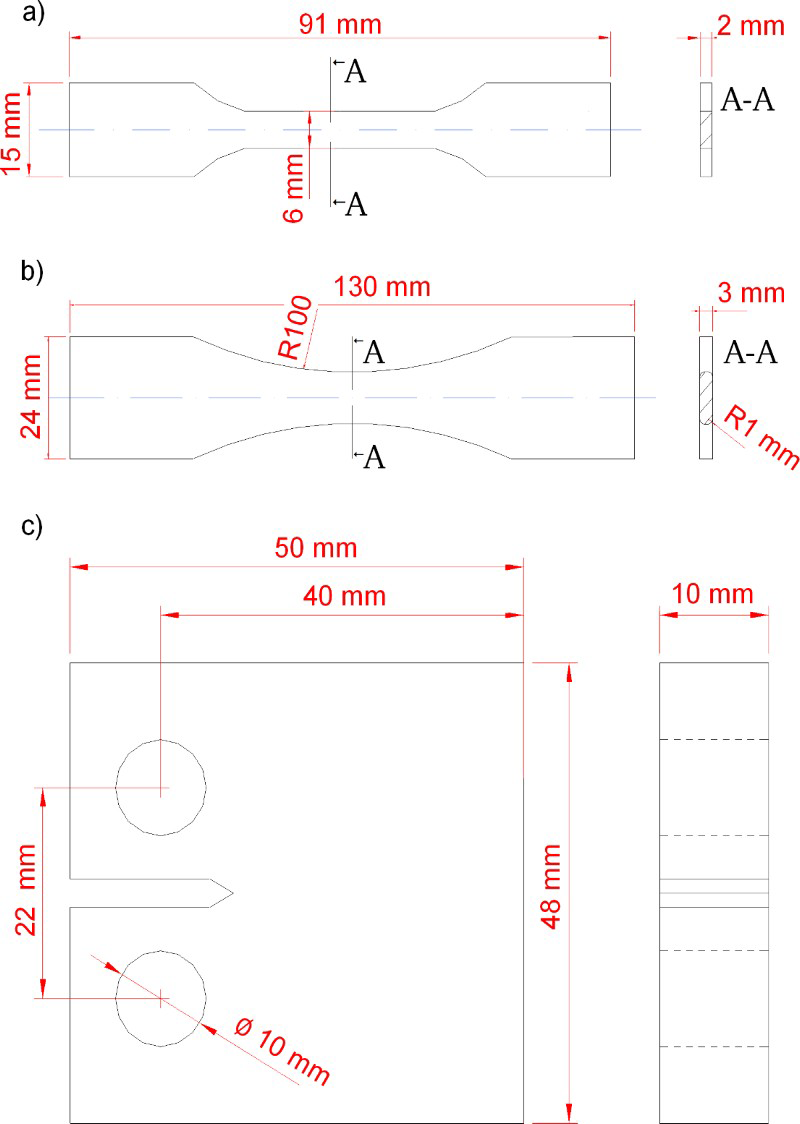
on flat specimens (Fig. 1a). A strain rate of 0.5 min− 1 is applied for yield strength at 0.2 (Rp0.2) and 2 min− 1 for tensile strength (Rm). Elongation (A) is calculated based on an extensometer gauge length of 20 mm. Three to four test samples are used to calculate an average value. Axial fatigue tests are performed on a resonant testing machine, Microtron (Rumul), in accordance to EN 6072.
15
Flat specimens (Kt = 1; Fig. 1b) are tested under a constant load, with a load ratio of R = 0.1 at 150 Hz. It has to be noted that the reported fatigue limit is statistically not proven due to the amount of 10–11 specimens for each SN curve. Fatigue crack growth tests are performed using a servo hydraulic test device, PC 160N (Schenck), in accordance to ASTM E 647.
16
A compact tension specimen [C (T) 40, Fig. 1c] is used under constant load (R = 0.1). The crack size is measured by the electrical potential drop method. Specimen geometries: a static tensile test specimen, b axial fatigue test specimen and c fatigue crack growth test specimen
Roughness measurements
Roughness measurements are performed using contact profilometry with a DektakXT (Bruker) in accordance to DIN EN ISO 4288:1998. 17 The average value of three measuring sections in the build direction describes the arithmetic average height (Ra) and the maximum height (Rt) of the profile. All measurements are based on the used axial fatigue specimens.
Estimation model
A simple estimation model is proposed based on an equivalent initial flaw size (EIFS) approach to total life estimation. In short, this is a method where cracks are analytically grown backwards to a time equal to zero (time or cycles) to determine an initial flaw, referred to as an EIFS. By growing a number of cracks back to a time equal to zero, a distribution of EIFS can therefore be established; the method is widely used within commercial aerospace manufacturing.18–20 Here, a deterministic approach is utilised for simplicity.
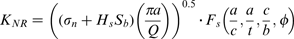
Takahashi and Murakami 21 have shown that it is possible to relate characteristic surface roughness values to an EIFS. On the basis of these findings, an EIFS is back extrapolated from SN data and linked to the experimentally determined surface roughness value (Rt). The flaw geometry is described by a semielliptical surface crack.
The calculation of the stress intensity factor (SIF) is taken to be
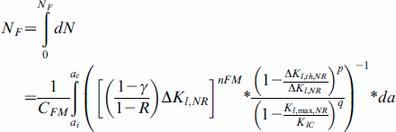
The experimentally determined crack growth curves are described by the Forman/Mettu equation (NASGRO crack growth equation):
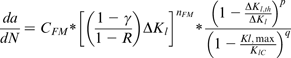
Detailed descriptions including all parameters can be found in the work of Forman and Mettu. 23
By combining both equations, the initial crack length (ai) can be calculated based on the cycles to failure (NF) for each experimental value as follows:
SN curves are estimated for different surface roughness by the assumption of a linear relationship between surface roughness and EIFS.
In order to keep the model as simple as possible, the following assumptions are made:
Fatigue life estimations are based on linear elastic fracture mechanics. Fatigue crack initiation is neglected. Fatigue crack propagation of short cracks is neglected.
Results
Roughness characterisation
The surface roughness can influence the fatigue performance due to multiple stress concentrations. Figure 2 therefore shows a typical DMLS (Fig. 2a) and EBM (Fig. 2b) surface.
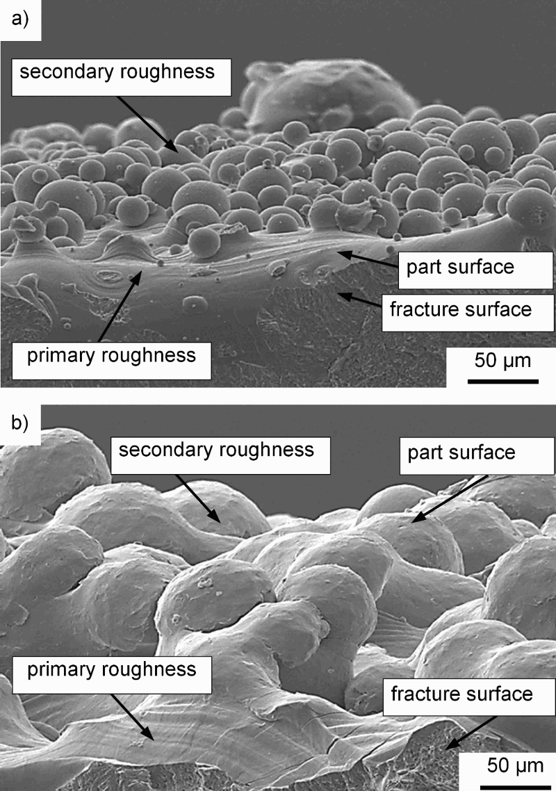
Surface roughness of Ti–6Al–4V: a DMLS (side view), b EBM (side view)
It is notable that both processes show two types of roughness:
Roughness induced due to solidification of the melt pool (primary roughness). Roughness induced by partly melted powder particles (secondary roughness).
The results from the sieve analysis, in accordance to ASTM B214, indicate a maximum particle size for EBM powder more than twice as high as for DMLS, which results in a higher surface roughness of the EBM material.
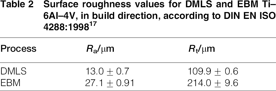
As a consequence, the roughness values for the EBM specimens are higher (Ra: 27 μm, Rt: 214 μm) compared to the DMLS specimens (Ra: 13 μm, Rt: 110 μm), shown in Table 2.
Surface roughness values for DMLS and EBM Ti–6Al–4V, in build direction, according to DIN EN ISO 4288:199817
Mechanical characterisation
Tensile properties
The tensile properties are summarised in Table 3. Each test series consists of three to four specimens. The DMLS tensile specimens show high ultimate tensile strength (UTS) of 1096 MPa, with elongation of 12. The average UTS of the EBM specimens is slightly lower at 965 MPa, while elongation is reduced to 6.
Average tensile tension properties including standard deviation for DMLS and EBM Ti–6Al–4V, build direction: ZX, heat treatment: 710°C/2 h, surface: as built
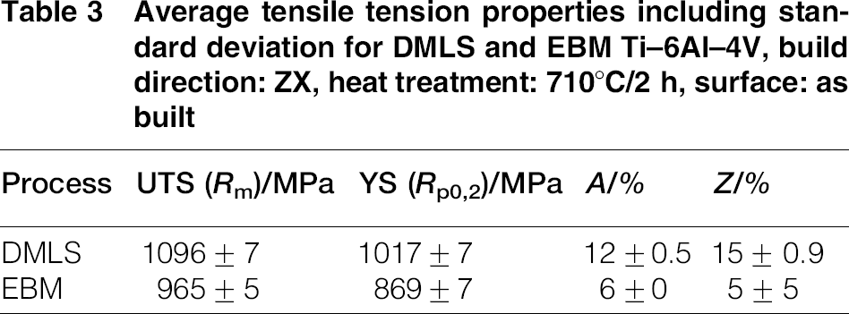
It has to be noted that defects can be detected on the fracture surface of the EBM specimens. Furthermore, first chemical analysis of the specimens reveals a notably lower aluminium content (DMLS: 6.5 wt.-, EBM 5.9 wt.-) and lower oxygen content (DMLS: 0.17 wt.-, EBM 0.13 wt.-) for the EBM specimens.
Fatigue crack growth properties
To estimate the fatigue properties, the crack growth was measured and plotted logarithmically as a function of the stress intensity range (Fig. 3).
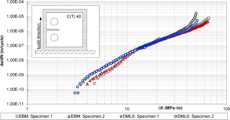
Fatigue crack growth properties of DMLS and EBM Ti–6Al–4V, C (T) 40, R = 0.1, build direction: XZ, heat treatment: 710°C/2 h, surface: milled
The processes differ mainly in the threshold regime, where the crack growth is reduced for the EBM specimens.
Experimental and estimated high cycle fatigue properties
The high cycle fatigue behaviours of DMLS and EBM Ti–6Al–4V are plotted in Figs. 4 and 5. Fractographic analysis reveals multiple cracks initiating at the surface. Standard deviations of 19.6 MPa for DMLS and 6.5 MPa for EBM were calculated based on a SN curve with 50 probability of failure. The fatigue limit (1 × 10⁷) is slightly higher for the DMLS specimens when compared directly to the EBM specimens (DMLS: Smax = 200 MPa, EBM: Smax = 150 MPa).
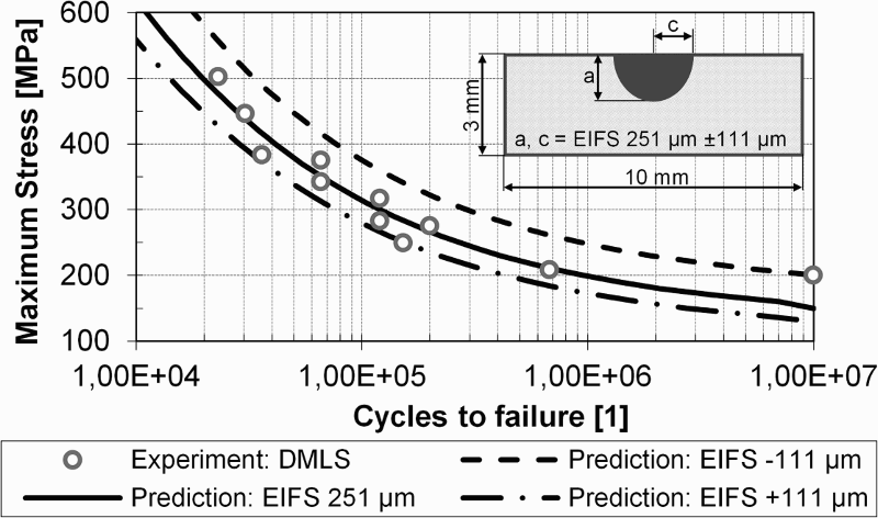
Description of experimental results for Ti–6Al–4V DMLS specimens based on an EIFS, R = 0.1, Kt = 1, heat treatment: 710°C/2 h
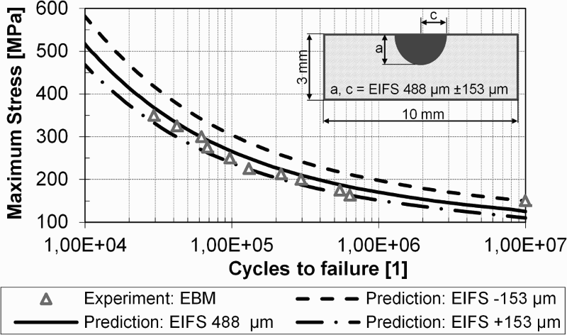
Description of experimental results for Ti–6Al–4V EBM specimens based on EIFS, R = 0.1, Kt = 1, heat treatment: 710°C/2 h
To estimate the influence of surface roughness on linear elastic fracture mechanics, an EIFS is calculated to capture both the experimental measurements and the scatter. The fatigue performance of the DMLS specimens can therefore be completely described by an EIFS of 251 μm ± 111 μm (Fig. 4), while an EIFS of 488 μm ± 153 μm describes the SN curve (including the scatter) for the EBM specimens (Fig. 5).
Figure 6 displays the resulting EIFS for different Rt. It has to be noted that this correlation is based on the averaged values of Fig. 4 (EIFS: 251 μm), Fig. 5 (EIFS: 488 μm), and results of HIP and milled specimens.
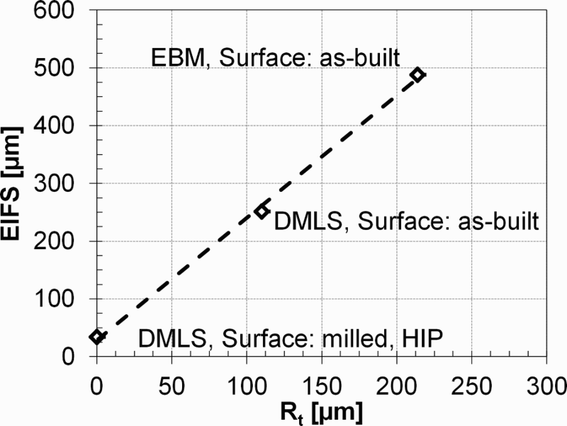
Calculation of EIFS from maximum height of profile (Rt)
HIPed DMLS material was used to reduce the size of (internal) defects, which can distract the influence of surface roughness on fatigue performance. Although the use of HIP tends toward a more coarse microstructure (which also has a subsequent impact on the fatigue performance), internal defects were deemed to be more critical.
Based on Fig. 6, estimations are made for SN curves with different surface roughness (Fig. 7) and compared with literature values.8,10,24 Fatigue crack growth curves of DMLS material (Fig. 3) are used as input for this estimations.
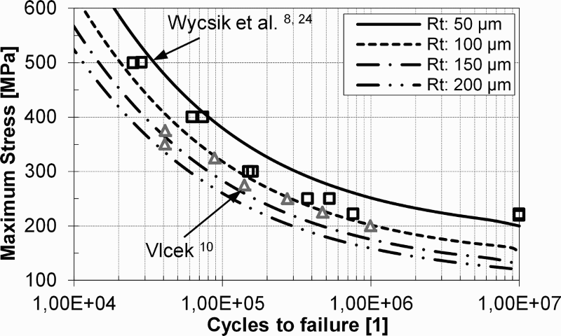
Wycisk et al.8,24 investigated the fatigue properties of as built, round, DMLS, Ti–6Al–4V specimens (Kt = 1), with an r ratio of 0.1. The specimens were subsequently heat treated at 650°C/3 h; a maximum surface roughness (Rt) of 90 μm was then determined. This experimental value is in accordance to the estimated range of Rt: 50–100 μm.
Vlcek 10 investigated the fatigue properties of as built, DMLS, Ti–6Al–4V. The round specimens (Kt = 1) were tumbled with ceramic stones to reduce the surface roughness (Rt = 165 μm) and hot isostatic pressed at 843°C/4 h/1000 bar. Fatigue properties were evaluated at an r ratio of 0.1. The estimation indicates a surface roughness of 100–200 μm (Rt).
It must be noted that the heat treatment of both literature data sets differs from the material investigated here. Therefore, the da/dN–ΔK curves of the literature data sets may be different.
Discussion
Tensile tests
Through comparison of the measured tensile properties, it can be seen that the EBM specimens demonstrate a slightly lower UTS and YS when compared to their DMLS counterparts. Several factors can have an influence on the results: process related defects can tend toward a reduced cross-section and therefore lower the tensile properties; chemical composition is a further important aspect that can lead to decreased tensile properties; indeed, it was noted that the strength improving 25 elements Al and O are reduced in the manufactured EBM specimens; microstructure and therefore build temperature and post-heat treatment can heavily influence the YS due to a coarsening of the microstructure, as reported by Filip et al., 26 for lamellar two-phase titanium alloys. Which of these factors are responsible for the lower tensile properties must be evaluated in detail in future studies.
Optimised EBM process parameters may help to avoid defects and evaporation of Al. 27 Additionally, chemical analysis of the powder could help to understand the influence of oxygen on the mechanical properties of additive manufactured Ti–6Al–4V as Gysler and Lütjering 28 reported for Ti–6Al–4V.
Fatigue crack growth
In the presence of large cracks, fatigue crack growth resistance can partly ascribed to the underlying microstructure, as reviewed by Lütjering and Williams. 29 Crack deflection due to roughness induced crack closure could be responsible for the increased resistance of crack growth near the threshold (R∼0.1).25,29
Similar conclusion can be made for the different crack growth behaviour of EBM and DMLS (Fig. 3). It is known from the literature that the microstructure of Ti–6Al–4V EBM material is generally coarser than that of DMLS material.5,30
Experimental high cycle fatigue properties
Although the fatigue behaviour of AM Ti–6Al–4V depends in general upon a number of mechanical, microstructural and chemical factors, 31 it seems that the presence of surface roughness, dependent on the process and powder used, is the dominant factor for the low fatigue performance of AM Ti–6Al–4V when compared to AM milled material. 32 This can also be concluded from the point of crack initiation, which starts from stress concentrations at the surface and not from defects or non-homogeneous microstructure.
It has to be noted that the influence of defects on the fatigue performance is only negligible to a certain size.
The lower fatigue limits of the EBM specimens can therefore be ascribed to the surface roughness, which tends toward higher stress concentrations, resulting in a lower fatigue limit when compared to the DMLS material. The determined experimental fatigue limits are in accordance with the recent literature for DMLS (Smax: 210 MPa 33 ) and EBM (Smax: 150 MPa 33 ) Ti–6Al–4V material.
Estimated high cycle fatigue properties
Both Figs. 4 and 5 indicate that, for un-notched specimens, the surface roughness effect can be described by a unique EIFS value using a fracture mechanics approach. A linear relationship between EIFS and Rt was used to successfully estimate SN data of additively manufactured Ti–6Al–4V.
Although these results appear promising, it has to be noted that the verification of the model is based only on small and un-notched specimens, solicited by constant amplitude loading. Therefore, more extensive validation with more realistic specimen designs (i.e. notched) and loading conditions (variable amplitude loading and multiaxial loading) must be undertaken in any future work.
Conclusions
Two different AM technologies have been investigated for comparison reasons. An experimental test programme was performed in order to determine the influence of surface roughness on fatigue performance of additive manufactured specimens. First insights in estimating the influence of surface roughness have been given and compared to literature data.
The following conclusions can be drawn:
High cycle fatigue properties are dominated by surface roughness (direct metal laser sintered specimens: Rt = 110 μm, electron beam melted specimens: Rt = 214 μm). The crack growth rate differs between electron beam melted and direct metal laser sintered specimens in the near threshold regime. Estimation of fatigue life based on an EIFS seems to be a suitable approach to estimate the influence of surface roughness on fatigue life.
Footnotes
Acknowledgement
The author would like to thank Vitus Holzinger, Christian Pander, Dieter Meixner, Martin Muir and Dr. Wolfgang von Bestenbostel for their support.