
Abstract
The plastic deformation of multiphase steels is described employing an irreversible thermodynamics formulation. Transformation induced plasticity and dual phase grades are described within a single theoretical framework. The approach describes the plastic deformation of each individual phase in terms of the evolution of dislocation density, subject to dissipative mechanisms associated to dislocation generation, glide and annihilation. The collective behaviour of the ensemble of phases into a single microstructure is ensured through a self-consistent approach based on the iso-work approximation. The parameterised model shows very good agreement with several alloys studied experimentally and available in the literature.
Keywords
Introduction
The initial microstructures in multiphase transformation induced plasticity (TRIP) assisted steels may contain four phases: ferrite, bainite, martensite and retained austenite, with the latter transforming into martensite through mechanical work. This mechanically induced martensitic transformation (MIMT) provides extra plasticity and extends the range for uniform elongation. The mechanism to activate MIMT depends on the stability of retained austenite, which can be quantified in terms of the temperature denoted as  .1,2 The martensitic transformation is stress induced when the service temperature is lower than
  . Above this temperature, however, the transformation is strain induced.
While the main characteristic of TRIP steels is the presence of the metastable austenite phase, other important phases in TRIP assisted steels include ferrite, which provides ductility; bainite, a mixture of bainitic ferrite and austenite films; and martensite, the strongest constituent of the system. As can be surmised by the multiphase nature of the typical microstructure in TRIP steels, their plastic deformation behaviour is the result of the interaction between all the constituent phases. To approach the mechanical properties of multiphase TRIP steels, several constitutive models3–7 have been proposed but these models are seldom formulated in terms of individual microstructural features responsible for the strengthening of individual phases.
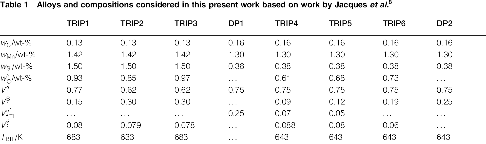
In our proposed approach, we explicitly consider the evolution of dislocation densities as the result of plastic deformation in each phase and take into account the effect of individual strengthening microstructural features—i.e. the characteristic length scales relevant to dislocation displacement—such as the subunit size of bainitic ferrite, the grain size of intercritical ferrite and martensite lath width. The model considers the MIMT of retained austenite and considers the influence of chemistry and processing conditions on the size of the subunit size of bainitic ferrite. To parameterise the models, we consider different multiphase steel alloys reported in the work by Jacques et al., 8 which are in turn listed in Table 1 —Jacques et al. 8 is one of the few works that report on the phase constitution of TRIP steels before mechanical deformation. One of the strengths of the present model is the fact that once the parameters have been identified, they can potentially be used to predict changes in the behaviour of the microstructure upon changes in composition or microstructure length scale, although the current parameterisation still presents significant uncertainties.
Alloys and compositions considered in this present work based on work by Jacques et al. 8
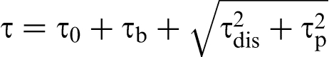
Irreversible thermodynamics modelling of plastic deformation
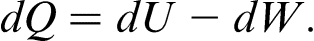
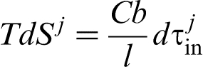
The model for the plastic deformation of the multiphase microstructure in TRIP steels begins by considering the plastic deformation of individual phases. According to previous studies9,10 under plastic deformation, the increase in thermal energy due to entropy production ( ) during the deformation process results from the change in energy in the system as a result of the creation, glide and annihilation of dislocations (
 ), as well as the thermal energy dissipated to the surroundings (
 )9,10:
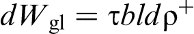
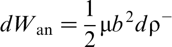
 incorporates contributions resulting from the work necessary for dislocation generation (
 ), glide (
 ) and annihilation (
 )
11
:
)
11
:

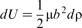
 results from the balance between the increase in internal energy (
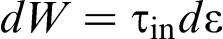
 ) due to the presence of dislocations—through their elastic energy contributions—and the external applied mechanical work (
 ):
):
 ,
,  ,
,  ,
,  and
and  are expressed as follows9,11:
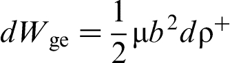
 ,
,  and
and  represent the shear modulus (of order 80 GPa), the magnitude of the Burgers vector (0.25 nm) and the strain.
  and
and  correspond to the change in dislocation density due to generation and annihilation.
The rate of dislocation annihilation is calculated from9,12:
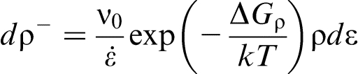
 stands for the strain rate and
  is the energy barrier for dislocation annihilation and is related to the strain rate and temperature.
12
is the energy barrier for dislocation annihilation and is related to the strain rate and temperature.
12
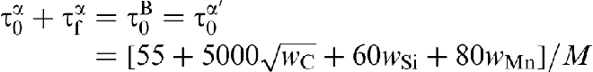
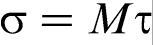
 stands for the shear stress, which is approximated as the summation of (i)
  , the Peierls stress and solid solution strengthening; (ii)
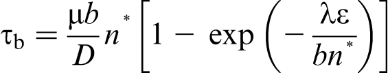
  , the back stress13,14; (iii)
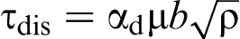
  , the stress field produced by dislocations15,16; and (iv)
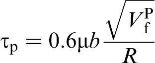
  , the precipitation hardening due to Orowan's effect,
14
which are in turn expressed as follows:
, the precipitation hardening due to Orowan's effect,
14
which are in turn expressed as follows:
 is adopted where
  indicates the hardening mechanism, whereas the superscript
  stands for the phases considered—i.e. ferrite, martensite, bainite, and austenite respectively.
 is estimated using the empirical relationships17–19:

 is adjusted based on the measured yield stress for the different alloys characterised by Jacques et al.
8
Because ferrite is the softest phase, its contribution to the strain hardening rate should be small, and deviations from the empirical formulas (equation (7) are dealt with by adjusting the parameter
is adjusted based on the measured yield stress for the different alloys characterised by Jacques et al.
8
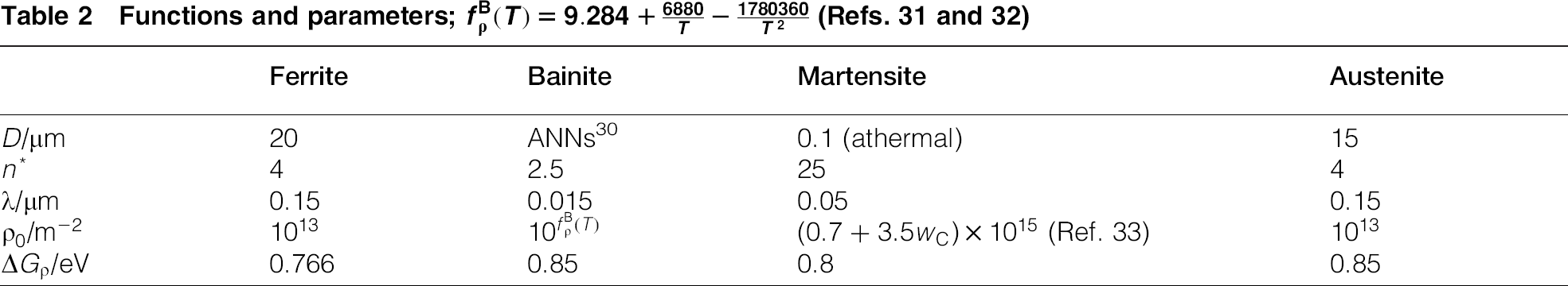
Because ferrite is the softest phase, its contribution to the strain hardening rate should be small, and deviations from the empirical formulas (equation (7) are dealt with by adjusting the parameter  . Expressions for the model parameters are listed in Table 2.
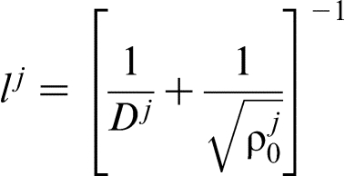
  stands for the characteristic length scale of the phase (CD) under consideration: grain sizes of polygonal ferrite and austenite, the lath width of martensite or the subunit size of bainitic ferrite.
  is the maximum number of dislocations piling up at the grain boundary of the corresponding phase, and
  is the average distance between slip planes.
  ,
,  and
and  are the numerical factor for the stress field due to dislocations (0.25), Taylor factor (3.06) and the atomic vibration frequency (of order
 ).
).
Functions and parameters; (Refs. 31 and 32
Invoking the ideas presented by previous studies9,10,20,16:
 is the rate of entropy increase during the irreversible process at room temperature,
  for steels
10
;
for steels
10
;  stands for the dislocation mean free path in phase
  .16,21
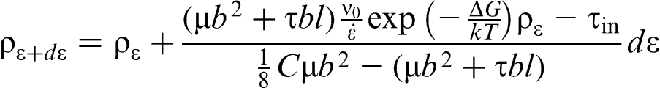
By combining equations (1)–(8)), the dislocation density as a function of plastic deformation can be updated in incremental strain steps, as follows:
Volume fraction evolution of mechanically induced martensite
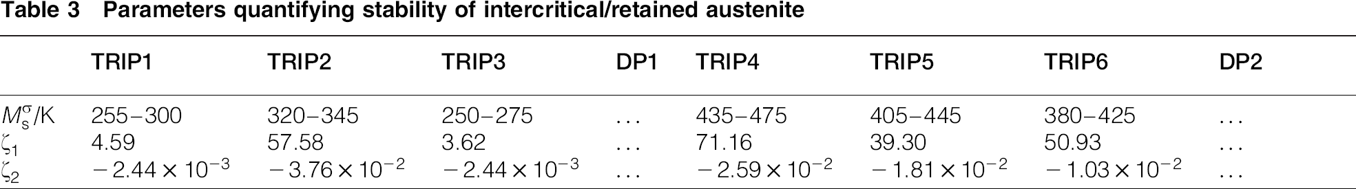
The stability of the retained austenite is accounted for by adopting the model by Ghosh and Olson,23,24 with  being estimated under para-equilibrium and thermodynamic equilibrium conditions between ferrite and the intercritical austenite. This parameter is listed in Table 3. At 300 K, the alloys denoted by TRIP2 and TRIP6 contain athermal martensite, indicating a martensite start temperature (
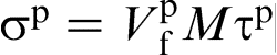 ) higher than room temperature for these alloys. TRIP4 and TRIP5, on the other hand, are under the stress induced mechanism, meaning that the service temperature—at which the deformation takes place—is above (
 ) but below
  . The alloys denoted as TRIP1 and TRIP3, on the other hand, underwent strain induced martensitic transformation.
Parameters quantifying stability of intercritical/retained austenite
In order to estimate the evolution of the martensite volume fraction as a function of plastic strain, Olson and Azrin
25
developed a model consisting of a linear function for the stress induced transformation, while a double exponential function was proposed for the strain induced transformation.
1
In order to approach both mechanisms, an exponential function is proposed:

 and
and  are assessed from a regression analysis and are reported in Table 3, and tested in Fig. 1.
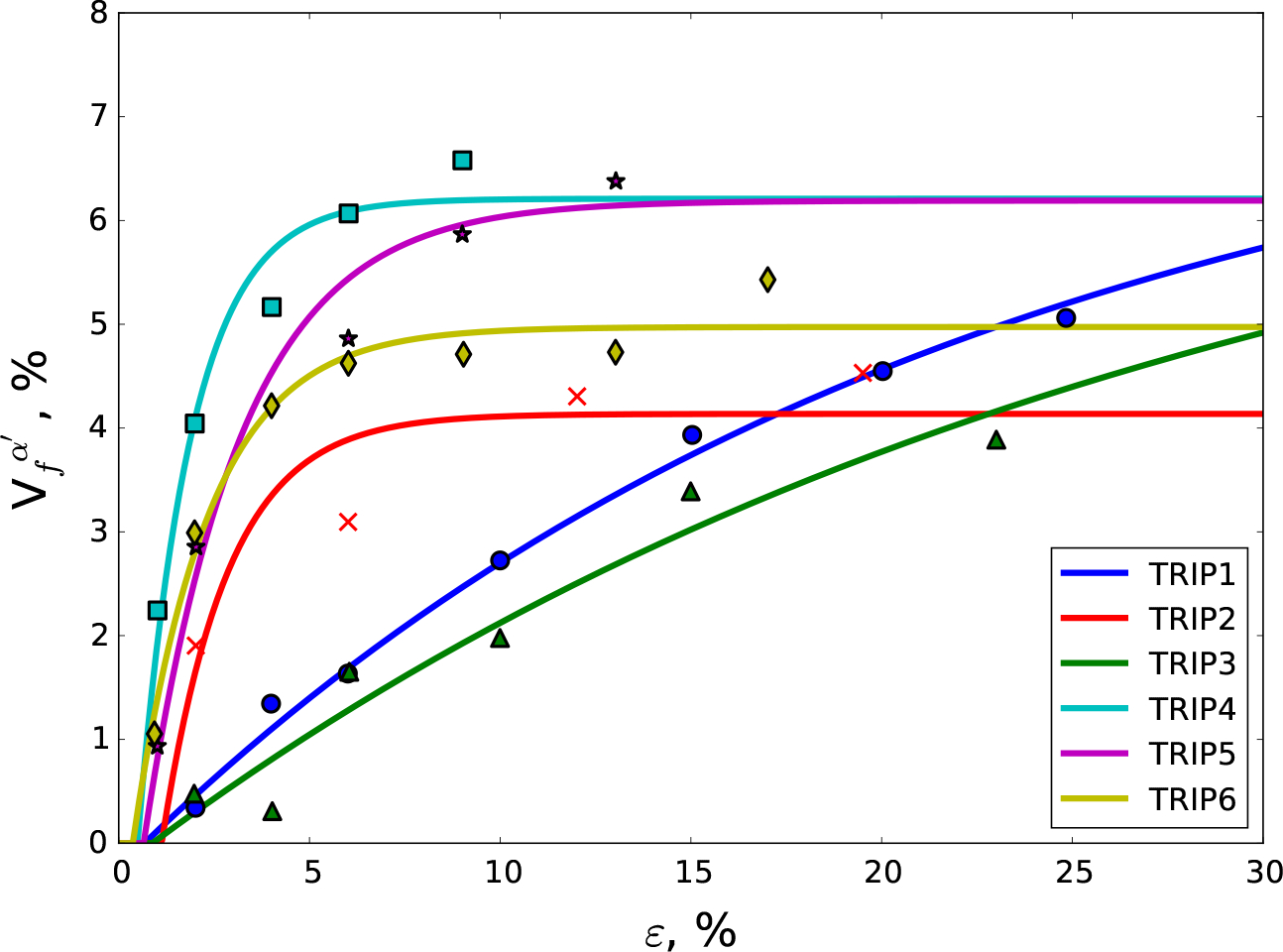
Volume fraction of mechanically induced martensite as function of plastic strain; points are experimental results obtained from Jacques et al. 8 ; curves are prediction using equation (10)
Calculation of subunit size of bainitic ferrite
In the absence of carbide phases, bainite is composed of bainitic ferrite plates, arranged in a layered structure between which austenite films are present. In bainite, the thickness fraction occupied by the austenite film is usually in the order of 0.12–0.15, with the films having typically a thickness of 30–50 nm.26–29 In this present work, the austenite films within ferrite sheaves are considered to act as strengthening precipitate phases. The bainitic ferrite plate thickness  , on the other hand, can have a wide range of values.
27
In order to estimate the plate thickness of bainitic ferrite, an artificial neural network (ANN) model is employed and trained using available experimental data.
30
This model requires three inputs: the temperature of the bainitic transformation (
, on the other hand, can have a wide range of values.
27
In order to estimate the plate thickness of bainitic ferrite, an artificial neural network (ANN) model is employed and trained using available experimental data.
30
This model requires three inputs: the temperature of the bainitic transformation ( ), the maximum driving force for nucleation of ferrite from an austenite matrix
  ) and the yield stress of the austenite at the isothermal holding temperature (
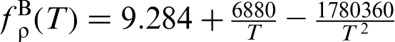 ).
).  and
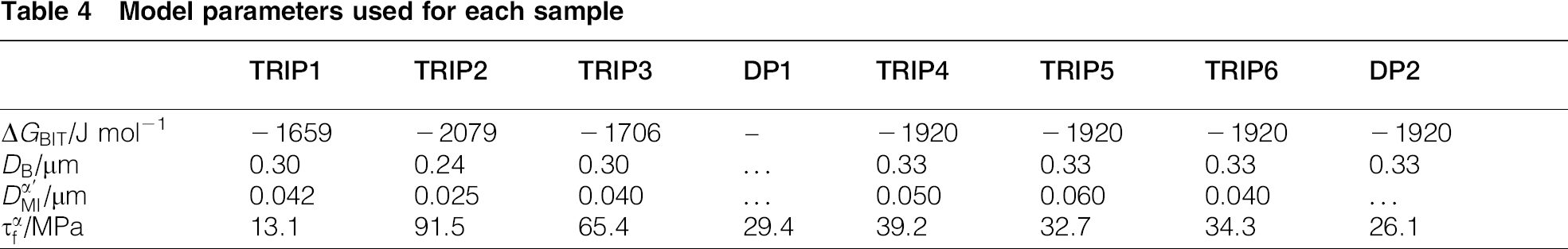
and  are listed in Table 4, where
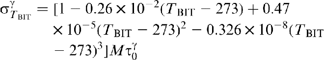
  are calculated using Thermocalc with the TCFE6 V6.2 database. The yield stress of austenite is estimated using equation (7), with the temperature effect according to previous studies19,30:
 using the ANN model is in the range 0.24–0.33 μm and is listed in Table 4.
Model parameters used for each sample
Results
Following equation 6equation 6) and using the iso-work approximation to ensure self-consistency, the progress of the TRIP effect is captured using  and
and  .
.  is calculated from equation (10), and
  is selected and listed in Table 4.
The results are shown in Fig. 2, where  stands for the normal stress calculated using
  . As can be seen in the figure, the calculations from the model presented in this present work agree rather well with the experimental results, except for the alloy denoted as DP2. The agreement is remarkable given the fact that only two parameters were adjusted to match the experimental results, with one parameter corresponding to the initial stages of the deformation, and the other one corresponding to the response of the system considering mechanically induced transformation of austenite into martensite.
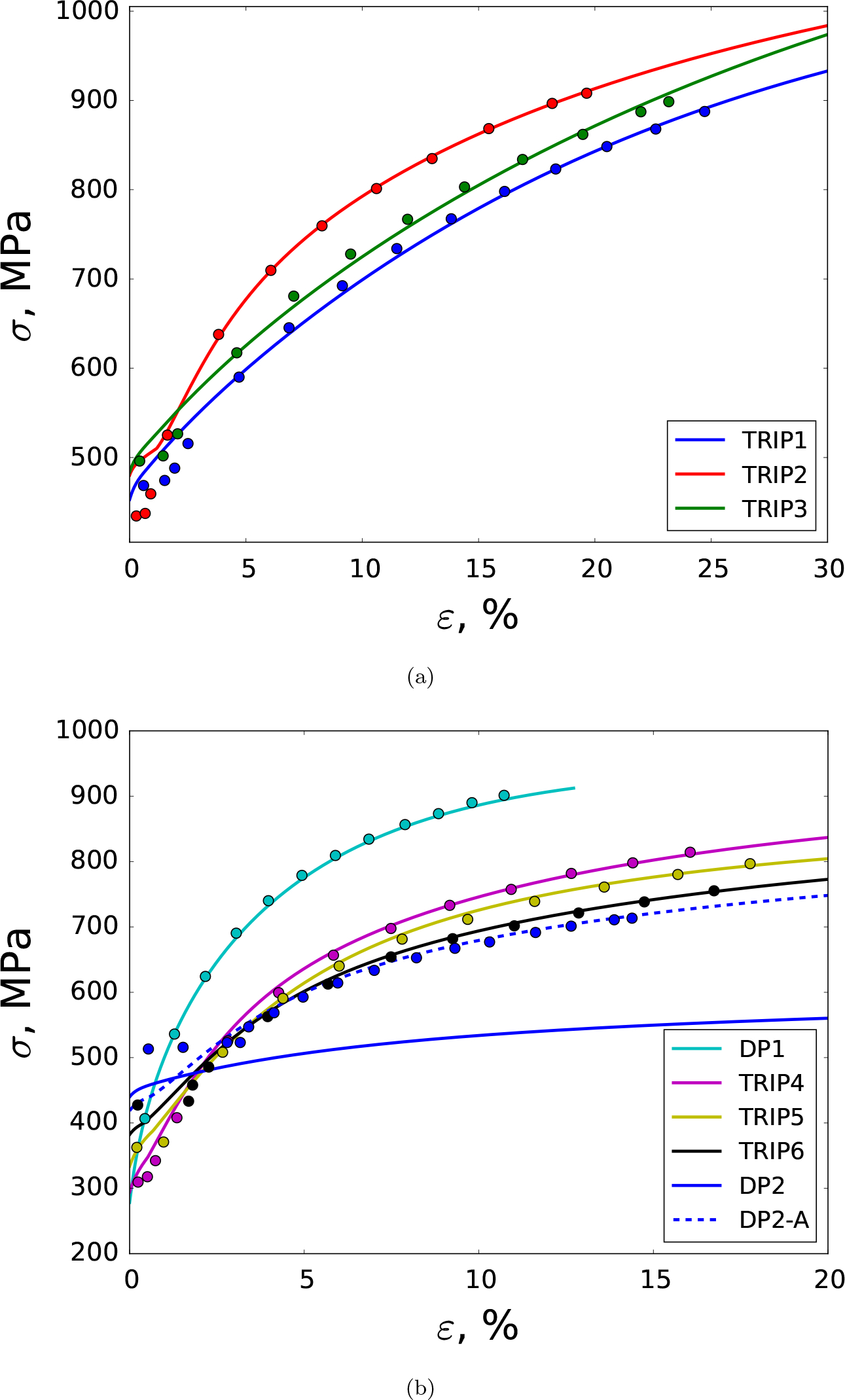
True stress–strain curves of multiphase steels; experimental points are obtained from Jacques et al. 8
In the case of DP2, we note that, according to Jacques et al.,
8
the initial microstructure contains only ferrite and bainite. The failure of the model may be due to inadequate parameterisation, although since the DP2 alloy does not have any retained austenite, the model only has one adjustable parameter, which only adjusts the initial yield point of the material. An alternative explanation for the discrepancy may be the fact that the actual phase constitution for DP2 does not correspond to the one reported by Jacques et al.
8
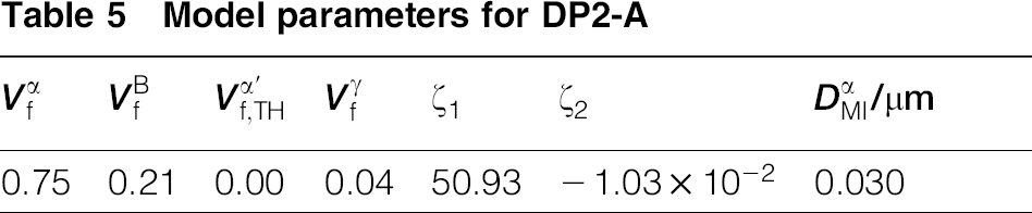
We thus constructed an alternative phase constitution set (denoted as DP2-A), where we assumed the presence of 4 of retained austenite. For DP2-A, we assume that the parameters of  and
and  of DP2-A are the same as those for TRIP6 in Table 5, given the very similar compositions and phase fractions. Figure 2 shows that under the assumption of the presence of (undetected) retained austenite, the model predictions for the DP2-A configuration agree much better with experiments. One must be careful, however, to point out that the extreme sensitivity of the model to the presence of retained austenite calls for a much more comprehensive analysis.
Model parameters for DP2-A


 /μm
/μmIn order to understand the stress contributions from each phase, we proceeded to calculate the stress–strain responses—Fig. 3—in TRIP4.  stands for the actual contribution from phase
  . Figure 3a shows that beyond 10 deformation, the strain hardening is dominated by
  , which represents a measure of the TRIP effect. To analyse the strengthening source, it is shown in Fig. 3b that
  in martensite is the key mechanism, which is controlled in turn by
  , according to equation (6b).
  is the characteristic length scale for dislocation evolution within martensite, which is related to the martensite lath width. The sensitivity of the mechanical response of TRIP microstructures to this parameter is evident from the variation in
  for the different alloys, as shown in Table 4, and it implies that the predictive ability of the present model is somewhat limited and we should consider the effects of temperature and initial size of austenite parent phase.

Calculations of TRIP4: a stress–strain correlations of each phase; b contribution from each mechanism to
Summary
In this present work, we employed the formalism of irreversible thermodynamics of plastic deformation to describe the deformation behaviour of multiphase steels. The model was applied to different TRIP alloys with varying amounts of ferrite, intercritical austenite, bainitic ferrite, film austenite and martensite. The iso-work approximation was used to account for the coupled, simultaneous plastic deformation of all the different phases in the microstructure. To account for the TRIP effect, the Olson–Cohen model for MIMT was incorporated into the model. The combination of all these models, with minimal post hoc adjustments, is shown to be able to describe the mechanical response (specifically strain hardening behaviour) in a range of microstructures with different phase constitutions. While preliminary, these results indicated that the models are capable of capturing much of the complex physical phenomena responsible for plastic deformation in complex multiphase steel microstructures.
Acknowledgements
R.A. would like to acknowledge the partial support of the U.S. National Science Foundation (grant nos. NSF-CMMI-0900187 and 095398). P.E.J.R. is grateful to Professor Mark Blamire for the provision of lab facilities.