
Abstract
Electronic waste (WEEE) is being generated at a rapidly increasing rate and leading to the removal of scarce and valuable metals from the materials cycle. The search for efficient WEEE reprocessing methods requires reliable data on the distribution of these valuable metals during smelting. In this work the distribution ratio of indium between FeOx–CaO–SiO2 slags and copper was examined at an oxygen partial pressure of 10−8 MPa (10−7 atm) and at 1300°C. The indium distribution ratio was strongly dependant on the CaO content, decreasing as the CaO content increased, but relatively unaffected by the Fe/SiO2 ratio of the slag over the range examined. Indium was inferred to be present in slag as InO1·5. The activity coefficient of InO1·5 was calculated and presented as iso-activity coefficient curves on the copper-saturated FeOx–CaO–SiO2 phase diagram. Volatilisation of indium under the oxidising conditions used in this work was insignificant, and it was shown that this is consistent with theoretical expectations. Only in much lower oxygen partial pressure environments can indium volatilisation be expected.
Introduction
High demand for electrical products has increased global sales such that the production of electrical and electronic equipment is one of the fastest growing business sectors in Europe (Cui and Forssberg, 2003). Rapid innovation is, however, making the lifespan of these products shorter and the rate of their disposal is rapidly increasing. A variety of terms are used to describe electronic waste. WEEE, an acronym for Waste Electric and Electronic Equipment, is used in the European Union to encompass electronic equipment, televisions and white goods such as ovens and refrigerators, while in North America the term e-waste is used and is more limited by not including large household goods. E-scrap describes the valuable metal containing fraction of WEEE/e-waste obtained by separation methods and which is sold to specialised smelters for processing (Lehner, 2011).
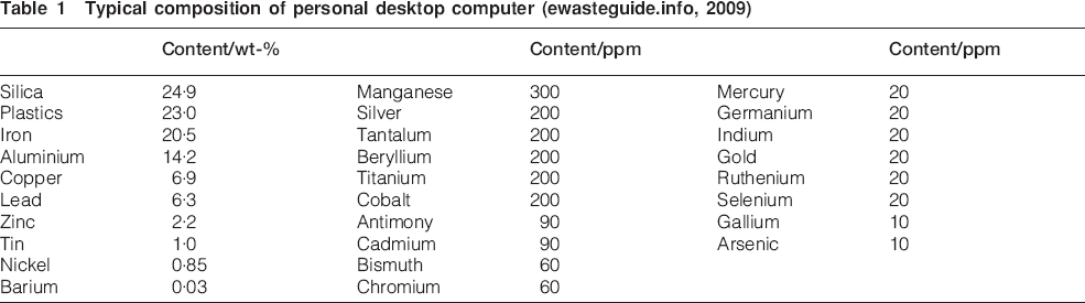
WEEE is a heterogeneous combination of non-metallic and metallic materials which changes in average composition from source to source over relatively short time periods. Typically a half of the mass of WEEE is steel and about 13 wt-% is a large variety of non-ferrous metals which can be divided into valuable metals (e.g. copper, gold, silver, platinum, tin, and indium) and hazardous metals (e.g. lead, cadmium, arsenic, and mercury). The greatest variety of elements is in computers and a typical composition of personal computers is given in Table 1 as an illustration (ewasteguide.info, 2009). Cui and Zhang (2008) list typical composition data for many other sub-categories of electronic scrap, but only for five major metals and three minor valuable metals. They make the important point that the key economic driver for reprocessing WEEE is the recovery of the valuable minor metals.
Typical composition of personal desktop computer (ewasteguide.info, 2009)
Indium in WEEE
Indium is a minor component of particular interest. The annual production of indium was only 640 tonnes in 2011, with a little over half being sourced from China (USGS, 2012). Historically the price of indium has been unstable, having rapidly increased around 2004 to about US$1000/kg but then falling back to about US$550/kg in 2012 (SMG, 2012).
Flat-screen displays consume about 80% of global indium supplies (Matharu and Wu, 2009). Flat screens contain a very thin transparent, conductive and heat resistant film of indium tin oxide (ITO), which consists of 90 wt-%InO1·5 and 10 wt-%SnO2. They typically require ∼700 mg of indium per square metre of screen surface, so a computer screen will contain about 0·5 g of indium (Buchert et al., 2012).
Indium was identified by the European Commission in 2010 as one of 14 critical materials whose continued supply was under threat, together with cobalt, gallium, germanium, the platinum group metals, the rare earths and tantalum (Buchert et al., 2012). It is believed by some that the supply of indium will not keep pace with demand, and that primary indium could be exhausted as early as 2025 unless replacement materials are found (Matharu and Wu, 2009). However, Mikolajczak (2009) considered that the world would not run out of indium, based on her analysis of mining reserves, continuing exploration, residue reserves and improvements in processing technology.
WEEE reprocessing
Landfilling close to the source of the waste is the cheapest method of WEEE disposal, but has a negative impact on the environment from the leaching of harmful substances into the water table. It also results in the dispersal of the valuable elements in WEEE in a form which makes their recovery almost impossible, analogous to a very complex orebody in the urban mine, i.e. the landfill site (Reuter, 2005; UNEP, 2013). Many countries now mandate the collection and recycling of WEEE, e.g. the European Community issued a directive 2002/96/EC on WEEE which became law in February 2003 and was subsequently recast in 2012 (European Commission, 2012).
Recycling of WEEE requires dismantling and mechanical separation to liberate and concentrate the valuable metals, and to remove and safely treat hazardous substances (Hagelüken and Kerckhoven, 2006). However, the recovery of valuable metals from WEEE is made difficult by several complicating factors (Hagelüken, 2007; Reuter et al., 2013) which impact especially on the minor valuable elements like indium. Electronic equipment is very complex, with many valuable and hazardous elements closely interlinked in numerous subsystems. The minor valuable elements are also present in very dilute form, making recovery both technically difficult and incomplete. The losses associated with these minor elements must be offset by the profits from the recovery of other metals in WEEE, which implies that WEEE reprocessing must take place in an integrated facilty which aims to recover a wide variety of metals. Product design also affects the recovery of metals from WEEE, where the distribution of valuable metals in widely distributed components makes their physical separation almost impossible and so further exacerbates the dilution problem. Hagelüken (2007) highlights this difficulty with reference to the many electronic systems in modern cars. They are so dispersed throughout the car body that they are rarely able to be separated before bulk shredding.
WEEE reprocessing is dominated by pyrometallurgical methods (Antrekowitsch et al., 2006). Integrated non-ferrous metals smelters take the copper/lead fractions, circuit boards, and other fractions containing precious metals which have been separated from WEEE (UNEP, 2013). Copper smelters produce much less toxic emissions than lead smelters and so can be safely sited near the population centres, therefore minimising the costs associated with transporting WEEE.
An attractive reprocessing route is via black copper smelting, such as is practiced at Montanwerke Brixlegg in Austria (Woerz and Wallner, 1988). Black copper smelters accept both metallic copper scrap and oxidic drosses and reduce them with carbon to impure black copper, followed by oxidation of the black copper to remove many of the impurities. A typical flowsheet with a reductive first stage is shown in Fig. 1. Reduction often takes place in a blast furnace, although top submerged lance (TSL) reactors are being introduced e.g. at Aurubis’ Lünen site (Aurubis, 2013) and LS Nikko's facility in Danyang, Korea (Wood et al., 2011). In the second stage, oxygen enriched air is blown through the molten copper in a Peirce–Smith converter and the impurities undergo oxidation. At Lünen a top blown rotary converter is used to oxidise tin and lead to slag (Aurubis, 2013). Another flowsheet configuration is to operate with an oxidising first stage in a TSL reactor followed by reductive slag cleaning in a blast furnace, such as at Hoboken (Hagelüken, 2005). Finally, both stages can be performed consecutively in a single TSL reactor such as by Dowa Mining in Kosaka (Wood et al., 2011).
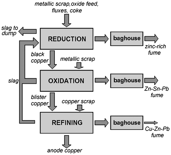
Simplified flowsheet of a black copper smelter (after Anindya et al., 2009)
No quantitative information on the deportment of indium to the various phases during secondary copper smelting using the black copper route could be found in the literature.
An important factor in determining the recoveries of valuable metals is the way in which they distribute between the black copper and the FeOx–CaO–SiO2 slag during both stages. These distributions are affected by the composition of the slag, which provides potential for controlling the recovery of valuable elements from WEEE. However, the distribution behaviour of many of the metals in WEEE is not well known because these elements are not often found in copper ores. Indium is an example of such an element. Most indium is found in zinc deposits as a solid solution in sphalerite (ZnS) at concentrations from 10–20 ppm (Alfantazi and Moskalyk, 2003). Indium bearing waste streams from zinc processing are typically sent to lead smelters for treatment so the few reports on indium distribution in the literature relate only to lead/slag systems.
In this work the distribution of indium between copper and FeOx–CaO–SiO2 slags will be examined under copper converting conditions.
Distribution thermodynamics
The distribution of a minor element between molten metal and slag can be described by the following reaction


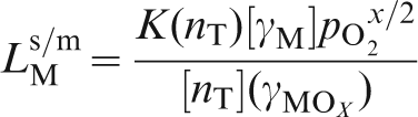
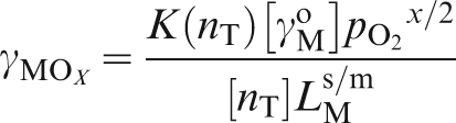
Yazawa (1994) showed that the distribution ratio can be expressed as
 is the oxygen partial pressure.
If the concentrations of M in the metal and MOx in the slag are low, their activity coefficients can be assumed to be constant, so all terms in equation (3), except the oxygen partial pressure, are constant and it follows that

 will be a straight line whose slope is x/2 and so the oxidation state of M, and so the identity of MOx, can be inferred. Furthermore, if the activity of M (γM) in the metal phase is known then the activity coefficient of MOx in the slag (γMOx) can be calculated using equation (3).
Indium distribution data
There are four reports in the literature on the distribution of indium between slag and molten metal, but none of them involved copper as the metallic phase. Lead was the molten metal in three studies, while pure molten indium was used in the fourth study.
The first reported study is that of Johnson et al. (1983) from the US Bureau of Mines. The temperature was 1200°C but they used a fixed oxygen partial pressure of 10−13 MPa (10−12 atm) so the oxide form of indium in the slag cannot be evaluated from their data. They found that the indium slag/metal distribution ratio was independent of the Fe/SiO2 ratio of the slag but decreased with increasing basicity, defined as (wt-%CaO+wt-%MgO)/wt-%SiO2.
Hoang and Swinbourne (2007) determined the indium distribution ratio between molten lead and CaO–SiO2–FeOx slags at 1200°C and oxygen partial pressures from 10−13 to 10−11 MPa (10−12 to 10−10 atm). Alumina crucibles were used so the slags contained about 8 wt-%Al2O3. They proposed that indium was present in slag as In2+, i.e. as InO, based on the slope of the best fit line on a graph of the form indicated by equation (4). The range of oxygen partial pressures examined was small, leading to uncertainty in this conclusion. The indium distribution ratio was observed to be independent of the CaO/SiO2 ratio of the slag, but dependent on the FeO/SiO2 ratio, as shown on Fig. 2.
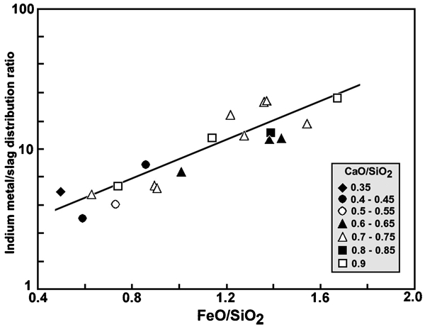
Indium metal/slag distribution ratio for molten lead as function of slag composition at 1200°C (Hoang and Swinbourne, 2007)
Henao et al. (2010) criticised the technique used by Hoang and Swinbourne and developed a method to analyse the slag that was claimed to offer an improvement in the accuracy of the results. The slag was analysed by electron probe X-ray microanalysis (EPMA) so that systematic errors due to lead entrainment could be avoided. They determined the indium distribution ratio between lead and CaO–SiO2–FeOx slag at 1200°C over oxygen partial pressures from 10−13 to 10−9 MPa (10−12 to 10−8 atm). Their data suggested that indium is present in slag as In3+ i.e. as InO1·5. They also reported that there was insignificant volatilisation of indium during the experiments and that indium distribution is a strong function of temperature, with higher temperatures favouring indium partition to the lead.
The data of all three studies are compared on Fig. 3. They do not differ much, within experimental errors, at the lower oxygen partial pressures but diverge at the higher oxygen partial pressures.
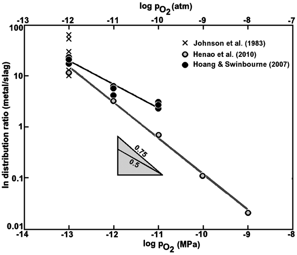
Published data for indium distribution as function of oxygen partial pressure
Ko and Park (2011) investigated the behaviour of indium in CaO–SiO2–Al2O3 slags at a higher temperature of 1500°C and a much lower oxygen partial pressure 10−18 to 10−17 MPa (10−17 to 10−16 atm) than the previous studies. They equilibrated the slag with pure indium metal in graphite crucibles. They concluded that indium was present in CaO–SiO2–Al2O3 slag under such very reducing conditions as In+ i.e. InO0·5. The experimental conditions are relevant to iron blast furnace smelting, but not to copper converting.
All of the reported work was conducted at oxygen partial pressures that are appropriate to the reduction stage of black copper smelting, but not to those prevailing during copper converting. Hoang and Swinbourne (2007) and Henao et al. (2010) are in conflict regarding the nature of the indium species in slag, although the much wider range of oxygen partial pressures employed by Henao et al. (2010) favours their conclusion.
Phase equilibria of FCS slags
Ferrous calcium silicate slags in equilibrium with molten copper belong to the FeOx–CaO–SiO2–Cu2O system where x has a value between 1·0 and 1·5 depending on the oxygen partial pressure and temperature. Kongoli et al. (2006) used proprietary software owned by FLOGEN Technologies to predict the phase equilibria in this system at 1300°C and presented their data on rectangular coordinates using CaO (wt-%) and Fe/SiO2 (w/w) as the axes. The phase equilibrium diagram for FCS slags is given as Fig. 4, with the predicted phase boundaries at oxygen partial pressures of 10−7, 10−8 and 10−9 MPa (10−6, 10−7 and 10−8 atm).
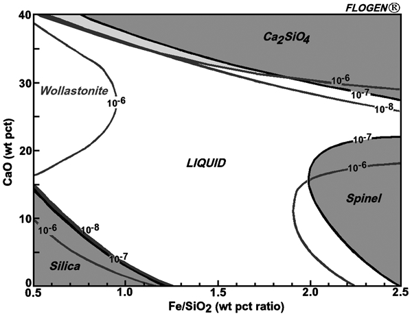
Liquid region for slags is copper saturated FeOx–CaO–SiO2 system as function of oxygen partial pressure (in MPa) at 1300°C (Kongoli et al., 2006)
Method
The three-phase equilibration method was used, where slag and copper are equilibrated with a gas of known oxygen partial pressure. Two sets of experiments were conducted; either InO1·5 was initially added to the slag or indium was added to the copper. Greater confidence that true equilibrium had been achieved was provided by approaching equilibrium from both directions.
Master slags of the required Fe/SiO2 ratio and CaO content were prepared from powdered Fe3O4, calcined CaCO3, and finely ground quartz glass. They were mixed in a ring grinder then premelted in a high density MgO crucible in contact with copper at 1300°C under the oxygen partial pressure to be used in the experiments. After a minimum of 6 h the crucible was removed from the furnace and broken up to recover the slag. The master slag was ground in a ring mill. A copper–5 wt-% indium master alloy was prepared by melting indium and high conductivity copper wire under nitrogen at 1300°C.
Slags with CaO contents close to the dicalcium silicate phase boundary expanded during cooling, broke the MgO crucible and crumbled to a powder. This is a well known phenomenon (Juckes, 2002), in which a 12% volume expansion occurs as the transformation to γ-Ca2SiO4 takes place. Slags with a high target Fe/SiO2 ratio exchanged iron oxides with MgO, lowering the Fe/SiO2 ratio and resulting in a MgO content of 5–8 wt-% so slags with a Fe/SiO2 (w/w) greater than 1·4 could not be prepared. The MgO crucible was replaced by an alumina crucible coated with a fired Cr2O3 coating, and then a zirconia crucible, but both failed catastrophically during melting. Platinum could not be used because it would have been attacked by the molten copper.
All experiments were conducted in a vertical tube furnace fitted with Pt/Pt–13 wt-%Rh thermocouples for temperature measurement and control. Slag and alloy were contained in 5 cm3 high density MgO crucibles. Crucibles were supported in the furnace on a closed-end alumina tube fitted with a thermocouple, as shown in Fig. 5.
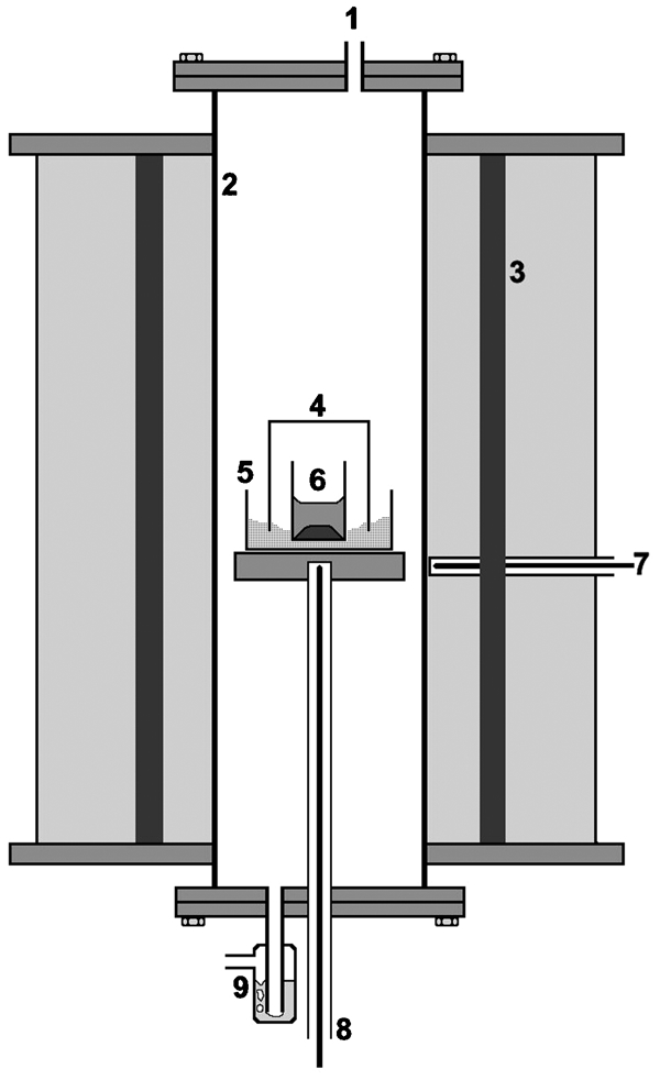
Furnace arrangement (not to scale): 1, gas inlet; 2, recrystallised alumina tube; 3, silicon carbide elements; 4, alumina crucible; 5, alumina tray filled with alumina powder; 6, magnesia sample crucible; 7, control thermocouple; 8, sample thermocouple; 9, dibutyl phthalate bubbler
Henao et al. (2010) found that indium volatilisation was not significant, although indium is known to volatilise as both In(g) and In2O(g) (Valderraman and Jacob, 1977). Nevertheless, the sample crucible was covered by an inverted alumina crucible set in a bed of alumina powder as a precaution against volatilisation. Indium mass balances subsequently confirmed that the amount of indium lost from the covered crucibles during equilibration experiments was negligible.
The total gas flowrate was 400 cm3 min−1 to prevent thermal segregation in the hot furnace tube, and the oxygen partial pressure was controlled by a CO/CO2/N2 gas mixture. Individual gas flow rates were controlled by mass flow controllers, and each gas was passed through oxygen and moisture molecular sieve towers. A bubbler containing dibutyl phthalate prevented back-diffusion of oxygen into the furnace. A zirconia ceramic electrolyte oxygen probe was used to confirm the oxygen partial pressure inside the furnace.
Approximately 5 g of slag and 5 g of copper were placed into a magnesia crucible, together with either enough InO1·5 or Cu–In master alloy to provide a concentration of 1 wt-%In in the slag or copper respectively. The MgO crucible was covered with an inverted alumina crucible and raised into the hot zone of the furnace, which was slowly heated to 1300°C then held for times up to 16 h. The crucible assembly was then lowered into the cooler zone of the furnace and removed, broken up and the copper and slag carefully separated from each other. The slag was ground in a ring mill then sieved to remove flattened entrained copper flakes. Slag samples were fused with sodium peroxide then dissolved in hydrochloric acid prior to analysis using inductively-coupled plasma atomic emission spectrometry (ICP-AES). A file was used to clean the copper of any adhering slag, then the copper button was sampled by drilling several small holes at random. The copper was dissolved in aqua regia then analysed for indium using ICP-AES.
The absolute error in both the indium and copper analyses was ±0·02 wt-%. This, combined with errors due to the temperature and oxygen partial pressure, led to an estimated average relative error of ±20% in the indium distribution ratio. The relative error is large because the indium content of the copper is small. The relative error in the copper distribution ratio was estimated at ±5% because the copper content of the slags was much higher than their indium content.
Results and Discussion
All slags contained magnesia as a result of attack on the crucible, the average MgO content being 6·5 wt-%. All slag analyses were therefore normalised to exclude magnesia. This procedure increased the CaO content by a factor of 1·07, but had no affect on the Fe/SiO2 ratio and an insignificant effect on the indium content.
Equilibration time
The minimum time required to reach equilibrium was determined by contacting a slag having a Fe/SiO2 (w/w) ratio of 1·2 and a normalised CaO content of 19·7 wt-% with copper at times varying up to 16 h. The oxygen partial pressure was 10−8 MPa (10−7 atm) and the temperature was 1300°C. Equilibrium was achieved after 6 h of contact, as can be seen on Fig. 6. Experiments where indium was initially in copper produced less scatter so the results of such experiments were given more weight whenever there was conflict in data sets.
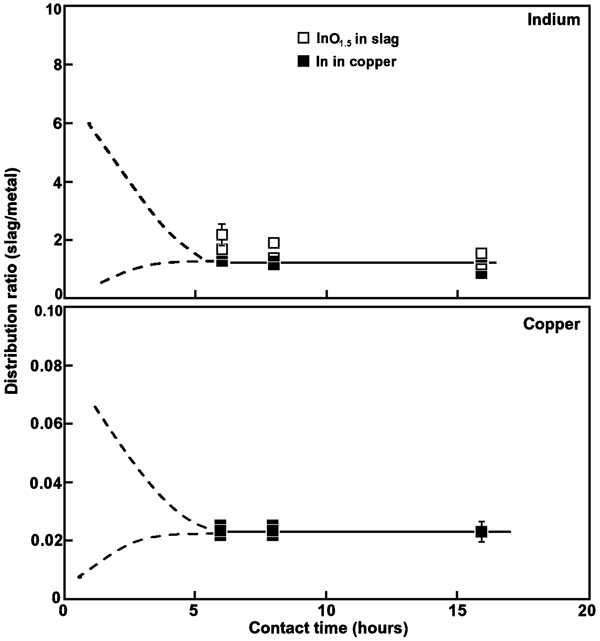
Distribution ratio (slag/metal) of indium and copper as function of contact time at oxygen partial pressure of 10−8 MPa (10−7 atm) at 1300°C
The average copper content of the slag for all experiments shown on Fig. 6 was 2·3±0·15 wt-%. Yazawa et al. (1999) reported copper contents in the range 2 to 3 wt-% for slags of similar composition, which provides confirmation of the results of this work.
Effect of oxygen partial pressure
Two series of experiments were performed, both at essentially the same Fe/SiO2 ratio but at different normalised CaO contents. The results are given in Fig. 7. There is a considerable degree of scatter in the data so the relative error is large, especially at the highest oxygen partial pressure. The range of oxygen partial pressures examined is also limited and this increases uncertainty. The mean slope of the best fit line through the data is close to 0·5, as expected when indium is present in the slag as In2+, and fits less well to a line of slope 0·75, as is expected when indium is present as In3+.
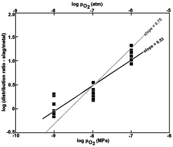
Logarithm of distribution ratio (slag/metal) of indium as function of logarithm of oxygen partial pressure at 1300°C
There are reasons, however, for believing that indium is much more likely to exist in slag as In3+ than as In2+. Divalent indium is not believed to be stable, even in aqueous solution (Cotton and Wilkinson, 1972). The gaseous species InO(g) is also very unstable as shown by the Gibbs free energy change for the formation reaction

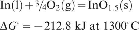
It is concluded that indium is most likely to be present in slag as In3+ i.e. InO1·5, which supports the previous findings of Henao et al. (2010).
Indium distribution ratio as a function of slag composition
Owing to the previously mentioned difficulties in controlling the slag composition, the range of Fe/SiO2 (w/w) ratios was limited to 0·74 to 1·2 and the maximum normalised CaO content to 30 wt-%. The oxygen partial pressure employed was 1×10⁻⁸ MPa (1×10⁻⁷ atm). The copper content of the slag was also determined by analysis so both the indium and copper distribution ratios could be determined
The previous results of Takeda et al. (1983) for the activity coefficients of SnO and CuO0·5, and therefore the distribution ratios, were almost independent of the Fe/SiO2 ratio. As a result, it was hypothesised that the indium distribution ratio would also be independent of the Fe/SiO2 ratio. The distribution data for indium and copper were therefore plotted in the form shown in Fig. 8.
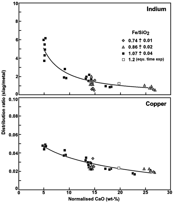
Distribution ratios (slag/metal) of indium and copper as function of Fe/SiO2 (w/w) ratio and normalised CaO content at 1300°C
The data for all Fe/SiO2 ratios group around the same best fit lines, although the scatter around the best fit line for indium is large due to the large relative error. It is worst at a CaO content of approximately 15 wt-% where one group of data points, all from one batch of master slag, are well below the best fit line. No reason could be found to account for this so the data was accepted and shown in Fig. 8. Curves were found to be a much better fit to the data than straight lines. These results support the hypothesis that the indium and copper distribution ratios are, within experimental error, independent of the Fe/SiO2 ratio of the slag.
The finding in this work that the value of the indium distribution ratio is independent of the Fe/SiO2 ratio of the slag is generally in accord with the results presented by Takeda et al. (1983) for both SnO(l) and CuO0·5(l) in ferrous calcium silicate slags. They are, however, contrary to the results presented by Hoang and Swinbourne (2007) where the indium distribution between molten lead and slag was reported to be a function of the FeO/SiO2 ratio. The oxygen partial pressures used in the work by Hoang and Swinbourne (2007) were much more reducing than those employed in this work, but it is not apparent that this could be a reason for the difference.
Activity coefficient of InO1·5(s)
The activity coefficient of InO1·5(s) in slag can be derived from the values of the distribution ratio using a rearranged form of equation (3)
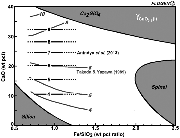
Values of the limiting activity coefficient of indium, γo In(l) in liquid copper found in the literature are listed in Table 2. Most were estimated from activity/composition graphs given by the authors.
Reported values of limiting activity coefficient of indium in copper
Sigworth and Elliott (1974) provided no information on the method used to obtain their reported value. Azakami and Yazawa (1976) used a cell containing prefused electrolyte and copper–indium alloy heated to temperatures from 700 to 1000°C. The cell electromotive force was measured every 5 min until it stabilised. The activity of indium in the alloy was calculated and from that the activity coefficient. They extrapolated their data to 1200°C to give a value of 0·32 but unfortunately the extrapolation method was not described so a value at 1300°C cannot be calculated. Kang et al. (1977) also used an electromotive force method and derived a value of ∼0·12 at 1100°C. They also quoted an unpublished report by Valderrama and Alcock (1977) in which the limiting activity coefficient is ∼0·5 at 1100°C but no information was provided on the experimental method used. Kellogg (1991) used a non-ideal associated species model to correlate the Kang et al. data and predicted an activity coefficient of approximately 0·25 at 1127°C, and that the value of the limiting activity coefficient was little affected by temperature.
There is clearly no firm consensus in the literature, although the values are of similar magnitude. That of Azakami and Yazawa (1976) is between the higher and lower published values and was accepted in this work. The value of the limiting activity coefficient was further assumed to remain unchanged at 1300°C, based on the finding of Kellogg (1991).
Substituting all values into equation (3), it follows that
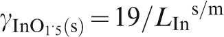
Iso-limiting activity coefficient lines for InO1·5(s) in copper saturated FeOx–CaO–SiO2 system at 1300°C
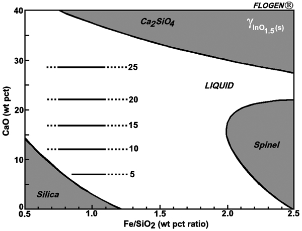
The activity coefficient values in Fig. 9 are similar in magnitude to those for CuO0·5 found both by Anindya et al. (2013) in similar work on tin distribution during WEEE smelting and by Takeda and Yazawa (1989) as shown in Fig. 10, although they increase in value more quickly as the CaO content of the slags increases. This similarity in behaviour provides further support for the proposal that indium exists in slags as InO1·5 under the conditions of oxygen partial pressure and temperature used in this work.
Iso-limiting activity coefficient lines for CuO0·5(l) in copper saturated FeOx–CaO–SiO2 system at 1300°C: Anindya et al. (2013) black lines and Takeda and Yazawa (1989) grey lines
Acid base nature of InO1·5
The strong similarity in the distribution behavior of both indium and copper as a function of the CaO content and Fe/SiO2 (w/w) ratio of FCS slags implies that InO1·5 is a neutral metal oxide, as is CuO0·5 (Yazawa, 1994).
There are fundamental reasons for believing that InO1·5 behaves as a neutral metal oxide. Gilchrist (1989) related the acid-base nature of metal oxides to two properties of the bond between the metal cation and the oxide anion. The electrostatic bond strength, as indicated by the ratio ‘z/a2’ where ‘z’ is the charge on the cation and ‘a’ is the sum of the ionic radii of both ions (in Ångstrom units), typically lies between 0·4 and 0·9 for neutral metal oxides. The ionic radii for O2− and In3+ are 1·4 Å and 0·8 Å respectively (CRC Handbook, 2003) so ‘z/a2’ has a value of 0·62 which places it within the accepted range for neutral metal oxides.
The ‘ionic fraction’ of the In–O bond is also an indicator of the acid base nature of a metal oxide. Pauling (1960) gave the following relationship

Process implications
This work examined only the distribution of indium between molten copper and FCS slags, but indium and InO1·5 are known to volatilise as In(g) and In2O(g) so the vaporisation behaviour of indium needs to be considered together with the results of this work.
Valderraman and Jacob (1977) showed that indium and InO1·5 vaporise predominantly according to the following reactions, although they did not employ the monocation format


The total indium vapour pressure is a function of temperature, oxygen partial pressure and the activities of both indium in copper and InO1·5 in slag. The partial pressures of In(g) and In2O(g) can be calculated from the values of the equilibrium constants for reactions (10)–(13), taken from HSC Chemistry for Windows v.7, and are shown in Fig. 11.
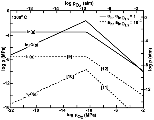
Partial pressures of In(g) and In2O(g) as function of oxygen partial pressure at 1300°C: bracketed numbers refer to reactions in text
In practice the indium and InO1·5 activities during the smelting of WEEE in a black copper operation will be small, so the partial pressure lines are also given for both activities of 0·0001 for illustration. It can be seen that for unit activities the indium vapour pressure is dominated by In2O(g) and is a maximum at an oxygen partial pressure of about 10−11 MPa (10−10 atm) i.e. under mildly reducing conditions. At low activity of indium and InO1·5 the total indium vapour pressure is dominated by In(g) and is constant at oxygen partial pressures below about 10−11 MPa (10−10 atm) and decreases rapidly under more oxidising conditions. This supports the observation of negligible indium losses during the present set of experiments, which were conducted at the higher oxygen partial pressure of 10−8 MPa (10−7 atm). The conclusion that indium is best volatilised under reducing conditions is supported by the experience at Teck Cominco Trail smelter where indium is fumed during lead slag fuming (Alfantazi and Moskalyk, 2003). Similarly, at Korea Zinc indium volatilises under reducing conditions during the smelting of zinc residue in TSL reactors (Outotec Oyj, 2012).
The first stage of black copper smelting involves reduction, where the oxygen partial pressure is typically less than 10−11 MPa (10−10 atm). Under these conditions LIns/m is 0·1 or less so indium reports mostly to the copper, but also fumes as In(g). Indium is present in WEEE as InO1·5 so a higher activity coefficient of InO1·5 in slag will result in a decreased concentration of InO1·5 in slag i.e. a high CaO slag is indicated for maximum indium recovery to fume. This benefit is likely to be offset by the resulting increased slag volume, and the associated economic penalties. Lime handling facilities will be required, and there will be an increase in the fuel demand.
It is interesting to reflect that in a blast furnace, where temperature decreases as the gases pass up the shaft, the fumed indium would be expected to reoxidise onto the charge and result both in an inefficient recirculating load of indium in the shaft and minimal indium vapour in the exit gas. Umicore use a blast furnace for reduction of slag from their TSL oxidising stage, and they reportedly recover indium from lead bullion during pyrometallurgical refining and not from blast furnace fume (Hagelüken, 2005). In a TSL reactor there is a large gas volume passing through the bath and no cool furnace top, so indium recovery to fume is expected to dominate. This is supported by the operations at Korea Zinc where, as noted above, indium is recovered from TSL fume (Outotec Oyj, 2012). Operating at as high a temperature as possible, within the constraints of fuel cost and refractory wear, will also increase the proportion of indium volatilised to fume. Recovery of indium from fume is preferred because it will be concentrated in a relatively small mass of material, from which it can be leached.
The second stage of black copper smelting often involves oxidation of the molten copper to remove impurities as oxides, which report to the slag or are volatilised. During this stage indium is best retained in the copper because it will then report to the anode slimes, from which it can be recovered by hydrometallurgical processing during the subsequent electrorefining of copper (Polinares, 2012). The slag/metal indium distribution ratio is always greater than unity under oxidising conditions but is minimised for a slag with a high CaO content, so such slags will maximise the proportion of indium reporting to the copper. Again, however, the potential benefits associated with the high CaO slag are unlikely to be realised for the same reasons as given above.
Conclusion
The development of efficient reprocessing methods for certain fractions of WEEE requires that information be available on the behaviour of valuable elements in WEEE during smelting.
In this work the distribution ratio of indium between FeOx–CaO–SiO2 slags and copper was examined at an oxygen partial pressure of 10−8 MPa (10−7 atm) and at 1300°C. The indium distribution ratio was strongly dependant on the CaO content, decreasing as the CaO content increased, but relatively unaffected by the Fe/SiO2 ratio of the slag over the range examined. It was inferred that indium was present in slag as InO1·5.
The activity coefficient of InO1·5 was calculated and presented as iso-activity coefficient curves on the copper-saturated FeOx–CaO–SiO2 phase diagram. The form of these curves i.e. their strong similarity to the iso-activity coefficient curves for CuO0·5, indicates that InO1·5 behaves as a neutral metal oxide in slag.
It was also concluded that indium recovery during WEEE processing in a black copper smelter takes place predominantly by volatilisation of In(g) during the reduction stage of black copper production. A slag containing a high CaO content will provide a lower indium loss to the slag, but is unlikely to be economically viable.
Footnotes
Acknowledgement
This work was performed as part of the doctoral thesis of one of the authors (AA). The authors wish to acknowledge the financial support provided by an Australian Government ARC Linkage Grant LP0776721 and thank the Head of the School of Civil, Environmental & Chemical Engineering at RMIT University for the provision of the facilities needed to carry out the work. They also thank Mr. Gordon Percival at Outotec Pty Ltd, Dandenong, Australia, for the chemical analysis of all samples.