
Abstract
The smelting of nickel laterite ores to ferronickel alloy is unique in extractive metallurgy. It treats feed that is very low grade with respect to the target metal and, as a result, produces much more waste slag than valuable metal product. The energy consumption per tonne of product is therefore high and requires sustained research and design development in an effort to improve the economics of laterite smelting. In this work, the main characteristics of nickel laterite smelting are reviewed, and then a simple and transparent computational thermodynamics model of the electric furnace smelting step is developed. This model predicts the nickel grade, nickel recovery and FeO content of the slag as functions of the iron recovery to ferronickel satisfactorily. It correctly predicts that the carbon and silicon contents in ferronickel increase sharply at high iron recoveries. However, in common with more sophisticated models, it incorrectly predicts the iron recovery at which this increase is observed in practice. It is concluded that the model provides an accessible and a satisfactorily accurate vehicle for understanding the relationships between process variables and process outcomes during nickel laterite smelting.
Introduction
Nickel is an important metal, with its use as an alloying element in steelmaking dominating all other uses. Most nickel is produced as the commercially pure metal, but approximately one-third of the world's new nickel is ferronickel. About 98% of all ferronickel produced is used for stainless steelmaking, and demand for stainless steel is forecast to continue to increase to meet the needs of the developing nations. World annual production of ferronickel is around 250 000 t, with the two largest producers being the Australian company BHP Billiton and the French company ERAMET, through its subsidiary Société Le Nickel (Cartman, 2010).
Most of the world's accessible nickel reserves, amounting to approximately 72% of the total, are oxidic ores called ‘laterite’ (Sudol, 2005). Nickel is also recovered from sulphide ore deposits, but the proportion produced from laterites has steadily increased until it reached 60% in 2013 (Cluzel, 2013). Laterites are the result of oxidation by chemical weathering, and supergene enrichment under tropical conditions, of mafic/ultramafic rocks. They vary greatly in depth, nickel grade, chemical composition and mineralogy (Dalvi et al., 2004). Being surface deposits, most laterites are cheaply mined using conventional earthmoving machinery. The upper layers are known as ‘limonite’ and are characterised by nickel contents from 0·8 to 1·5 wt-%, high iron contents and low magnesia and silica contents. The lower layers beside the bedrock are called ‘saprolite’ and have nickel contents from 1·8 to 3 wt-%, relatively low iron contents but high magnesia and silica contents.
The differing mineralogy of laterites requires different processing techniques, as a result of the form in which nickel is found in the two types of laterite. Nickel is loosely bound to goethite in limonitic ores but is incorporated into the lattice of magnesium silicate minerals in saprolitic ores (Bergman, 2003). As a result, limonites are suited for processing by hydrometallurgical methods whereas saprolites require treatment by pyrometallurgical methods (Cartman, 2010). Approximately 40% of all laterite mined is processed by pyrometallurgical methods (Dalvi et al., 2004), with about 90% of that involving the production of ferronickel alloys and the remainder being processed to nickel matte (Crundwell et al., 2011).
Crundwell et al. (2011) summarised the physicochemical principles and technology of smelting to ferronickel. Laterite is mined by open cut methods, minimally upgraded by screening to remove unaltered low-nickel bedrock, then crushed. It contains about 35 wt-% of free water so the ore is dried in a rotary kiln (RK), with the product still containing approximately 10–13 wt-% water, reported as ‘loss on ignition’ (LOI). Most of this water is chemically bound within such minerals as garnierite (Mg, Ni)3Si2O5(OH)4 and goethite FeO·OH so temperatures of 700 to 900°C are needed to remove it. The dried material, with some added coal, passes to large RKs where a natural gas, oil or coal flame heats the material. The coal volatiles and some of the fixed carbon partially reduce the ore. The remaining fixed carbon acts as the reductant in the following smelting step. The nature and reactivity of the added coal has a dramatic effect on kiln operations (Nelson et al., 2007). The use of unreactive coal, such as anthracite, results in very little kiln reduction and a red coloured product, while more reactive bituminous coals achieve the desired partial reduction and a black coloured kiln product.
There is disagreement in the literature regarding the extent of partial reduction achieved in kiln operations, probably as a result of local variations in operating practice. Crundwell et al. (2011) stated that most iron is reduced to FeO and that the extent of reduction of the oxides to metal is typically 25% for nickel, 20% for cobalt and 5% for iron. Daenuwy and Dalvi (1997) report that at the P.T. Inco smelter in Indonesia all of the Fe2O3 in the feed is reduced to Fe3O4 and FeO, with approximately 40% of iron present as Fe3+, 55% as Fe2+ and 5% as metallic iron. About 50% of nickel and 20% of cobalt are present in the metallic form, with the remainder being oxides. However, Solar (2013a) disagrees with their extents of reduction to the metallic form and believes that only 20% of nickel, 10% of cobalt and 1–2% of iron are reduced to the metals.
Hot calcine is fed to an electric furnace (EF) where virtually all of the remaining Fe3O4 is reduced to FeO and the NiO and CoO, together with part of the FeO, are reduced to molten ferronickel by the carbon in the calcine. The gangue oxides form slag. Finally, the molten ferronickel is refined to remove phosphorus and sulphur and, if necessary, to adjust the carbon and silicon contents in order to meet market specifications before casting or shotting to a 10–15 mm diameter product.
The flowsheet described above and shown as Fig. 1 is commonly referred to as the ‘RKEF process’ (Walker et al., 2009) because of its use of RK and EFs.
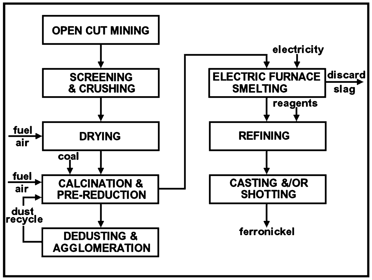
Generalised flowsheet of a laterite to ferronickel smelter
Smelting to ferronickel achieves a high recovery of nickel. However, energy consumption is high and this dictates that ore grade must be relatively high and electricity must be cheap if a ferronickel smelter is to be economic (Crundwell et al., 2011).
Thermodynamics of smelting
The oxide components of the feed to the EF are mainly NiO, FeO, SiO2 and MgO and the reductant is carbon. The Ellingham Diagram, given in Fig. 2, shows that at 1500–1600°C under standard state conditions, there is a thermodynamic driving force for the reduction of NiO and FeO by carbon, but that SiO2 and MgO are too stable to be significantly reduced. It is also apparent that preferential reduction of NiO should be possible.
However, NiO is not present in the furnace at unit activity but is dissolved in slag at low activity. The activity of NiO in molten calcine is estimated to be about 0·01 while in the tapped slag it will be 0·001, based on 90% recovery of nickel. The activity of nickel in molten ferronickel ranges from 0·2 to 0·4, i.e. not far from unity, so the oxygen potential of the reaction


The lines representing the equilibrium oxygen potential of the Ni/O2(g)/NiO reaction at NiO activities from 0·1 to 0·001 are also shown in Fig. 2. Activity corrections are not made to the line representing the Fe/O2/FeO reaction, because the activity of FeO in slag and iron in ferronickel are not far enough from unity to affect the general conclusions. It is now apparent that the initial driving force for the reduction of NiO is a little more favourable than that for FeO, but that FeO reduction is favoured when nickel recovery is high. Nickel laterite cannot be smelted to nickel, but to a ferronickel alloy.
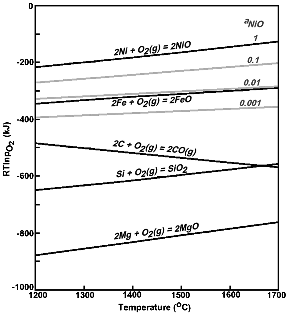
Ellingham diagram, with activity corrections, for reactions during nickel laterite smelting
The competing reductions of NiO and FeO can be represented by the reaction

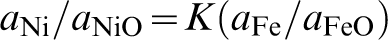
It is usual in industry to express the activity ratio of the nickel species as a ‘partition coefficient’ (Solar et al., 2008)


It follows that the recovery of nickel to the alloy will increase as the iron content of the alloy increases and therefore the FeO content of the slag decreases, i.e. as the nickel grade of the alloy decreases. The value of PCNi typically varies from approximately 175 to 250 (Solar et al., 2008) so very high nickel recoveries might be expected. However, nickel recovery also depends on the masses of ferronickel and slag produced and the slag mass is always much greater than the ferronickel mass. Solar et al. (2008) reported that the mass ratio of slag/ferronickel ranges from approximately 10 to 30 so that typical nickel recoveries vary from 90 to 95%.
The standard oxygen potential required for SiO2 reduction is only a little lower than that for the C/O2(g)/CO(g) equilibrium. Silicon will also be present in ferronickel at very low activity so a little silica reduction to silicon is expected at the higher extents of reduction. Under abnormally strong reducing conditions, SiO(g), and even a little Mg(g), can form and condense as SiO2, and MgO, in the off-gas system (Nelson et al., 2007).
The amount of energy which must be supplied for reduction is indicated by the standard enthalpy changes for the two main reduction reactions at the processing temperature of approximately 1550°C


The thermodynamic data were taken from the database of the HSC v7·1 software (Outotec Research Oy, 2013). Both reactions are strongly endothermic so the required energy input will be large, being typically about 500 kWh/t of calcine (Warner et al., 2006).
Industry surveys
Bergman (2003) presented and described the flowsheets of several nickel smelters while Warner et al. (2006) compiled extensive operating data. This was added by Solar et al. (2008) and included nickel, cobalt and iron distribution ratios and furnace recoveries, as well as product mass ratios. Furnace recovery is distinct from overall smelter recovery, which includes losses in all unit operations and unaccounted losses. Table 1 contains some important parameters on seven selected smelters. Several ferronickel smelters have commenced operations since 2006, but their operational data are yet to be made public.
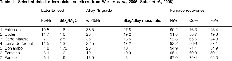
The quality of laterite feed is usually measured by the Fe/Ni and SiO2/MgO ratio and the quality of the ferronickel by its nickel grade, but Solar et al. (2008) showed that these three parameters are not useful for characterising smelter operations. The iron recovery to ferronickel is a much better indicator of the reducing conditions experienced in the EF. The first four smelters listed in Table 1 have relatively low iron reductions and so use mild reducing conditions, i.e. smaller proportions of carbon reductant in the calcine feed. However, the Fe/Ni ratio of their laterites varies widely from 7 to 29 and the ferronickels produced vary from 15 to 38·5 wt-%Ni. The final three smelters achieve much higher iron recoveries, but it is evident that they utilise only high-quality laterites and produce lower grades of ferronickel.
Solar et al. (2008) determined that low reducing conditions producing high-grade ferronickel are economically preferable. Although such operations have lower nickel recoveries than smelters using more strongly reducing conditions, they are characterised by lower power and reductant requirements, smaller off-gas volumes, higher furnace throughputs and lower refining costs.
It can also be seen in Table 1 that ferronickel smelting from laterites is characterised by the production of much more slag than alloy. This is in contrast to almost all other smelting processes where the slag mass is less than the metal or matte mass produced. The result is that the slag exerts a powerful influence on furnace operations.
Composition of the calcine
The composition of the partially reduced calcine feed to the EFs was not given by Warner et al. (2006), but can be calculated from the composition of the dried feed to the calcination/reduction kilns for various smelters. This information was reported and is listed in Table 2.
Composition of dried feed to calcination/reduction kilns for several smelters (from Warner et al., 2006)
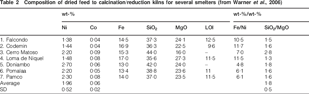
The nickel and cobalt contents of laterites do not vary much, but the Fe/Ni ratios vary considerably. The SiO2/MgO ratio averages 1·8, although it was unusually high for the Cerro Matoso laterite that was being smelted at the time of the survey. The water content, given as ‘LOI’, is typically 10–13 wt-%.
Electric furnace design
Hot calcine is smelted in EFs in which the heat is generated by the passage of large electric currents through the arc plasma and slag between suspended carbon electrodes. Some furnaces still operate in resistive mode, i.e. without an arc gap. The furnace is lined with high-quality MgO refractories and is fitted with embedded water-cooled copper elements in the sidewall. Calcine is charged through feed pipes in the roof. Such a furnace typically consumes up to 4000 t day−1 of hot calcine, produces up to 250 t day−1 of ferronickel and 3700 t day−1 of slag (Crundwell et al., 2011).
Electric furnaces are either circular in shape, with three electrodes positioned at the corners of an equilateral triangle, or rectangular, with six inline electrodes. The recently constructed Société du Nickel de Nouvelle-Calédonie et Corée Pty Ltd (SNNC) and Jusikhoesa Poseuko (POSCO) joint venture smelter in Korea has a state-of-the-art circular furnace which is 22·2 m diameter by 7·7 m tall, has 1·8 m diameter electrodes with a power rating of 94 MW and is equipped with 27 feed pipes (Rodd et al., 2010). Rectangular furnaces are less common, although may become more popular as furnace power levels increase. Having six electrodes, they generate half as much reaction gas per electrode as the circular furnaces and this improves feed behaviour around the electrodes. A typical rectangular furnace, at the Falcondo smelter, is 24·3 m long, 8·8 m wide and 7·3 m high with 1·4 m diameter electrodes and a power rating of 56 MW (Warner et al., 2006).
Earlier electric arc furnaces operated in the ‘immersed electrode’ mode, i.e. the electrodes dipped into the slag and all heat was generated by Joule heating of the slag. Heat was transferred from the hot slag to the overlying calcine (Crundwell et al., 2011). Higher throughputs require higher power input. Increased power levels have the benefits of a decreasing proportion of the input energy being lost and a significantly lower capital cost per tonne of calcine smelted (Walker et al., 2010); however, higher power levels with ‘immersed electrode’ smelting result in operating difficulties. Increased power dissipation in the slag raises the slag bath temperature, resulting in higher sidewall heat flux and refractory wear, higher electrode consumption because of the higher currents and the need for physically larger and more costly transformers, busbars and electrodes (Voermann et al., 2004).
The problems with immersed electrode smelting were overcome during the 1960s and 1970s by the development of the ‘shielded arc’ method. In this mode, the electrodes sit above the slag and current passes by arcing through a plasma gap, then through the slag and finally through another plasma gap to the matching electrode (Janzen et al., 2004). This mode of operation is shown in Fig. 3.
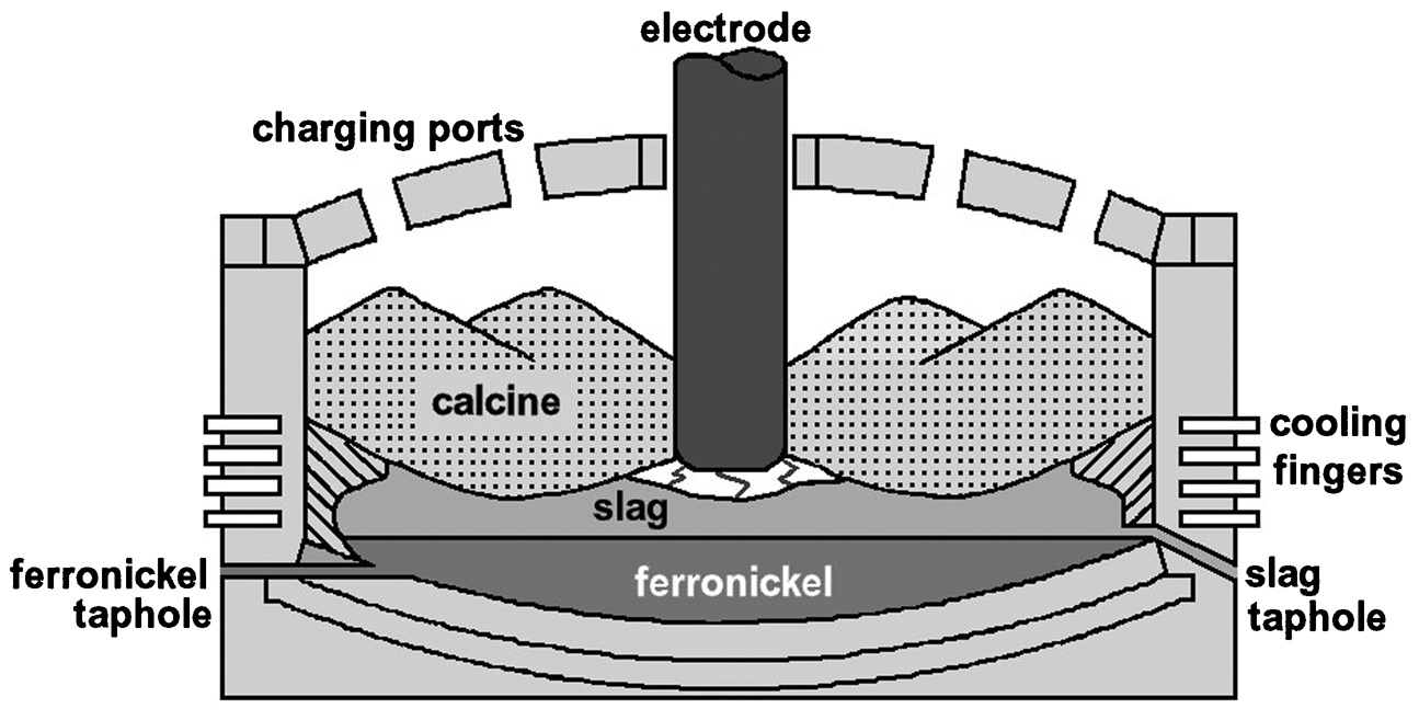
Cross-section of an electric arc furnace operating in ‘shielded arc’ mode
The total power to the furnace, Pt, can be expressed as the sum of the power dissipated in the arcs, Pa, and that dissipated in the slag, Pb
Voermann et al. (2004) showed that for the simplest case of a single-phase operation and a power factor of 1

Power density, i.e. the power per square metre of hearth area, is an important factor in furnace design, because the larger the power density, the smaller the heat losses relative to the production rate (Rodd et al., 2010). However, sidewall heat flux is increased so very efficient water-cooled copper elements in the furnace sidewalls are required (Voermann et al., 2004). The SNNC furnace has a high power density of 270 kW m−2 (Rodd et al., 2010), but Walker et al. (2009) believed that a 120-MW furnace with a power density as high as 375 kW m−2 could be successfully built and operated.
The reduction of calcine to ferronickel results in the production of a large volume of waste gas, largely carbon monoxide, e.g. the SNNC furnace produces up to 85 000 m3 h−2. Calcine must be charged close to the electrodes so that it can receive heat from the arcs, so this gas flow is also concentrated around the electrodes (Rodd et al., 2010). This can result in fluidisation of the calcine and interrupted feeding into the arc zone, so calcine must be carefully sized to maintain adequate gas permeability. If the calcine ‘shield’ around the electrodes is not maintained then lower power efficiency and possible roof and feed pipe damage results (Nelson et al., 2007).
A ferronickel arc furnace has several control requirements. It must smelt calcine at the required rate to produce the target nickel grade of alloy with the required slag and metal temperatures to allow both the maintenance of a slag freeze layer on the refractories and easy tapping of the slag. This requires an appropriate ratio of arc power (Pa) to bath power (Pb), which is achieved by manipulation of the arc length and control of the slag depth (Crundwell et al., 2011). The hot calcine feedrate must also be carefully controlled. If too low then the arcs will be uncovered and the furnace roof will overheat, while if too high then the furnace could be filled to the roof and this severely impedes the flow of waste gas (Janzen et al., 2004).
Furnace products: Ferronickel
The target nickel grade of the ferronickel produced is largely a function of perceived customer preferences (Solar et al., 2008) and can range from 17 to almost 40 wt-%Ni. Nickel grade is not determined by the quality of the laterite, as expressed by the Fe/Ni ratio. Cerro Matoso laterite had an Fe/Ni ratio of 7 and produced a 35 wt-%Ni alloy, while Pamco smelts laterite with a similar ratio of 6·1 but to an 18·5 wt-%alloy.
The composition of ferronickel alloys produced by several smelters is given in Table 3. Ferronickels from low iron reduction smelters (1–4) are very close to binary Fe–Ni alloys, whereas those from high iron reduction smelters (5–7) contain significant amounts of carbon, silicon and chromium, whose concentrations are very similar. The high silicon content makes these alloys unsuited for direct use in stainless steelmaking, where the silicon specification of the steels is low, so they need to be refined to remove most of the silicon before sale (Crundwell et al., 2011). Refining also removes most of the carbon and chromium.
Ferronickel compositions and tapping temperatures (from Warner et al., 2006)
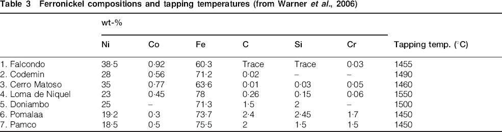
The liquidus temperature of ferronickel is strongly affected by its composition and can be estimated from the Fe–Ni–C phase diagram shown in Fig. 4. Alloys from low iron reduction smelters (1–4) have liquidus temperatures in the range 1450–1460°C but alloys from high iron reduction smelters (5–7) have liquidus temperatures from 1350°C to as low as 1250°C.
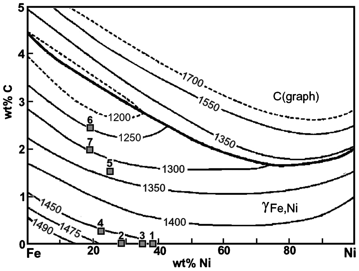
Liquid temperatures of Fe–Ni–C alloys (Lebrun and Perrot, 2008), together with the composition of ferronickel from selected smelters. 1: Falcondo; 2: Codemin; 3: Cerro Matoso; 4: Loma de Niquel; 5: Doniambo; 6: Pomalaa; 7: Pamco
The required alloy temperature for ease of tapping must be at least 25°C above the metal liquidus, i.e. the metal superheat (ΔTsuper) must be about 25°C (Voermann et al., 2004). However, the minimum furnace operating temperature is set by the slag, because it typically has a liquidus temperature above 1550°C. It follows that the molten ferronickel is highly superheated. This has a significant impact on furnace design, because the heat flux to the sidewall in contact with the molten alloy is proportional to ΔTsuper4/3, so that there is a need for very strong cooling of the sidewall in contact with the molten alloy (Voermann et al., 2004). For low iron reduction smelters, where the alloy liquidus temperature is high, the heat flux is approximately 1200 kW m−2, but for high iron reduction smelters, where the alloy liquidus temperature is low, the heat flux is typically 5000 kW m−2. High alloy superheat does have the benefit, however, of limiting the formation of solidified layers in the ladle when the alloy is transferred to refining and minimising additional heating required during refining (Nelson et al., 2007).
Finally, the target nickel grade affects the metallurgical performance of the smelter. Producing high-grade ferronickels involves less reduction of FeO to iron and so leads to increased throughput, lower overall energy consumption and lower reductant consumption. However, these benefits come at the expense of a decreased nickel recovery in the EF (Crundwell et al., 2011). Falcondo is a high-grade ferronickel producer with a calcine throughput of 0·84 t h−1 m−2 at an energy consumption of 379 kWh/t and a furnace nickel recovery of 90%, while Pomalaa is a low-grade ferronickel producer with a throughput of 0·19 t h−1 m−2, a power consumption of 600 kWh/t and a furnace nickel recovery of 95% (Warner et al., 2006).
Furnace products: Slag
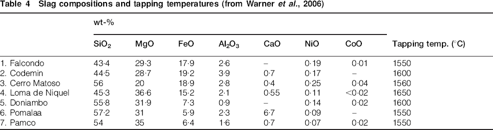
The major components of laterite smelting slags are FeO, SiO2 and MgO, while there are also small amounts of Al2O3 and CaO. A ferronickel furnace is mainly a producer of slag, which comprises over 90% of the furnace output. Modification of the slag composition through the addition of fluxes would require large amounts of flux and so is rarely economic (Utigard, 1994). It follows that the properties of the slag are determined by the SiO2/MgO ratio of the laterite ore and the concentration of unreduced FeO, which depends on the Fe/Ni ratio of the laterite and the extent of reduction achieved in the furnace. The slag compositions and tapping temperatures for the selected smelters (Warner et al., 2006) are summarised in Table 4.
Slag compositions and tapping temperatures (from Warner et al., 2006)
The slag composition can be projected onto a convenient form of the FeO–SiO2–MgO ternary phase diagram to allow estimates to be made of the liquidus temperature of the slag. Figure 5 shows that the FeO–SiO2–MgO system is characterised by a low liquidus temperature ‘valley’. On the low silica side, the liquidus temperatures increase steeply with decrease in the SiO2/MgO ratio and are almost independent of the FeO content of the slag. On the high silica side, liquidus temperatures are strongly dependent on the FeO content of the slag.
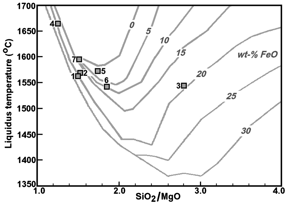
Liquidus temperatures of SiO2–MgO–FeO slags in equilibrium with iron (from Levin et al., 1964). The normalised compositions for several smelters are shown. 1: Falcondo; 2: Codemin; 3: Cerro Matoso; 4: Loma de Niquel; 5: Doniambo; 6: Pomalaa; 7: Pamco
It can be seen that most smelters have slags with liquidus temperatures in the range 1550–1600°C and lie close to the bottom of the ‘valley’ on the phase diagram. Loma de Niquel has an unusually high liquidus temperature because of the low SiO2/MgO ratio of its laterite and this could not be significantly reduced by decreasing the extent of reduction in the furnace, i.e. increasing the FeO content. Cerro Matoso slag had a relatively low liquidus temperature, which would increase rapidly if more FeO was reduced from the slag, i.e. Cerro Matoso could not have produced low-grade ferronickel alloy without substantially increasing the liquidus temperature of its slag.
The presence of a small amount of Al2O3 in all slags affects the liquidus temperature predictions. Jak and Hayes (2010) showed that the presence of 3 wt-%Al2O3 in slag lowered the liquidus temperature by up to 50°C. These decreased liquidus temperatures increase the slag superheat, i.e. the difference between the furnace operating temperature and the slag liquidus temperature. Increased slag superheat significantly increases the difficulty of containing the slag within the furnace.
Slag superheat also has a strong effect on furnace design. Voermann et al. (2004) showed that the rate of heat transfer to the sidewalls is directly proportional to the slag superheat and the power density, i.e. the power dissipated in the bath (Pb) per unit area of bath cross-sectional area. It is very important that a frozen layer of slag be maintained on the sidewalls to protect the refractories so furnaces with high heat fluxes require very effective cooling, such as that provided by Hatch waffle coolers (Hatch and Wasmund, 1974).
Slag viscosity is a very important parameter. Slag tapping temperature must be at least 50°C above the slag liquidus to ensure sufficient slag fluidity for good metal/slag separation and slag tapping (Voermann et al., 2004). Viscosity also affects the rate of slag attack on the refractories, as does the SiO2/MgO ratio. The higher the SiO2/MgO ratio, the more severe the attack on MgO refractories (Dalvi et al., 2004). The propensity for a slag to foam as the large volume of waste gases vents through the slag is also a function of slag viscosity. Finally, the ferronickel droplet residence time in the slag increases with slag viscosity and this leads to higher mechanical losses of ferronickel to the slag. The viscosity data of Jak and Hayes (2010) are shown in Fig. 6, where it can be seen that viscosity increases with decreasing FeO content, especially for slags with high SiO2/MgO ratio. Droplet residence time is also a function of the interfacial tension of the slag and this decreases as the FeO content of the slag increases, so mechanical alloy losses to slag will also decrease with increasing FeO content (Broadbent and Machingawuta, 1993).
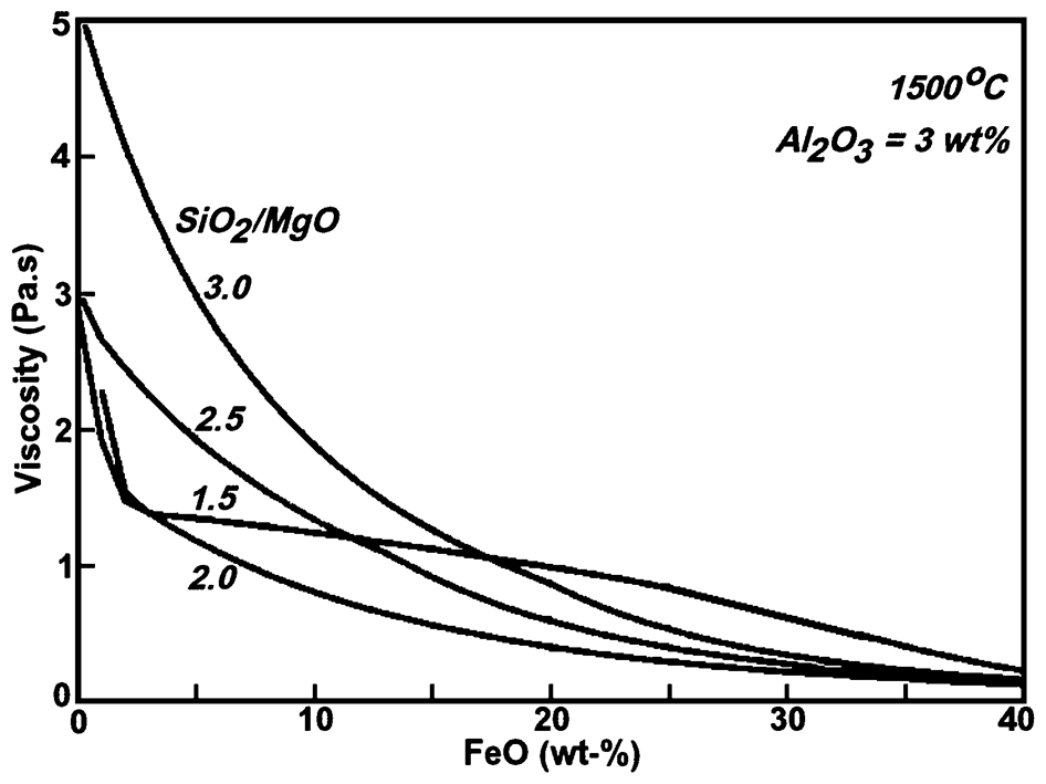
Viscosity of slags containing 3 wt-%Al2O3 and various SiO2/MgO ratios at 1500°C (Jak and Hayes, 2010)
Methodology
HSC simulation
HSC Chemistry for Windows v.7·1 software package (Outotec Research Oy, 2013) is a convenient way to determine the equilibrium state of a multicomponent multiphase system and has been successfully used to examine metallurgical processes such as ferromanganese smelting (Vanderstaay et al., 2004), lead concentrates smelting (Yamaguchi et al., 2005), the argon oxygen decarburisation (AOD) process for stainless steelmaking (Swinbourne and Kho, 2012) and copper flash converting (Swinbourne and Kho, 2012). The software takes the specification of all likely phases in the system as inputs: the species which are, or likely to be created, in each phase; the activity coefficients of all species in each phase; the masses of all input species and the temperature and pressure of the system. A Gibbs free energy minimisation routine is employed to output the quantities of all species in all phases at equilibrium. As such, it provides valuable information on the effects of process variables on the amounts and compositions of molten phases as a function of temperature or the amount of one or more of the inputs.
Input amounts of species
Thermodynamic modelling of a process ideally requires that there are reliable industrial data available for comparison with the predicted outcomes. It was found that the data for smelters listed in Table 1 contained many inconsistencies as indicated by element mass balances that failed to close, which indicates inaccurate data, and that no information was provided on the composition of the partially reduced calcine entering the EFs. As a result, representative feeds were determined based on the data in Table 2.
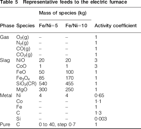
It was assumed that calcine feeds contained only Ni, NiO, CoO, FeO, Fe3O4, SiO2 and MgO, because the Al2O3 content is too small to be significant, and the addition of burnt lime as a flux is uncommon. Typical calcine feeds were therefore considered to contain 2 wt-% total Ni, have Fe/Ni (wt-%/wt-%) ratios of 5 and 10 and have a SiO2/MgO (wt-%/wt-%) ratio of 1·8. A small amount of CoO was included so that the behaviour of cobalt could be examined. Nickel metallisation was assumed as 20% while that of cobalt was ignored because the mass of CoO is very small and the carbon requirement in the EF would not be significantly affected by neglecting it. Iron oxides were assumed to comprise 40%Fe3+ and 60%Fe2+ based on the data of Daenuwy and Dalvi (1997). Rather than creating a separate phase for the calcine feed, the oxides were allocated to an initial slag phase and the metals were allocated to an initial metal phase. The assumed phases, species in each phase, initial masses of each species (rounded to integer values) and their activity coefficients are given in Table 5. The activity coefficient values are justified below.
Representative feeds to the electric furnace
Activity coefficient values
The gas phase can be considered as an ideal solution at high temperatures so that the activity coefficients of all gas species were considered as unity.
Selection of appropriate values for the activity coefficients of all species in the molten phases is the most difficult aspect of modelling. HSC 7·1 does not contain solution databases, so activity coefficients must be found from the literature. Swinbourne (2011) has argued that this is a distinct advantage of the HSC package when used in the educational context, because it requires users to find and critically evaluate appropriate data themselves. Activity coefficients are a function of the composition of the phase concerned, but HSC only provides for constant values of the activity coefficient so representative values for the composition ranges considered likely must be selected. This limitation does not detract from the value of the modelling for predicting trends in smelter outcomes as a function of process variables. It is also not essential to have precise values of activity coefficients because small variations in value have little impact on the predicted process outcomes.
Ferronickel
The activities of iron and nickel in ferronickel alloys were determined by Conard et al. (1978) at 1600°C using mass spectrometry, and they also reviewed the earlier work of Zellars et al. (1959), Speiser et al. (1959) and Belton and Fruehan (1967). Their results are shown in Fig. 7. It can be seen that the activity coefficient of iron is close to unity for alloys of relevance to laterite smelting. There is greater disagreement regarding the activity coefficient of nickel, but a value of 0·65 is a reasonable estimate and would not be expected to be significantly different at 1550°C.
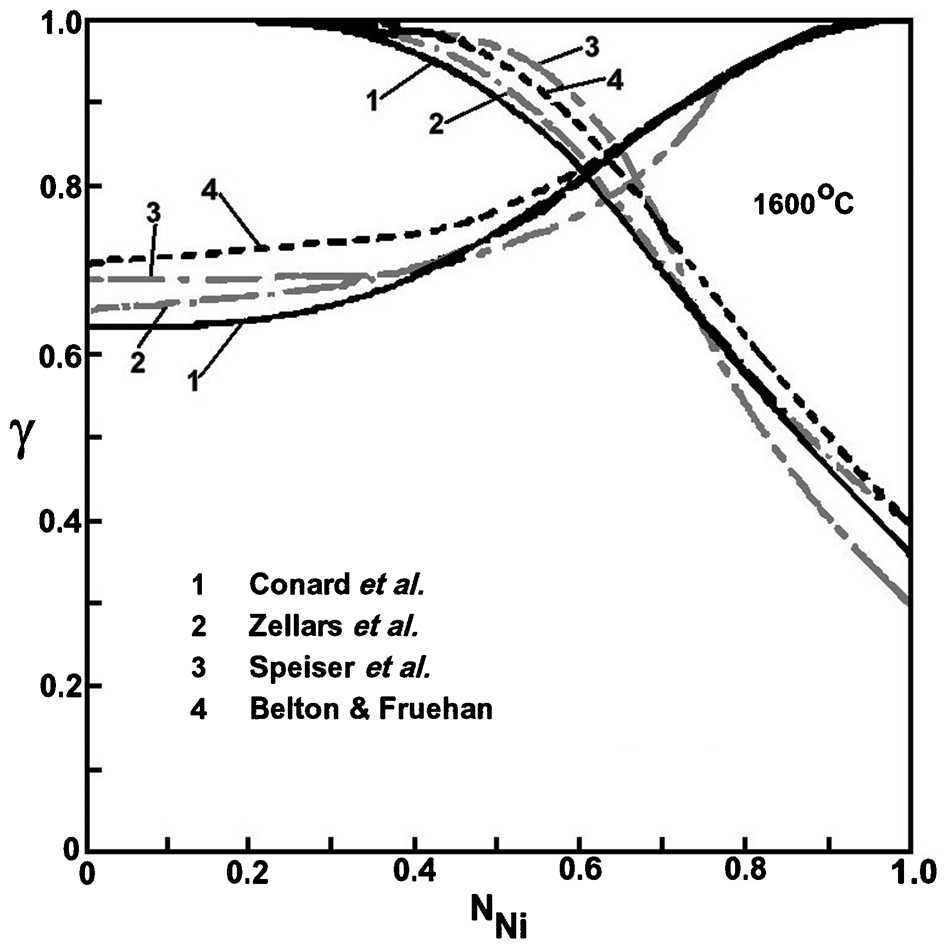
The activity coefficient of iron and nickel in ferronickel alloys at 1600°C (Conard et al., 1978)
Belton and Fruehan (1967) showed that the limiting activity coefficient of cobalt in iron–cobalt alloys at 1590°C is very close to 1·1.
The activity coefficients of carbon and silicon in molten ferronickel were estimated using the dilute solution model described by Sigworth and Elliott (1974), using the tabulation of Lupis (1983) for the interaction coefficients. The activity coefficients are given by the following equation
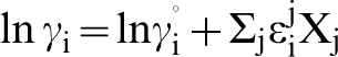
 is the Raoultian activity coefficient at infinite dilution,
 is the binary first-order interaction coefficient between species i and j, and Xj is the mole fraction of species j. Table 4 shows that alloys containing high nickel contents have very little carbon, hence only the calculated activity coefficients of carbon (graphite) in molten iron and 20 wt-%Ni–Fe are shown in Fig. 8. Elliott et al.'s (1963) data for Fe–C alloys are also shown and are in good agreement with the calculated values. It can be seen that the activity coefficient of carbon increases as the nickel content of the alloy and the carbon content increases. A representative activity coefficient of carbon was assumed to be 1·3. It was also found that this value was satisfactory over the range 1450–1650°C.
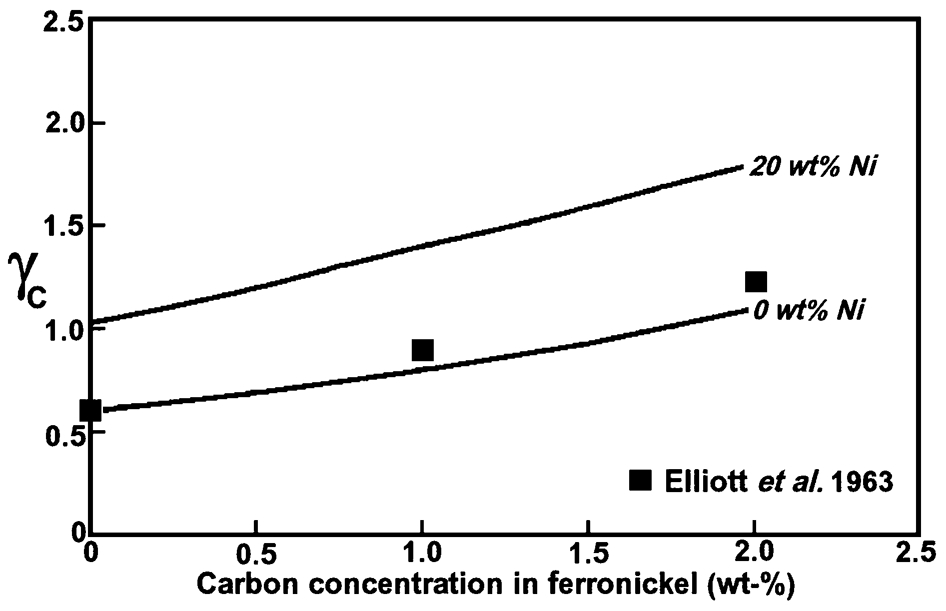
Activity coefficient of carbon in ferronickel alloys as a function of nickel and carbon contents at 1550°C
The Sigworth–Elliott model (Sigworth and Elliott, 1974) was also used to calculate a value for the activity coefficient of 0·003 for silicon. Vogel and Palme (2004) determined the activity coefficient of silicon in carbon-free iron–nickel alloys at 1300 to1400°C and their data indicate, by extrapolation, that a value of 0·003 is reasonable.
Slag
Kojima et al. (1969) determined the activity of FeO in FeO–MgO–SiO2 slags at 1600°C. These data were used to calculate the activity coefficient of FeO over the liquid field and this is shown in Fig. 9. The value of the activity coefficient is not very sensitive to composition at low FeO concentrations, varying from 0·8 at the silica-saturation boundary to about 1·4 at the olivine-saturation boundary. A value of unity was considered to be a satisfactory representation for typical ferronickel slags.
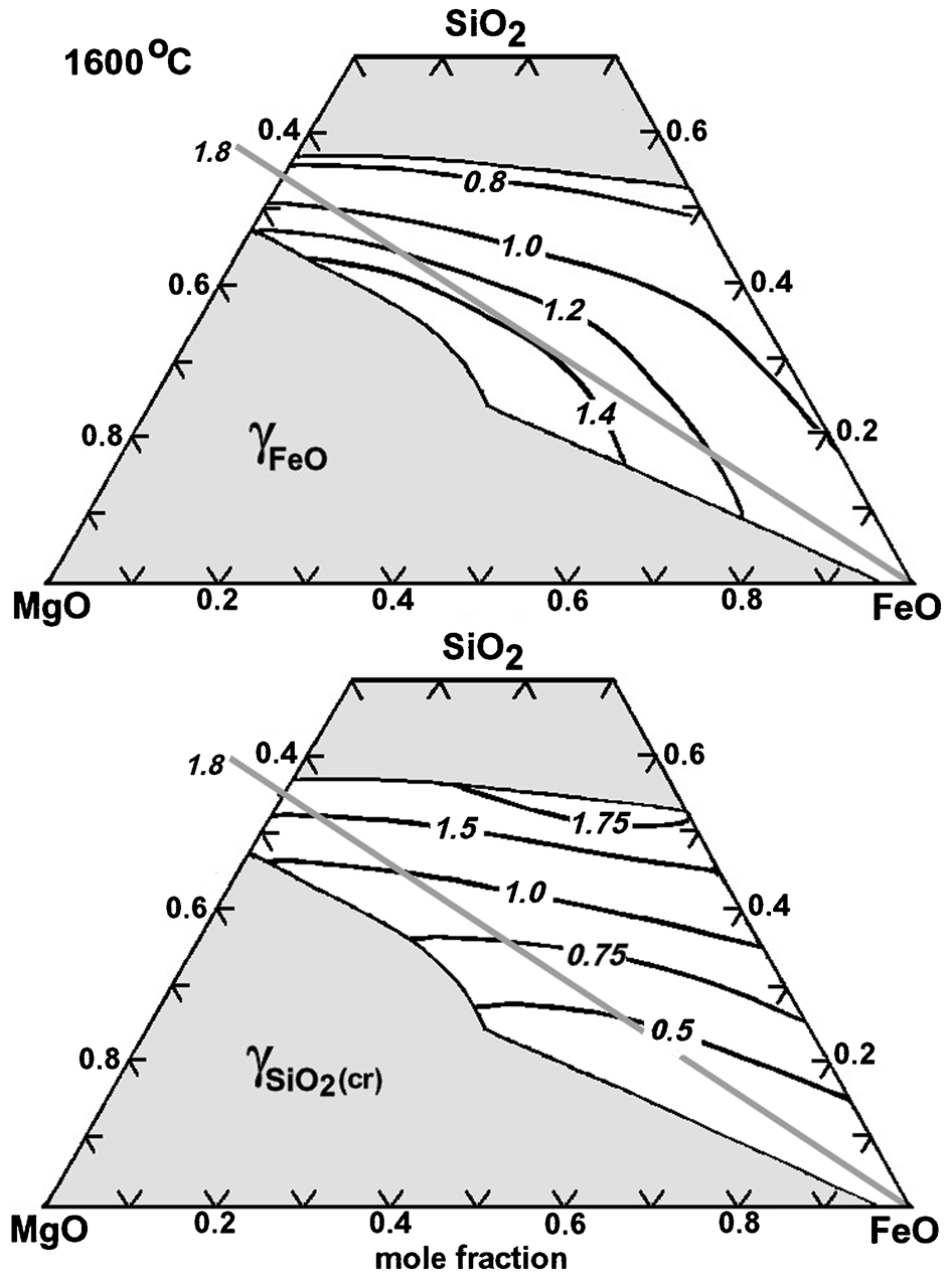
Activity coefficients of FeO(l) and SiO2(cr) in the SiO2–MgO–FeO system at 1600°C
The activity coefficient of Fe3O4 in slag was considered as unity because, under the reducing conditions in the EF, it would not be present in the final slag. As a result, the activity coefficient assigned to it is not important.
Experimental activity data for SiO2 in FeO–SiO2–MgO slags could not be found, so FactSage 6·3·1 software (Bale et al., 2002) using the FToxid solution database for liquid slag and FSstel solution database for the liquid iron were used to calculate values. The standard state was pure solid cristobalite. The results are also shown in Fig. 9, where it can be seen that values vary from about 1·75 near the silica-saturation boundary to between 0·75 and 1 along the olivine-saturation boundary. A value of unity was also considered to be a satisfactory representation of the activity coefficient of SiO2(cr) for typical ferronickel slags.
The activity coefficient of NiO(s) in FeO x –MgO–SiO2 slags at 1500°C was determined by Henao et al. (2001). Their results are scattered between 2 and 7, but an average value for the activity coefficient of NiO(s) of 3·5, independent of the FeO x content of the slag, is reasonable. This is close to the value of 3 reported by Pagador et al. (1997). In ferronickel smelting, the temperature of the slag is 1550–1600°C, and an increased temperature would shift the value of all activity coefficients towards unity, so the activity coefficient of NiO used in this work was assumed as 3.
Henao et al. (2001) reported data for CoO in FeO x –SiO2–MgO slags containing approximately 10 wt-%Al2O3. The activity coefficient of CoO(s) in such slags was very similar to that reported for NiO(s), although again the scatter is considerable, so the activity coefficient of CoO(s) in Al2O3-free slags was assumed to be the same as that of NiO(s).
Temperature
The electric arc furnace is not an isothermal reactor. The temperature in the arc cavity is high but the residence time of alloy/slag droplets in that region is short. Both phases are in contact for the maximum time at the alloy/slag interface so the temperature of this region should be used for equilibrium calculations. The average tapping temperature of ferronickel for the selected smelters given in Table 3 is 1480°C, while that of the slag is 1580°C. As a result, the appropriate temperature for modelling will be considered as 1550°C.
Results and Discussion
The nickel grade and recovery of nickel to the alloy are a function of the amount of carbon present in calcine feed to the EF (Crundwell et al., 2011), so the amount of carbon in calcine will be used as the independent variable in the modelling studies. The recoveries of nickel, cobalt and iron are shown in Fig. 10. The curves for nickel and cobalt are identical for both calcines, but the iron recovery is strongly affected by the Fe/Ni ratio because of the different amounts of iron in them.
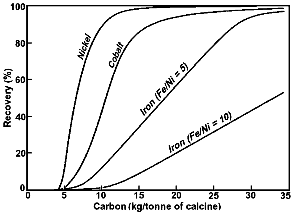
Recoveries of nickel, cobalt and iron as a function of carbon in calcine feed (Fe/Ni = 10)
There is no metallic phase present at very low carbon additions, although there was metallic nickel in the feed to the EF as a result of pre-reduction in the kiln. Nickel initially reacts with the small quantity of Fe3O4 present to produce FeO and NiO, the reaction being driven by the low activity of NiO in slag. Carbon then preferentially reduces the remaining Fe3O4 to FeO. The recovery of nickel is close to 100% at 20 kg/t of carbon, with the cobalt recovery being about 90%. Iron recovery increases almost linearly with the quantity of carbon in calcine.
The composition of the ferronickel is shown in Fig. 11. High-grade alloys containing 35–40 wt-%Ni require approximately 15–20 kg of carbon per tonne of calcine, i.e. 1·5–2·0 wt-% carbon in calcine. Low-grade alloys containing 17–20 wt-%Ni require approximately 25–30 kg/t of calcine, i.e. about 2·5–3·0 wt-% carbon in calcine. These carbon contents are in good agreement with those used in practice (Crundwell et al., 2011).
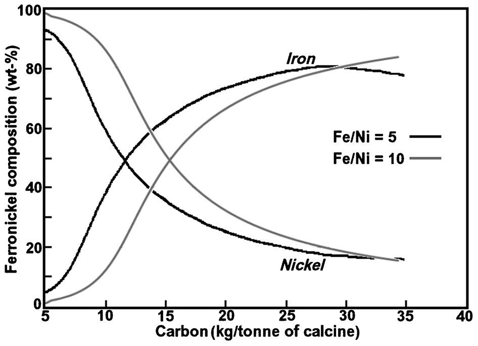
Composition of ferronickel as a function of carbon in calcine feed
While the Fe/Ni ratio of the calcine has a minimal effect on the concentrations of nickel and iron in ferronickel, it has a strong effect on the carbon and silicon contents. The carbon and silicon contents of ferronickel are shown in Fig. 12, together with the cobalt content, for the calcine having an Fe/Ni ratio of 5. The cobalt concentration quickly reaches a maximum and then decreases as more iron is reduced into the alloy. There is a steep increase in both silicon and carbon contents at high levels of carbon in calcine, which explains the small decrease in iron content of the alloy above 30 kg/t of carbon as shown in Fig. 11. Results for the calcine having an Fe/Ni ratio of 10 are shown in Fig. 13. The silicon content of the ferronickel alloy is negligible for all carbon additions. The carbon content increases steadily with increasing carbon in the calcine, but is about 30 times less at high carbon additions than that observed when the calcine had an Fe/Ni ratio of 5.
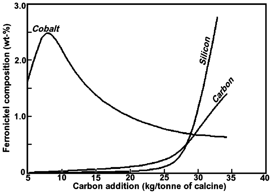
Minor components of ferronickel as a function of carbon in calcine having Fe/Ni = 5
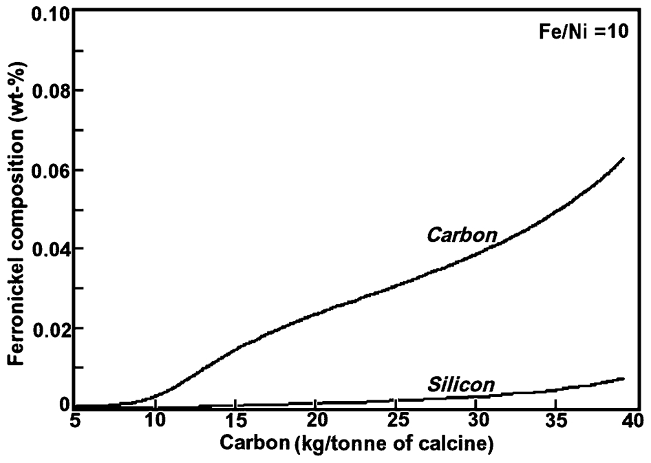
Minor components of ferronickel as a function of carbon in calcine feed (Fe/Ni = 10)
These qualitative trends in composition are confirmed by the data in Tables 1 and 3. Smelters having calcines with Fe/Ni ratios from 5 to 7 produce low carbon ferronickel when the nickel grade is high, as at Cerro Matoso, but high carbon ferronickel when the nickel grade is low, as at Pomalaa. When the Fe/Ni ratio in calcine is above 10, the alloy is almost carbon-free for high-grade alloys, as seen for Falcondo, and contains only a little carbon when the nickel grade is low, e.g. Codemin.
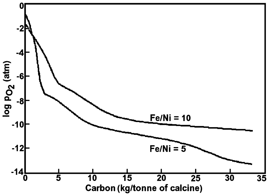
The smelting of calcines with low Fe/Ni ratios results in significant carbon and silicon contents in the ferronickel because when low-grade alloys are produced, most of the iron is in the alloy. As a result, the FeO content of the slag is much lower than when calcines with high Fe/Ni ratios are smelted, as can be seen in Table 4. The partial pressure of oxygen in the system is a function of the concentration of the most unstable oxide in slag, i.e. FeO. The Fe/FeO/O2(g) equilibrium is given by the following reaction

Rearranging the equilibrium constant expression and taking logarithms gives

Ferronickel alloys contain 60 to 80 wt-% iron so that the activity of iron is not far from unity, and hence the logarithm of the iron activity is close to zero. Assuming that the activity of FeO is proportional to its concentration, a decrease in the FeO concentration by a factor of 10 results in a decrease in the partial pressure of oxygen by a factor of 100 times. This decrease in partial pressure causes some SiO2 to be reduced to silicon and carbon dissolving into the ferronickel. These trends in partial pressure of oxygen as a function of the carbon in calcine are shown in Fig. 14.
Partial pressure of oxygen as a function of the carbon in calcine, at 1550°C
Finally, the effect of temperature on the silicon and carbon contents of ferronickel was examined for a calcine with an Fe/Ni ratio of 5 and 30 kg/t of carbon in calcine. The results are shown in Fig. 15. The carbon content decreases with increase in temperature, but the silicon content increases rapidly. This accounts for the process upset known as ‘silicon reversion’, which only occurs under very reducing conditions (Walker et al., 2010). Ferronickel droplets formed in the arc craters are hotter than the average slag temperature and have silicon contents well above the equilibrium value appropriate for alloys at that average temperature. As these droplets pass through the slag layer, FeO in slag reoxidises the silicon in the alloy droplets by a reaction that is very exothermic
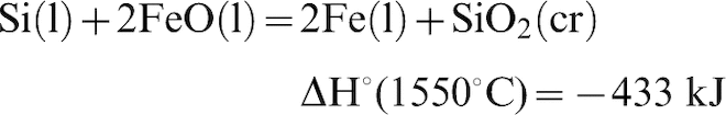
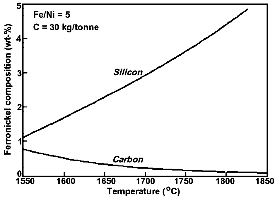
Carbon and silicon contents of ferronickel as a function of temperature for Fe/Ni = 5 laterite and 30 kg of carbon per tonne of calcine feed
The now superheated alloy droplets join the bulk of the ferronickel and raise the temperature of the metal bath. This results in increased heat transfer to the refractories and penetration of the refractories by the alloy, which severely compromises the refractories. Furnace power has to be reduced, which decreases throughput (Walker et al., 2010).
Comparisons with plant data
Comparison of the model predictions with industrial data is not possible on the basis of the amount of carbon in calcine, because this figure is rarely reported. Solar et al. (2008) used the iron recovery in the ferronickel as a measure of the extent of reduction, and this permits useful comparisons to be made. The relationship between nickel grade and iron recovery is shown in Fig. 16. The agreement between the model predictions and the industrial data, taken from Table 1, is seen to be excellent.
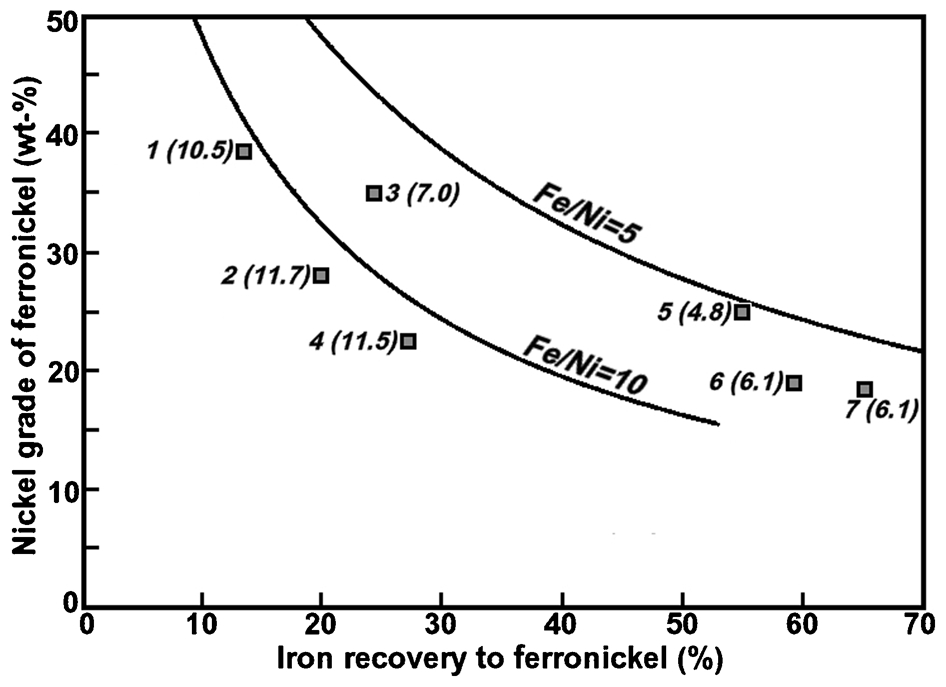
Comparison of the predicted nickel grade of ferronickel with industrial data, where the Fe/Ni ratio in the calcine is given in parentheses. 1: Falcondo; 2: Codemin; 3: Cerro Matoso; 4: Loma de Niquel; 5: Doniambo; 6: Pomalaa; 7: Pamco
The FeO content of the slag is a function of the iron recovery, but is also affected by the SiO2/MgO ratio in the calcine and the presence of other oxides that report to the slag, such as Al2O3 and CaO. A comparison of the model prediction of the FeO content of slag and industrial data is given in Fig. 17. The agreement is very good for the smelters operating with high recoveries of iron, but less satisfactory for those operating with low extents of iron reduction. The discrepancies do not necessarily suggest deficiencies in the model. Mass balances on the data provided by Warner et al. (2006) for the seven smelters considered in this work do not all close well, indicating errors in the data reported by the smelters in the questionnaire sent to them for completion. These errors can be due to sampling issues. Saprolite ores are very difficult to sample because there is a strong correlation between particle size and mineralogy, and therefore to composition. The fines are richer in nickel and iron, and poorer in MgO, than the coarse material. Plant samples are typically biased towards the fine sizes (Solar, 2013b).
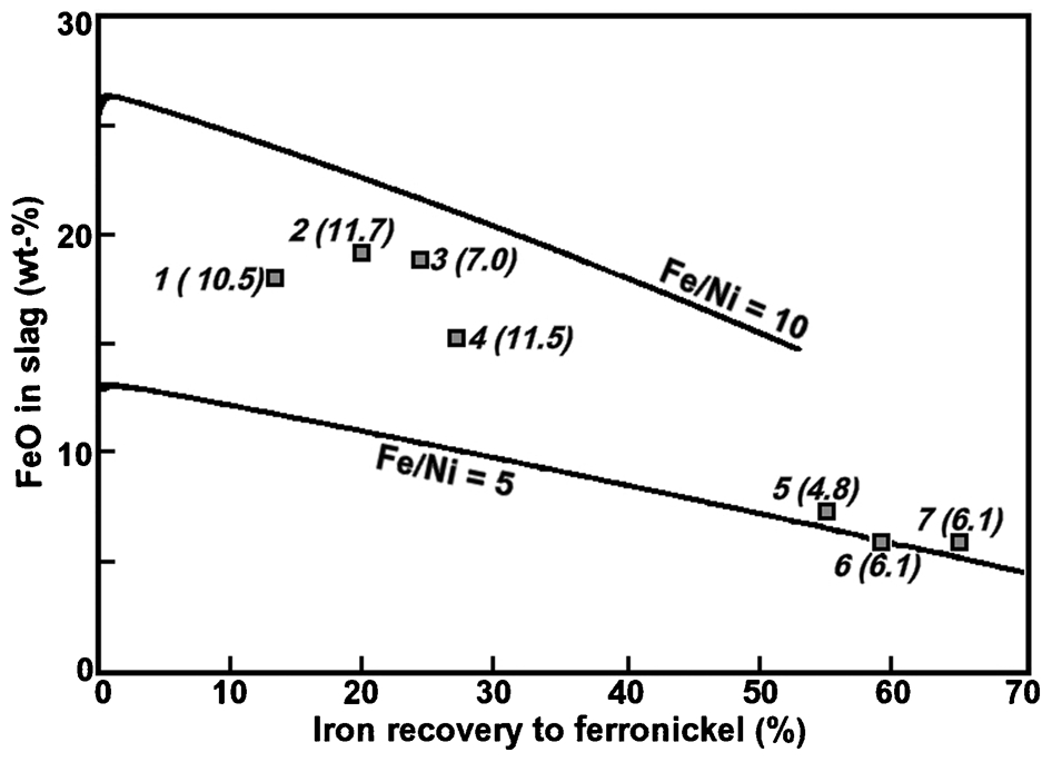
Comparison of the predicted FeO content of slag with industrial data, where the Fe/Ni ratio in the feed calcine is given in parentheses. 1: Falcondo; 2: Codemin; 3: Cerro Matoso; 4: Loma de Niquel; 5: Doniambo; 6: Pomalaa; 7: Pamco
The predicted carbon and silicon contents of ferronickels are compared to plant data in Figs. 18 and 19, where a logarithmic scale is used to expand the low concentration range. The carbon content for Falcondo ferronickel cannot be shown because it was given as ‘trace’ (Warner et al., 2006). Similarly, the silicon contents for Falcondo and Codemin ferronickel cannot be shown in Fig. 19 because they were given as ‘0’ (Warner et al., 2006). The data for the low iron reduction smelters are in acceptable agreement with the predictions, but that for the high iron recovery smelters are not. The modelling predicts that the high carbon and silicon contents reported in ferronickels from high iron recovery smelters should not be reached until iron recoveries of about 90%, whereas in practice they occur at recoveries of 55–65%. This discrepancy has been found by others using different computational thermodynamics software. Solar et al. (2014) stated that ‘Unfortunately, the authors have not been successful in reproducing the behaviour (of carbon) observed in the field nor are they aware of any published information that has.’ No explanation can be offered for these high carbon and silicon contents at iron recoveries of only approximately 60%. Whatever be the cause, it seems to be common to both carbon and silicon, and is unlikely to be thermodynamic in origin because both concentrations are little affected by the extent of iron reduction, i.e. the partial pressure of oxygen in the furnace.
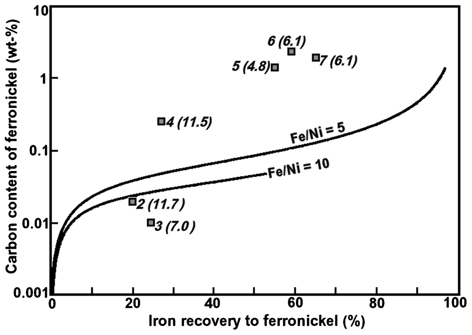
Comparison of the predicted carbon content of ferronickel with industrial data, where the Fe/Ni ratio in the calcine is given in parentheses. 2: Codemin; 3: Cerro Matoso; 4: Loma de Niquel; 5: Doniambo; 6: Pomalaa; 7: Pamco
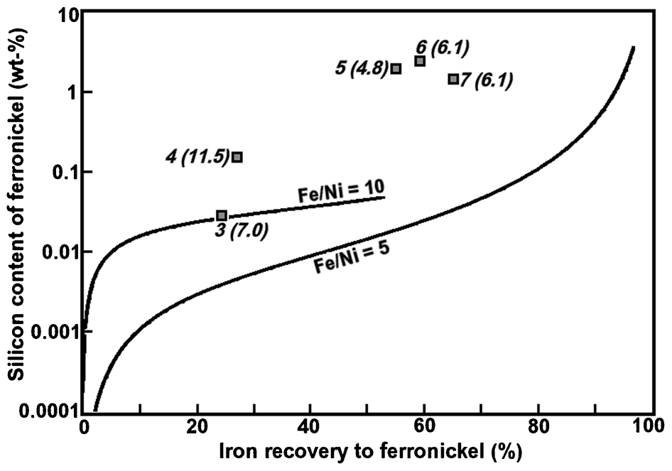
Comparison of the predicted silicon content of ferronickel with industrial data, where the Fe/Ni ratio in the calcine is given in parentheses. 3: Cerro Matoso; 4: Loma de Niquel; 5:Doniambo; 6: Pomalaa; 7: Pamco
The recovery of nickel as a function of iron recovery is shown in Fig. 20. The furnace nickel recoveries from the smelters vary from 2 to 7% below the predicted value, with those for the high iron reduction smelters being closest to the predicted values. While the recovery data from the smelters are subject to error because of sampling difficulties, the discrepancy between predicted and reported values is mostly likely because of mechanical losses of ferronickel as suspended droplets in slag, as discussed in detail by Solar (2009). Another contributing factor is disequilibrium between slag and metal in the furnace because of poor mixing. Urquhart et al. (1976) performed tracer studies on an EF used for smelting copper–nickel concentrates and found that the dead volume in the slag was about 34%. Utigard (1994) commented that there must be a significant temperature gradient through the slag in a ferronickel furnace, and it was expected that ‘the slag in the vicinity of the metal/matte interface is significantly colder, is fairly stagnant, and may be of different composition than the bulk of the slag.’ He also calculated that the degree of electromagnetic stirring in the slag was not great, leading to the likelihood that the dead volume in the slag in a ferronickel furnace is relatively large.
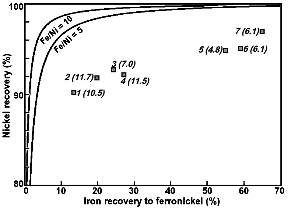
Comparison of nickel recovery with industrial data, where the Fe/Ni ratio in the calcine is given in parentheses. 1: Falcondo; 2: Codemin; 3: Cerro Matoso; 4: Loma de Niquel; 5: Doniambo; 6: Pomalaa; 7: Pamco
Conclusion
The simple computational thermodynamics model developed in this work, and applied to two representative model calcine compositions, has been shown to predict smelter outcomes satisfactorily. The most notable failure of the model is related to the carbon and silicon contents of low-grade ferronickels from calcines with low Fe/Ni ratios. The model predicted that high silicon and carbon contents should only be found in ferronickels with much higher iron recoveries than those observed in practice. This failure is shared by other models and no reason could be advanced to explain the discrepancies. Despite this, it is concluded that the simple model is an effective educational aid to achieving an understanding of laterite smelting to ferronickel.
Footnotes
Acknowledgement
The author expresses his deep appreciation to Dr Maurice Solar, Senior Metallurgical Consultant, Non-Ferrous at Hatch Ltd, for many invaluable comments, for his insights into laterite smelting, and for reviewing the draft manuscript. He also thanks the Head of the School of Civil, Environmental & Chemical Engineering at RMIT University for the provision of the facilities needed to carry out the work.