
Abstract
The favourable physicomechanical characteristics of nickel have resulted in its wide application in various products, around 2m t year−1. Nickel is an essential alloying element in austenitic stainless steel and other speciality alloys. The drastic increase in production of such alloys over the last decade, mostly because of economical growth of Asian countries, particularly China, has resulted in a considerably increased demand for ferronickel. To fulfil such an expanding industrial demand, newer and more efficient routes for extraction of nickel from poorer and more difficult ores are required. The current paper summarises years of experience in designing, operating, and optimising ferronickel smelters, and describes how this knowledge can be used to develop the mitigation measures necessary to address some of the foreseeable smelting challenges associated with metal extraction from low-grade and previously undesirable laterite ores.
Introduction
The abundance and geology of nickel in the earth's crust, its metallurgical history and economic importance have been discussed by numerous authors over the years (Bolt, 1967; Elias, 2002; Halikia et al., 2002; Mudd, 2009; Makinen and Taskinen, 2008; Rhamdhani et al., 2009a, 2009b; Kobayashi et al., 2011) and more recently by Bunjaku and coworkers (2011, 2012a, 2012b), and Swinbourne (2014). However, the current paper focuses on smelting of laterites; hence, nickel production from other sources and/or by other methods will not be discussed. Laterite deposits are formed by weathering of ultramafic rocks, which are complex mixtures of ferromagnesian minerals such as olivine (Fe, Mg)2SiO4, pyroxene (Fe, Mg)2Si2O6 and amphibole (Fe, Mg)7Si8O22(OH)2 (Dalvi et al., 2004). Consequently, the deposits are predominantly found in wet tropical areas such as Cuba, Indonesia, New Caledonia, the Philippines and South America. Exceptions are the ‘dry’ laterites found in Australia. Most laterite deposits can be divided into three layers of potential economic interest, namely:
Limonite: Goethite (FeOOH, also written as Fe2O3⋅H2O), haematite and sometimes magnetite are the main minerals. Nickel grades are usually between 1·0 and 1·5 wt-%. This layer is rather homogeneous.
Saprolite: Garnierite (Ni, Mg)6Si4O10(OH)8 is the main nickel-bearing mineral with grades of up to 10 wt-%Ni. Saprolites are quite heterogeneous and contain many other minerals with no nickel or less nickel than garnierite. Their overall nickel grades are around 1·8–2·5 wt-%.
Transition: Lies between saprolite and limonite.
Conventional wisdom is that limonites must be leached and saprolites must be smelted (Crundwell et al., 2011). But these are economic rather than metallurgical imperatives. For example, Larco in Greece is (and the ferronickel plants in Macedonia and Ukraine were) smelting nickeliferous haematite with a composition very similar to limonite, and Goro in New Caledonia was designed to pressure acid leach the totality of the ore body, the bottom third of which is saprolite.
One characteristic of these deposits is that nickel is distributed on an atomic scale within the nickel-bearing minerals and that, unlike sulphides, these minerals cannot be concentrated by conventional mineral dressing techniques. Some upgrading can be achieved by screening out the coarser fractions or, in a few rare cases, by heavy media separation. The ores may contain up to 40 wt-% free H2O but are typically of 25–35 wt-% moisture and up to 12–13 wt-% crystalline water. Pyrometallurgical processing of such wet ores requires drying, calcination and smelting of all of the upgraded material, and refining of the resulting ferroalloy, each step being quite energy intensive. Moreover, the increased demand for nickel (mostly Chinese) over the past decade has meant that the deposits being brought into operation are lower grade, often with undesirable SiO2/MgO ratios, high goethite and thus high Fe/Ni ratios, and high alumina concentrations. These ores pose new practical challenges to operators. A few of these involve the kilns; for example, the presence of more and more free silica and goethite limits the calcine temperature that can be achieved without sintering. Most of the challenges, however, involve operation of the electric furnaces. The current paper will therefore focus on some of the difficulties faced in the smelting process.
Major challenges
The first important consideration is that not all potential ores can (or should) be smelted to an arbitrarily pre-selected ferronickel grade. Table 1 and Fig. 1 show the wide variety of ferronickel grades that operators have chosen to produce. It is evident that ferronickel smelters fall within two groups: low reduction smelters that reduce about 15–30% of the iron in their ores, and high reduction smelters that reduce about 45–65% of their iron. Nickel pig iron (NPI) is simply an extension of the latter case, with NPI producers pushing the extent of iron reduction to the 70–80% range. Larco and Buruktal are examples for which the limitation is physical: ferronickel at 20 wt-%Ni cannot be produced directly from ores about 1 wt-%Ni and 30: 1 Fe/Ni ratios (Zevgolis, 2004), at least not without excessive nickel losses to the slag phase. Larco produces a ferronickel at about 12 wt-%Ni in its furnaces and upgrades this to about 18–20 wt-%Ni, by oxidising iron in an oxygen converter. Cerro Matoso S.A. (CMSA) is an example for which the limitation is economical. It is in a relatively remote location, far from nickel users; therefore, it is advantageous to produce a high-grade ferronickel and thereby reduce smelting, refining and product transportation costs.
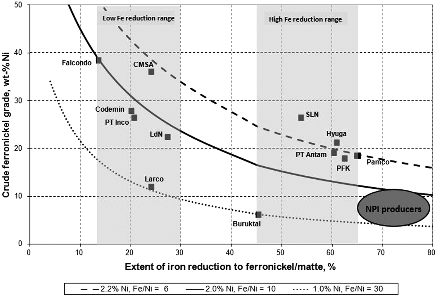
Ferronickel grades v. extent of iron reduction for different laterite smelters
Selected laterite smelters – Essential information
Every new project should therefore start with a determination of its optimum ferronickel grade, as described by Solar et al. in 2008. This determination requires the following steps.
Determination of the economically optimum ferronickel grade
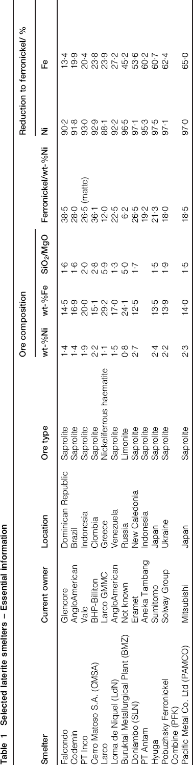
Operators are aware that lower ferronickel grades result in lower nickel loss to the slag phase through both lower nickel contents in the slag and lower slag volumes (because more iron reports to the ferronickel phase). However, higher reductions require more reductant and more power per tonne of calcine smelted. Lower ferronickel grades thus typically result in lower ore throughputs, as most smelters are furnace limited. Therefore, for any given ore and smelter, there is a maximum nickel production level, where increasing recovery is counterbalanced by decreasing ore throughput. Figure 2 summarises these correlations as function of the extent of iron reduction for an ore at 1·6 wt-%Ni, 16 wt-%Fe, and 2·2 SiO2/MgO. Note that the sudden change in the slope of the slag mass curve, at around 45% iron reduction, is because of dissolution of silicon in the ferronickel produced, the behaviour of which has been discussed earlier by Solar et al. (2008). Operating costs also vary widely from location to location. The costs specific to a given location must be determined, taking into account the cost of the ore itself (whether it is mined on site or purchased from third parties), labour, power, fuel, reductant and other commodities costs, closeness to market, etc. Revenues must then be estimated. That is relatively easy in the case of nickel, but what about iron? Ferronickel producers typically do not receive any credit for the iron contained in their final product, unless the nickel market is very tight and customers are anxious to ensure supplies. However some producers, particularly in China, are affiliated with stainless steel plants and highly value the ‘free’ iron content.
Nickel grade, recovery, production and masses of slag and ferronickel are correlated with the extent of iron reduction
Combining these three sets of calculations, i.e. mass balances, operating costs, and revenues, into a net present value for a series of potential ferronickel grades yields curves with maxima, which depend mostly on the iron credits assumed. The grade corresponding to the maximum calculated for the most likely iron credit is the ‘economically optimum’ ferronickel grade.
Assessment of metallurgical feasibility of this optimum grade
This step involves estimating a multitude of operating parameters such as the liquidus temperatures of the ferronickel and slag phases, the required ferronickel and slag superheats and operating temperatures, the potential stability of the operation, the likelihood of silicon reversals and carbon boils, etc. The selection of the target ferronickel grade for a new project is thus a compromise between the economic optimum for a given ore/smelter and the likely stability and longevity of operation at such a grade. Therefore, this selection cannot be made arbitrarily based on a preconceived idea of what the market prefers.
Control of ferronickel grade and impact on furnace operating stability
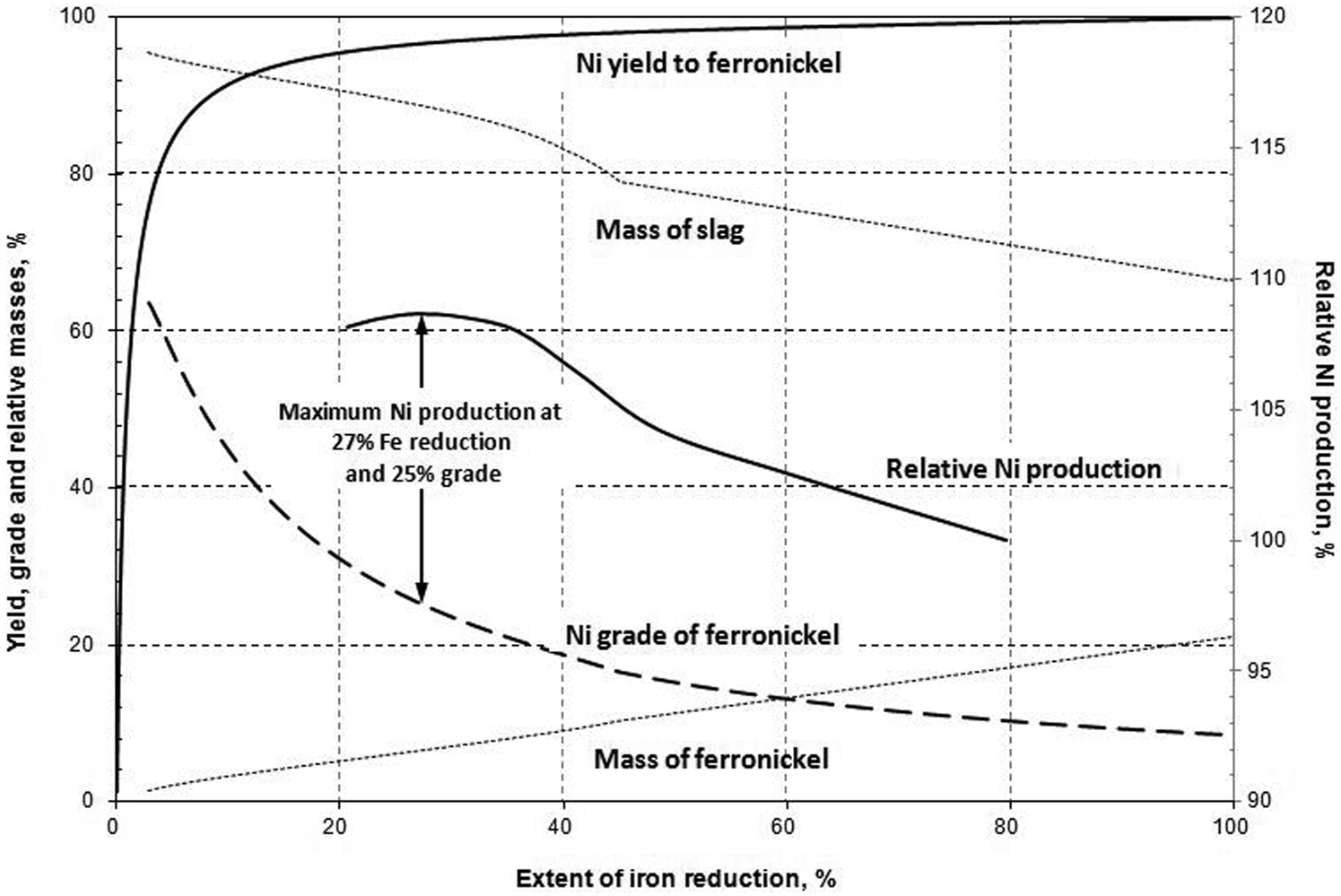
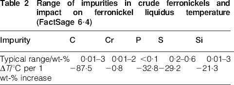
Ferronickel grades in actual operation can typically be controlled to only within ±10% relative of the target. This means that a high reduction smelter aiming at a grade of 20 wt-%Ni will actually achieve final products in the range 18–22 wt-% Ni, while a low reduction smelter targetting 35 wt-%Ni will have products varying from 32 to 38 wt-%Ni. These fluctuations can have many causes, e.g. variations in ore and coal composition and granulometry, batch addition of recycled streams such as dust, or even the ability of the feeding systems and weightometers to maintain constant proportions for all these streams. One question is then ‘What are the consequences of such variations?’ The impact of the extent of iron reduction on the levels of carbon, chromium and silicon in the ferronickel produced has been discussed at length in previous papers by the current authors (Solar et al., 2008, 2014). The relationship for carbon is represented in Fig. 3 for ease of reference. This relationship is quite important as carbon significantly decreases the liquidus temperature of ferronickel. Silicon has a similar effect, but to a lesser extent as summarised in Table 2 and Fig. 4. The liquidus temperatures were calculated using the FactSage 6·4 thermodynamic package (Bale et al., 2002; Pelton and Chartland, 2000). Note that at the nickel grades illustrated in Fig. 4 (15 and 20 wt-%Ni), a 5 wt-% increase in nickel concentration lowers the liquidus temperature of the ferronickel by 10–15°C, as addition of nickel to pure iron depresses its liquidus temperature from 1538°C down to a minimum of about 1440°C at 60–80 wt-%Ni (Sachs, 1960; Swartzendruber et al., 1991; Caccianami et al., 2006).
Carbon content v. extent of iron reduction for commercial ferronickel smelters
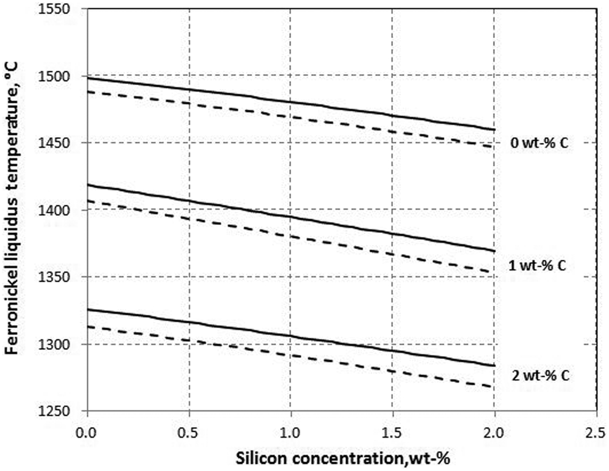
Impact of carbon and silicon on the liquidus temperature of ferronickel at 15 and 20 wt-%Ni. For each set of lines, the upper one is for 15 wt-%Ni and the lower one for 20 wt-%Ni (FactSage 6·4)
Range of impurities in crude ferronickels and impact on ferronickel liquidus temperature (FactSage 6·4)
The overall impact of the extent of iron reduction on the liquidus temperature and grade of the ferronickel produced is summarised in Fig. 5. The curves shown are calculated for an ore at 1·8 wt-%Ni, 16·5 wt-%Fe and a SiO2/MgO ratio of 2·3 (referred to as Project X hereafter), typical of many lower quality laterites that are now under consideration for development. As seen, the ferronickel liquidus temperature is reasonably constant at around 1430–1440°C in the low-iron reduction range of 15–30% while it drops slightly from 1290 to 1260°C in the high iron reduction range of 45–65%. However, between 30 and 45% iron reduction, the liquidus temperature of the ferronickel produced drops very rapidly from 1440 to 1290°C. If a ferronickel grade of 20 wt-%Ni was targeted for such an ore (requiring an iron reduction of 40%), the expected fluctuations in grade, from 18 to 22 wt-%Ni, could be caused by iron reductions fluctuating between 36 and 45% and, hence, ferronickel liquidus temperatures could vary from 1300 to 1425°C. If the furnace power, secondary voltage and electrode current were selected to yield a ferronickel operating temperature of 1440°C (53°C superheat for ferronickel at 20 wt-%Ni), the actual ferronickel superheat would vary from 140°C for ferronickel at 18 wt-%Ni down to 15°C for ferronickel at 22 wt-%Ni. These variations result mainly from the changes in carbon content of the ferronickel produced, which increases from 0·3 wt-% at 22 wt-%Ni to 1·8 wt-% at 18 wt-%Ni. Such drastic changes in ferronickel liquidus temperature would have significant impacts on operations, from increased build-up on the tapping launders at lower superheats to shortened tap block life at higher superheats. Downstream operations will also be affected; for example, shotting of ferronickel after refining requires a superheat of about 160°C to be carried out safely without steam explosions (Zamallos et al., 2009). The 18 wt-%Ni ferronickel would already have a superheat of 140°C when leaving the furnace, but the 22 wt-%Ni ferronickel would require extensive heating because its superheat would be only 15°C. Of course, these fluctuations would be dampened somewhat by the large metal inventory in the furnace. However, the drastic drop in ferronickel liquidus temperature that could be experienced when operating in the 30–45% iron reduction range may explain why no commercial smelter currently operates in this region on a steady-state basis.
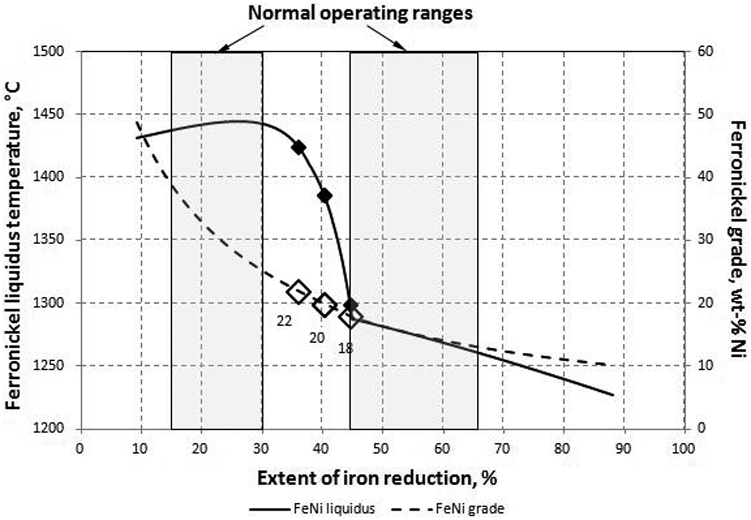
Overall impact of extent of iron reduction on liquidus temperature of ferronickel. Ferronickel grades and liquidus temperatures of 18, 20, and 22 wt-%Ni ferronickels are marked
Protection of sidewalls
Another consideration in selecting the ferronickel grade for a new project is the conditions that will be faced by the furnace sidewalls, particularly in the tidal zone at the slag/ferronickel interface. Modern ferronickel furnaces are equipped with extensive sidewall cooling (e.g. Nelson et al., 2004; Walker et al., 2009) and depend on frozen slag to protect the refractory that remains once thermal equilibrium has been reached on the walls. The tidal zone is defined as the area that sequentially faces ferronickel and then slag as ferronickel is tapped intermittently. Protection of this area is essential as it is typically where the sidewalls suffer the fastest refractory wear. This problem is especially serious when the operating temperature of the ferronickel is higher than the liquidus temperature of the slag: any slag frozen on the sidewall would then be re-melted when the metal inventory is rebuilt after a tap. Figure 6 illustrates the conditions experienced at two well-established smelters, CMSA and Société Le Nickel (SLN), and those possible for the hypothetical Project X. These conditions are detailed in Table 3 together with ferronickel and slag superheats, temperature differences and the freeze lining margins.
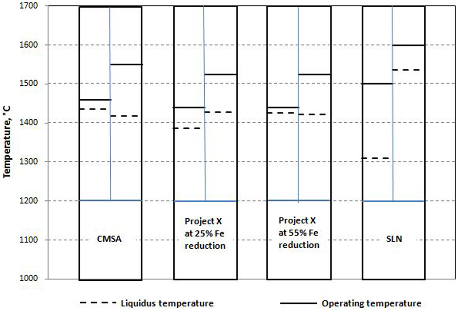
Liquidus temperatures and operating temperatures under various conditions. Ferronickel temperature on left side of each column and slag temperature on right side
Liquidus temperatures and operating temperatures (°C) under various conditions
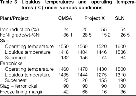
SLN is well known for smelting the best saprolite ore available: high nickel grade (>2·6 wt-%), low iron (12·5 wt-%) and excellent Fe/Ni and SiO2/MgO ratios (4·7 and 1·7, respectively). It is a high-reduction smelter with typical slag and ferronickel temperatures of 1600 and 1500°C and liquidus temperature of 1536 and 1310°C, respectively (Solar and Davenport, 2014). Its freeze lining margin, defined as the difference between the slag liquidus temperature and the ferronickel operating temperature is 36°C, assuring that slag frozen on the tidal zone of the sidewalls remains frozen when submerged in ferronickel. Cerro Matoso S.A. also had a high nickel grade ore of >2·2 wt-%, medium iron concentration of around 15 wt-%, and a medium Fe/Ni ratio of 6·8, but the highest SiO2/MgO ratio of all saprolites at 2·8, before this ore ran out almost 2 years ago and CMSA started to smelt a lower grade ore with an SiO2/MgO ratio of 1·8. It was a low reduction smelter with typical slag and ferronickel temperatures of 1550 and 1460°C, and liquidus temperature of 1418 and 1435°C, respectively. Its freeze lining margin was negative at −42°C. Therefore, special attention had to be paid to cooling of the tidal zone (Voermann et al., 2004). Two cases are shown for Project X, for low and high iron reductions of 25 and 55% as achieved at CMSA and SLN, respectively. Project X has a SiO2/MgO ratio of 2·3, meaning that its slag composition falls right in the middle of the eutectic trough in the ‘FeO’–SiO2/MgO pseudo-binary phase diagram (see Fig. 7). Several points are worth noting at this stage:
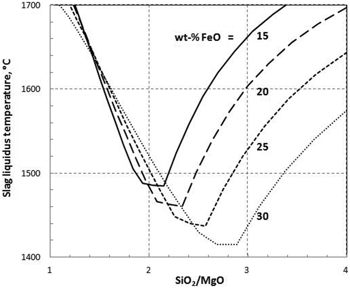
Estimate of slag liquidus temperatures for ‘FeO’–SiO2–MgO system (FactSage 6·4)
The hypothetical Project X would yield very different ferronickel grades than CMSA and SLN at the levels of iron reduction targeted in these two plants as a consequence of the different Fe/Ni ratios in the various ores. Operators are well aware of this dependence, but many project developers nevertheless select their ferronickel grade based on perceived market demand or a desire for ‘free’ iron, whether or not this choice results in a proven extent of iron reduction for the deposit under consideration. As explained above, a 20 wt-% Ni target for Project X would put the electric furnace in a potentially unstable operating window.
The difference between the operating slag and ferronickel temperatures is about the same for these two very different operations: 100°C for SLN and 90°C for CMSA, which is typical of a steady-state operation. This is the reason why this parameter was maintained at 90°C for the Project X calculations.
Cerro Matoso S.A. has a high slag superheat (132°C) and a low ferronickel superheat (26°C). The reverse is true for SLN (64 and 190°C, respectively). Both these trends were maintained for the Project X calculations.
The freeze lining margin for SLN is 36°C, but the ferronickel superheat is 190°C. With such a high ferronickel superheat, the refractory would be quickly penetrated by ferronickel if it was not protected by a frozen slag layer. On the other hand, CMSA has a negative freeze lining margin but its ferronickel superheat is only 25°C. At such a low superheat, ferronickel does not penetrate very far into the refractory and the tidal zone can survive a long time without being covered all the time with a frozen slag layer, especially when protected with powerful waffle coolers (Voermann et al., 2004).
The hypothetical Project X developer, therefore, has to choose between targetting ferronickels at 28 or 15 wt-%Ni in order to fall within the 15–30% or 45–65% iron reduction ranges. Considering that the SiO2/MgO ratio of the deposit under study falls within the eutectic trough of the ‘FeO’–SiO2/MgO pseudo-binary system, this may be a case where stability and longevity of furnace operation would lead to selection of a high iron reduction, irrespective of what the economically optimum grade might be. The consequences of such a selection would be:
limit the amount of FeO in the slag, thus increasing its liquidus temperature
increase the amount of carbon in the ferronickel produced, hence decreasing its liquidus temperature and the required operating temperature
create a positive freeze lining margin, allowing a permanent frozen slag layer in the slag/ferronickel tidal zone.
Fluxing
A commonly used method to adjust the liquidus temperature of many different types of slag is fluxing. Figure 7 appears to point in two different directions: add MgO to move up to the left-hand side of the trough or add SiO2 to move to the right-hand side of the eutectic. However, magnesite (or dolomite) is expensive, and no commercial ferronickel smelter adds magnesium carbonate or magnesia as a flux to its electric furnaces. On the other hand, high SiO2 acidic slags are aggressive on unprotected refractories (Daenuwy et al., 1992) and no commercial laterite operation adds silica deliberately. That is not to say that high MgO and high SiO2 slags cannot be processed effectively on a commercial scale: Loma de Niquel (LdN) and CMSA are examples of successful operations at these two extremes, with SiO2/MgO ratios of 1·3 and 2·8, respectively (Warner et al., 2006). However, the high MgO or SiO2 contents in these operations occur naturally in the ores smelted. This leaves limestone as the only practical flux for ferronickel operations. This practice was quite common in earlier times, but the development of advanced sidewall cooling has eliminated this approach in most modern smelters. PT Aneka Tambang, on the island of Sulawesi in Indonesia, is a good example of this development: limestone is still used on their FeNi-1 furnace, but is no longer added to the two modern FeNi-2 and FeNi-3 furnaces designed by Hatch (Bergman, 2003; Nelson et al., 2007). Pobuzhsky Ferronickel Combine (PFK) in Ukraine still uses limestone, and this practice is particularly favoured by Chinese ferronickel and NPI producers (Guo, 2009). Larco in Greece also has high levels of CaO in its slags, but these high levels come from the ores, which assay from 2 to 6 wt-%CaO, compared to <1 wt-% for normal laterites (Zevgolis, 2004).
The influence of CaO on slag viscosity and liquidus temperature has been previously studied by several authors (Chen et al., 2004, 2005; Somerville et al., 2004; Jak and Hayes, 2010). Figure 8 shows the impact of Al2O3 and CaO on the liquidus temperatures of magnesium silicate slags containing 20 wt-%FeO, calculated using FactSage 6·4. The dramatic effect of Al2O3 on slag is evident: the liquidus temperature is lowered significantly, especially on the right-hand side of the eutectic, and the eutectic itself is moved to higher SiO2/MgO ratios. Addition of CaO to the system further accentuates these trends; however, it increases the liquidus temperature of the system at intermediate SiO2/MgO ratios. As an example, the effect of limestone addition to the calcine of Project X is shown in Fig. 9. As seen, addition of 10 wt-% limestone increases slag liquidus temperature by 30–40°C depending on the grade of ferronickel assumed (which defines the FeO content of the resulting slag). The main question is: ‘Is it worth it?’ There are several reasons to avoid limestone additions, besides the obvious extra operating costs. Addition of, for example, 10% flux dilutes the feed by 10% and reduces the nickel throughput in a given smelter by about 6%, as most smelters are furnace limited (Solar et al., 2008). This 6% reduction is the minimum experienced. If the limestone is not completely calcined in the reduction kiln, the decrease in throughput is greater than 6%. However, limestone requires a temperature of at least 900°C to be calcined effectively within a reasonable length of time. That is the temperature at which ΔG° for the reaction CaCO3 = CaO + CO2 is zero. Further, the residence time required at 1000°C is a minimum of 30 min depending on the source of the limestone (Moffat and Walmsley, 2006; Muazu et al., 2011). Consequently, industrial lime producers use temperatures in excess of 1000°C (Metso Minerals Industries, 2014). The composition of the difficult laterite ores discussed here typically limits the reduction kilns to calcine temperatures of around 750°C. This is because of the presence of significant amount of goethite FeOOH and free silica in these ores. When such a material is reduced, the resulting FeO combines with the free silica to form end-members of the olivine solid solution, mainly fayalite (Fe2SiO4). These compounds have a minimum melting point of 1177°C, sintering of which starts at about 800°C (Daenuwy and Dalvi, 1997). Bulk calcine temperatures are, therefore, limited to about 750°C. Consequently, limestone is not decomposed in these kilns, and the calcines produced have high loss-on-ignition (LOI) contents. Such calcines can lead to serious slag foaming episodes when fed to electric furnaces in which insufficient charge banks do not allow for complete calcination of the limestone before it enters the slag phase. Therefore, the smelters that are still using limestone have to run their kilns with an oxidising atmosphere (which permits higher temperatures) and increased residence times to allow for sufficient decomposition of the calcium carbonate. These requirements decrease the ore throughput that would otherwise be possible and increase the energy requirements on both kilns and furnaces.
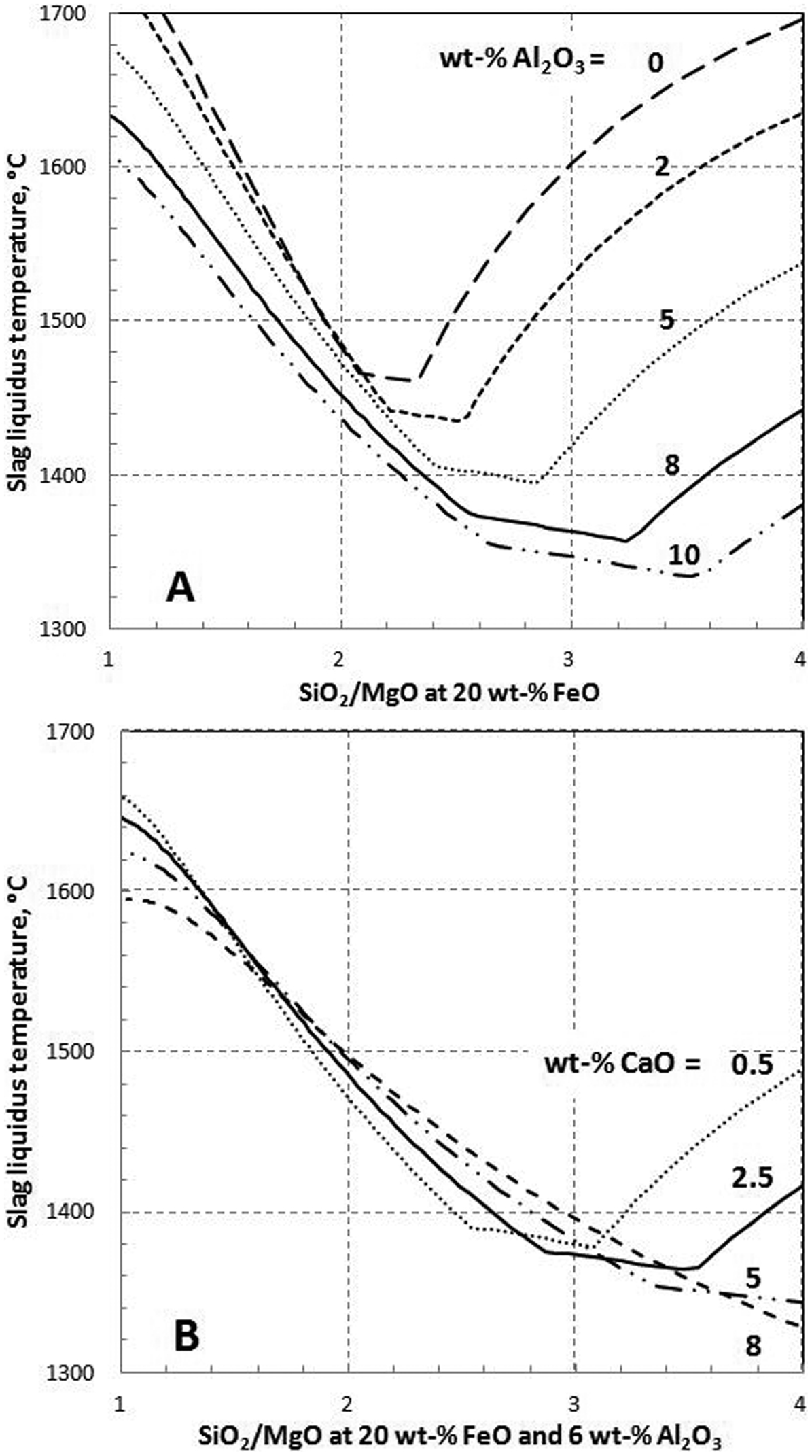
A Influence of Al2O3 on liquidus temperature of slag at 20 wt-% FeO; B Influence of CaO on liquidus temperature of slag at 20 wt-%FeO and 6 wt-%Al2O3 (FactSage 6·4)
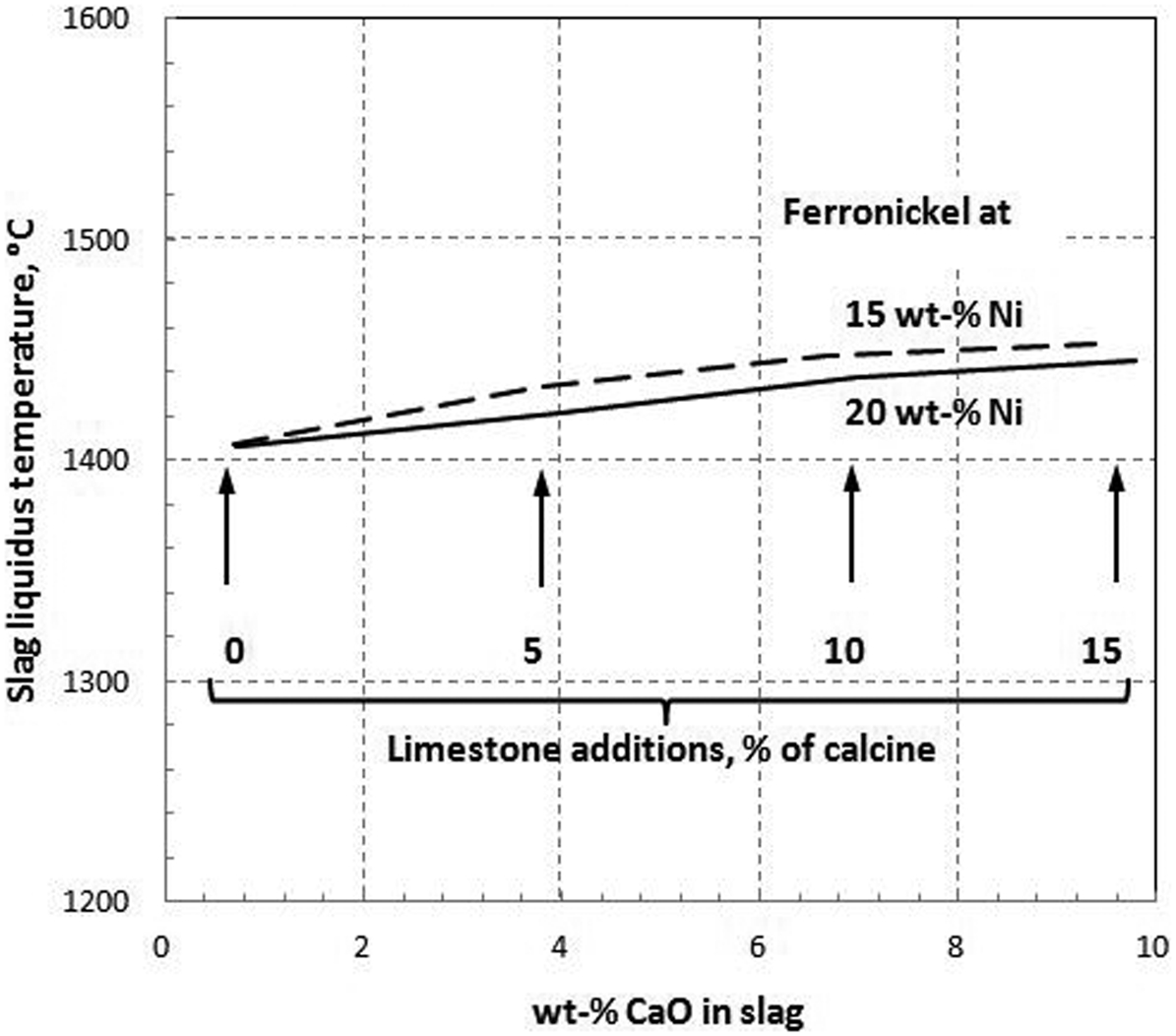
The effect of limestone additions on slag liquidus temperature of Project X, producing 15 and 20 wt-%Ni ferronickel (FactSage 6·4)
Considering that the furnace sidewalls can effectively be protected with modern cooling systems, it is not surprising that most smelters have abandoned this fluxing practice.
Phosphorus distribution
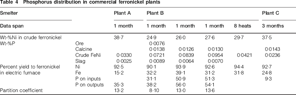
Phosphorus is an impurity that has recently become a concern for smelters, as some of the new deposits under consideration contain significant amounts of this element. Traditional ores typically assay <0·005 wt-% phosphorous and are not analysed for this element on a routine basis. Nor are the slags tapped from the electric furnaces. The ferronickels tapped are analysed for phosphorous, and a de-phosphorisation step is included in the refining process if they contain more than the 0·02–0·03 wt-% phosphorous quoted as maximum in the ISO ferronickel specifications (ISO 6501, 1988). To the best knowledge of the current authors, no detailed information has ever been published on the distribution of phosphorus in commercial ferronickel plants. Bergman (2003) quoted phosphorous assays for some electric furnace ferronickels before refining, but not the corresponding slag and ore (or calcine) assays. Otherwise, the information published refers to the refining process (e.g. Zamallos et al., 2009) or refined ferronickels (e.g. Warner et al., 2006). Pagador et al. (1999) have published data on the results of laboratory equilibration experiments between nickel alloys and MgO-saturated or CaO-fluxed iron–silicate slags. These authors reported their results in terms of distribution ratios, defined as Lx = (% X)/[% X] (where parentheses represent concentrations in slag and brackets represent that in ferronickel); whereas, the industry usually refers to partition coefficients, the inverse of the distribution ratios. The phosphorous data of Pagador et al. (1999) show an increase in partition coefficients from 0·001 to 0·2, as the oxygen potential in their systems was decreased from 10−7 to 10−9 atm. However, Solar and Davenport (2014) have shown that commercial ferronickel furnaces are not at thermodynamic equilibrium. Table 4 quotes industrial data that have recently been summarised at Hatch, Canada. The figures shown are monthly averages except in the case of the fourth set for Plant B, which gives the averages for eight individual-refining heats. It is evident that the partition coefficients for phosphorous in commercial plants range from 8 to 14, several orders of magnitude larger than the 0·001–0·2 values measured by Pagador et al. (1999) in laboratory equilibration tests. Therefore, a different approach must be developed to explain the behaviour of phosphorus in commercial furnaces.
Phosphorus distribution in commercial ferronickel plants
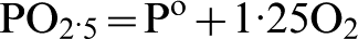
The approach proposed here is similar to that used by Jones et al. (2009) to explain the recovery of nickel, cobalt, chromium and platinum group metals (PGM) from laterites and other feeds. This mechanistic model is based on thermodynamic principles, correlating the reduction of the element under study to that of iron in the same system. The reactions can be written as
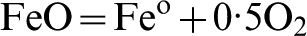
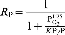
 while
while
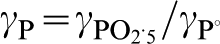
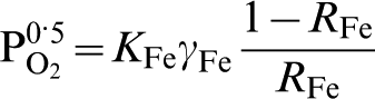
Combining equations (3) and (4) yields
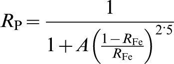
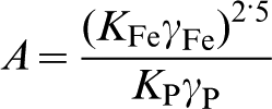
Equation (5) can then be calibrated against commercial data by determination of the A-factor using the least-squares method. Figure 10 shows the results of such a calibration, using all of the data point quoted in Table 4. The best fit was obtained for A-factor equal to 0·2.
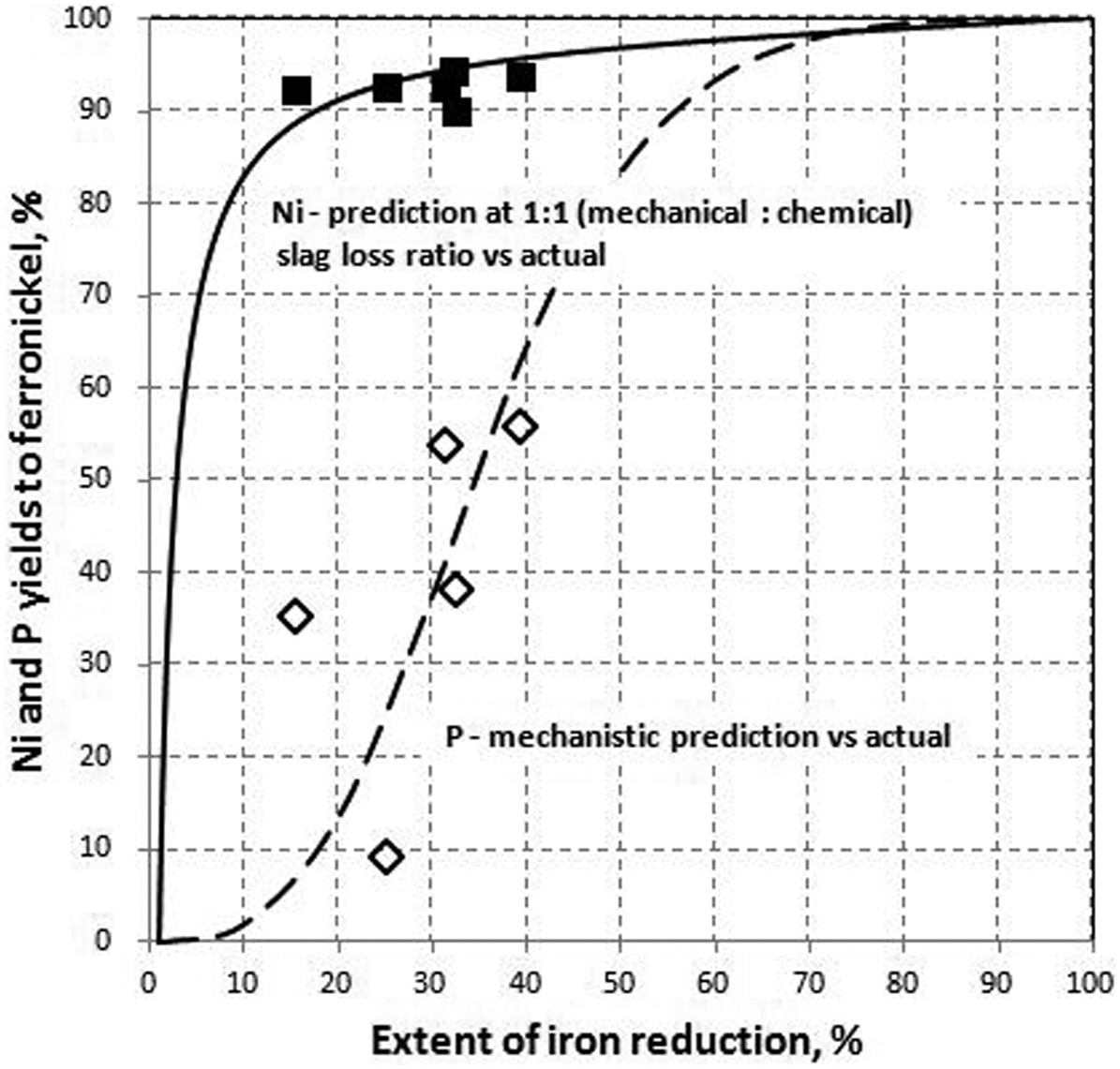
Nickel and phosphorus yields v. that of iron. Calibrated mechanistic model v. actual
Conclusions
Many of the new nickel laterite resources that are currently under consideration for development present serious challenges because of factors such as high iron contents, high SiO2/MgO ratios, and high concentrations of Al2O3, Cr2O3 and even phosphorous. This is why the authors referred to them as ‘difficult’. Selection of the ferronickel grade that will be targeted by such projects cannot be based on perceived market preferences or a desire for ‘free’ iron units. A holistic approach must be used that balances the preferences of the developer with the economical optimum for the project and what is metallurgically feasible.
Particular attention must be paid to the level of iron reduction and the difference between the slag liquidus temperature and ferronickel operating temperature. The level of iron reduction is important as it controls the amount of carbon reporting to the ferronickel phase and, consequently, its liquidus temperature. There is a drastic drop in this liquidus temperature from ∼1440°C to less than 1290°C in the 30–45% iron reduction range because of an increase in carbon content from ∼0·1 to ∼2 wt-%. Such a significant dependence of the liquidus temperature on the extent of iron reduction could lead to serious operating instabilities, which may explain why no commercial plant operates in that reduction range. The difference between slag liquidus temperature and the ferronickel operating temperature dictates whether the tidal zone at the slag/ferronickel interface is protected by freeze lining or not and, consequently, the design of the cooling systems in that area of the furnace sidewalls. Some nickel smelters, especially ex-Soviet and Chinese operations, flux with limestone as remediation for the difficult slags that may be experienced. However, fluxing with limestone presents its own challenges: it reduces the nickel concentration of the feed material (already low-grade ores), is difficult to calcine properly at the kiln temperatures that must be maintained, and its use may hence lead to serious foaming problems in the electric furnace. Modern ferronickel smelters have abandoned this practice, as the sidewall cooling systems now available have made it redundant. In addition, these ‘difficult’ ores often also contain significant quantities of phosphorus, the distribution of which between ferronickel and slag can be calculated using a calibrated mechanistic model.
Footnotes
Acknowledgement
The authors wish to thank Hatch Ltd for their support and collaboration during the performance of this review. The comments of Dr Bert Wasmund on the manuscript are gratefully appreciated.