
Abstract
In order to gain better insights into the complex mechanisms at play under fully confined blasting conditions in mining applications, several models were constructed and analysed using the hybrid stress blasting model (HSBM). A disturbed zone or microdamage criterion was proposed and used in the modelling analysis. It combined a lattice bond contact tensile failure criteria and a simple peak particle velocity based approach. Estimates were made of the extent of fracturing, disturbed and interaction zones from fully confined blastholes spaced at distances of up to 18 m, simultaneously initiated with primers positioned every 8 m. Continuous interaction was evident along the explosive column at spacings of <15 m. When blastholes were spaced at 18 m, the attenuation of the stress wave showed only partial or limited interaction along the column. With regards to the influence of in situ stress magnitudes in the range of 500–1500 m, modelling results appeared to capture the impact of stress intensity on the final extension of the macrofracturing zone. At depths of 1200 m and above, the degree of continuous interaction was diminished at the level of the initiating primers. For the simulated geotechnical conditions, the orientation of radial fractures with respect to the principal stress direction is more evident at anisotropy ratios greater than two. However, the extent and shape of the disturbed zone does not appear to be influenced by anisotropy, which showed a deficiency in the implementation of in situ stresses in the current modelling framework and further work is being conducted to address this limitation.
Introduction
The physical processes or associated mechanisms of near field rock disturbance from fully confined detonating cylindrical charges, equivalent to the detonation of fully coupled and fully confined blastholes in mining applications, are complex and have been studied using either analytical or numerical methods. The desired outcome is being able to predict and delineate the extent and/or severity of the resulting fracturing, disturbed and interaction zones (e.g. overall macro- and microdamage) from either single or several nearby blastholes detonated either simultaneously or sequentially. Rossmanith et al. (1997), Rossmanith (2003) and Rossmanith and Kouzniak (2004) described the theoretical background and provided insight into the way in which stress waves from detonating charges can propagate, interact and finally contribute to the final extent of rock mass damage, which in this context is defined as the change of the inherent or in situ characteristics of the intact rock or rock mass which changes its engineering behaviour or response. In underground mining applications, this problem is made more complex by the presence of stresses (magnitude and orientation) as well as the anisotropic nature of properties of the confining rock mass.
The work presented in this paper focuses on quantifying the impact of both the intensity and interaction of stress waves induced by the explosive detonation process, as well as the orientation and magnitude of in situ stresses. An approach is proposed to define the radius of influence within the rock mass which can be identified as disturbed. This disturbed zone does not solely refer to a zone of intense macro fracturing near the blasthole (i.e. radial and circumferential fractures) but to a combination of both macro- and microfracturing of intact rock which can be associated with the passage and superposition of stresses from simultaneously detonated explosive charges. Several models were constructed and analysed by the authors of this paper using a numerical blasting model designated as the hybrid stress blasting model (HSBM) which is briefly described in this paper. This work formed part of an continuing blasting research theme within The University of Queensland, concerned with quantifying the impact of confined blasting on rock mass damage specifically in caving mining applications.
Hybrid stress blasting model
The HSBM can be described as a sophisticated blast modelling research tool. The code has been under development through an international collaborative research project funded by a consortium of companies comprising explosive and equipment suppliers and major mining houses. The model takes into account the mechanical properties of the intact rock, rock mass structures and in situ stresses (Furtney et al., 2009; Furtney et al., 2011). In addition the HSBM uses an in-built non-ideal detonation code to calculate the combined forces (stresses and gasses) from explosive products (Braithwaite et al., 2009).
Over the course of its development several improvements and modifications have been made to both the detonation and geomechanical modelling components in order to improve the calculation speed and the size of the problems that could be modelled.
A description of the original HSBM framework has been given by Ruest et al. (2006) and has been updated by Furtney et al. (2009). The main components and software links which have not changed since the inception of the project include:
detonation modelling: this is via ideal and non-ideal detonation models to determine explosive detonation characteristics and outputs from fully coupled and decoupled conditions. The current detonation module in HSBM is designated as Vixen. It is envisaged that this semianalytical approach may later be replaced by a direct numerical solution (DNS) approach to more accurately cater for blast confinement effects
blast layout and discrete fracture network (DFN): these include blast layout and discontinuity software tools. These enable the design of larger and more complex models and blasting layouts. However the rock breakage engine has the facilities to build relatively simple blast geometries based on built-in design templates
the rock breakage engine: the rock breakage engine in the HSBM is designated Blo-Up. It uses a combination of continuous and discontinuous numerical techniques to model detonation, dynamic wave propagation, rock fragmentation and muckpile formation.
The Blo-Up interface provides the platform for model input parameters as well as the graphical display of specific outputs. These include items such as three-dimensional graphical representations of dynamic fracturing, fragment size distributions, internal fragment damage, pressure histories and velocity histories. The mechanical aspects of the Blo-Up computational engine have been discussed in detail by Furtney et al. (2011). One of the most fundamental aspects of the code is the numerical representation of the borehole, explosive charge and rock mass.
As described by Furtney et al. (2011), the borehole explosive and near field rock are represented as an axis-symmetric continuum using the FLAC code. The explosive is represented as a special constitutive behaviour in the central zones of the FLAC region. The Vixen detonation models, described separately by Cunningham et al. (2006) and Braithwaite et al. (2009), give as input to the FLAC model the velocity of detonation (VoD), the parameters for the Williamsburg equation of state, the final reaction extent, the initial density and a reference state. Energy release in the FLAC zones representing the explosive is controlled by a programmed burn (PB) algorithm. The rock in the near field area is represented as a Mohr–Coulomb material, which is coupled to the explosive reaction products represented by the Williamsburg model. Energy released by the reaction increases the isotropic stress in the zones representing the explosive. The confining material expands in response to the increasing gas pressure, and the new confining volume is transmitted to the Williamsburg equation of state, which returns a new isotropic stress. In this way, rock and explosive are fully coupled at all times. The stemming material is modelled directly as a Mohr–Coulomb material. The mechanical calculation is fully coupled to a simplified gas flow logic representing the high pressure reaction product gas. This logic uses an equilibrium pressure parameter to simulate energy losses due to crushing of the borehole wall.
The rock mass is represented with a lattice type discrete element method, which is a simplification of the full DEM calculation cycle previously performed by the PFC3D code. The main features of the lattice approach have been described by Cundall (2011), in general terms the lattice method applies forces to point masses, which have only translational degrees of freedom, and the connecting springs have a tensile breaking strength. This simplification has resulted in an increase in calculation speed and a significant decrease in memory storage requirements. The model geometry is built up of point masses distributed in a non-repeating pattern with a user specified average separation between nodes (i.e. model resolution). On the lattice, four boundary conditions are permitted: free, quiet, semi-quiet and flex. Free nodes represent a free surface, which may reflect stress waves. Quiet boundaries are used to model intact rock of the same type in the far field. Quiet boundaries ensure that wave energy is absorbed at the interior (artificial) model boundaries. This is the boundary condition mainly used in fully confined blasting models such as those discussed in this paper.
Disturbed or damage zone criterion
A disturbed or damage zone criterion is proposed and described as a region which combines both the final state of the impacted intact rock (e.g. lattice node contact failure) and the irreversible deformation or microfracturing caused by a stress transient. This stress transient is assumed to be directly related to the radial peak particle velocity component. In this case, particle velocity is used as an index to define the potential areas of the rock mass which are likely to be disturbed by the propagation and interaction of stress waves from detonating charges which are represented in the model by field velocity contours. The application of peak particle velocity as an index to estimate damage has been previously demonstrated by researchers and practitioners (Holmberg and Persson, 1980; Onederra and Esen, 2003; Lu and Hustrulid, 2003).
Confined blasting model interpretation
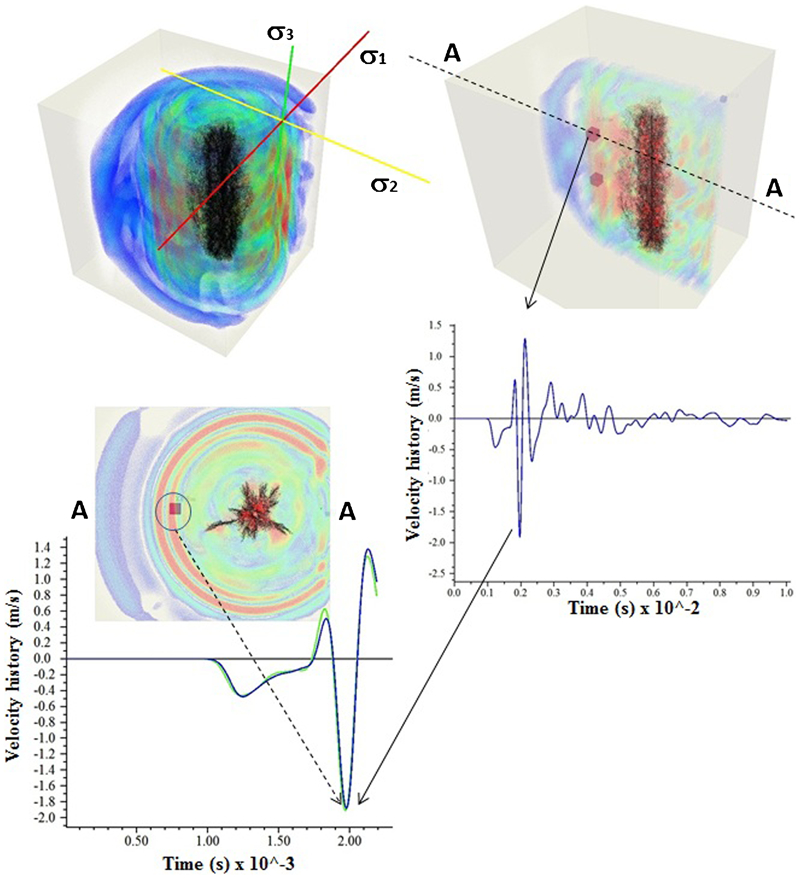
To help explain the proposed disturbed zone criterion, Fig. 1 shows a long section of a two blasthole configuration and describes the different stages and therefore the mechanisms which are assumed in order to model disturbed zones in confined blasting conditions. In this example, primers or initiation points are located every 8 m along the length of each blasthole. During stages 1 and 2, in the figure, the detonation process begins and the stress waves interact along the length of each blasthole after the consumption or detonation of ∼4 m of the explosive charge. Immediately after the interaction of the detonation fronts described in stage 2 and immediately after the explosive column has been consumed, the gas logic in HSBM is activated (stage 3). It should be noted that in the numerical approach implemented in HSBM, the combined effect of the shock and gas, produces the stress wave imparted into the virtual rock mass which is depicted in an isometric view in stage 4. This stage shows, in red, the radial velocity field with amplitudes exceeding 1100 mm s−1 after ∼1·8 ms. These particle velocities attenuate with distance and may interact with other incoming waves of adjacent charges as described in the long section depicted in stage 5. This shows that for any given spacing between charges, the positive superimposition and therefore positive reinforcement of stress or blast waves can still contribute to disturbances in the rock. The extent of this interaction will depend on the level of stress attenuation and the distance between charges, and the detonation times of these charges. As shown in stage 5, the probability of positive interaction is high for the chosen distance as the degree of disturbance is continuous along the charge and covers the volume of interest.
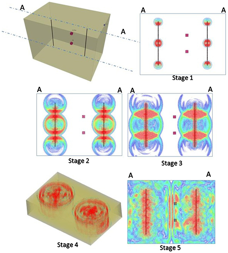
Two blasthole configuration describing main numerical modelling stages in confined blasting conditions
Fracturing, disturbed and interaction zones criterion
Figures 2 and 3 illustrate the proposed criterion which is also used to interpret the output generated by subsequent HSBM models. Currently the HSBM is only able to display the final state of a point in the rock mass represented by lattice node contacts (i.e. either failed or intact). This is not necessarily valid when identifying regions that may have experienced transient stress loads that could cause microfracturing or irreversible damage to intact rock. Because of the ability of HSBM to dynamically display velocity fields in three dimensions, this particular output was used to identify at different stages of the stress propagation and attenuation process, the potential extent of disturbed zones at given distances; and also define whether interaction or stress superposition is achieved between blastholes. An index of incipient damage of 1100 mm s−1 was estimated from average intact properties and used to display the extent of potential disturbed zones as well as interaction caused by the simultaneous initiation of confined charges. As shown in Figs. 2 and 3, this envelope is expected to have different degrees of damage, ranging from a fractured zone near the blasthole (consisting of mainly macrofracturing) to disturbed zones further away from the blasthole (consisting mainly of microfracturing of intact rock) and after the further propagation and interaction of stresses, an interaction zone is identified between blastholes.
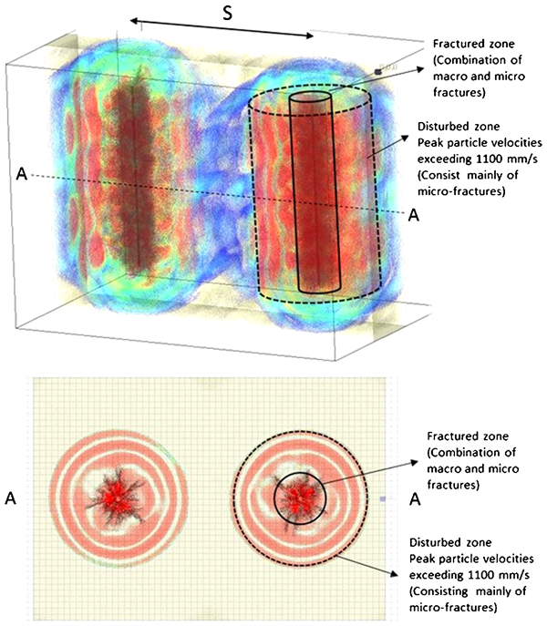
Isometric and plan section views describing criteria used to define macrofracturing and disturbed zones in proposed models
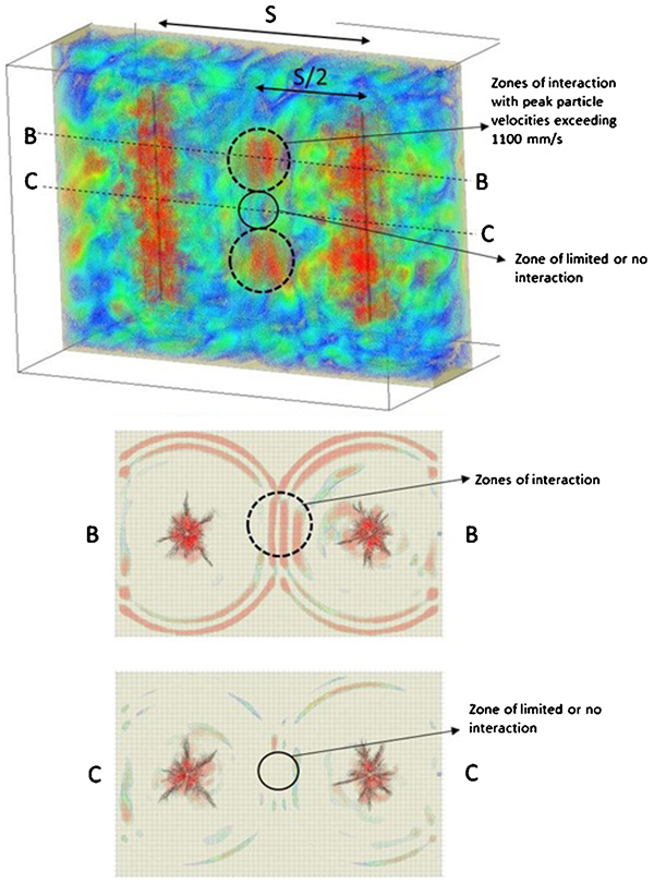
Isometric and plan section views describing criteria used to define disturbed zones from stress interaction/superposition
Hybrid stress blasting model calibration
The implementation of fully instrumented single hole tests at a large underground operation enabled the calibration, final configuration and optimisation of HSBM models discussed in this paper, further details are given by Catalan et al. (2012). The calibration process allowed the optimisation of model geometries, boundary conditions and definition of key model solution parameters. These parameters are associated with strength and strain rate dependency, lattice resolution requirements, velocity attenuation and activation conditions for the implemented gas flow logic.
Intact rock and stress field input parameters
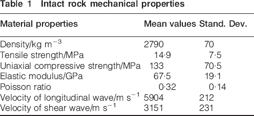
The mechanical properties which have been used as input into the HSBM numerical analyses are summarised in Table 1. These values are based on the work discussed by Catalan et al. (2012).
Intact rock mechanical properties
A damping coefficient also needs to be specified. This coefficient takes into account the attenuation characteristics of the intact rock or material such as rock fabric, mineralisation, porosity, texture or other characteristics which define its heterogeneity. Furtney et al. (2009) indicated that a damping coefficient that may be set from zero to unity. A value of zero corresponds to no-damping and a value of unity corresponds to critical damping. A value of 0·1 was assumed and was primarily based on previous research that focussed on the evaluation of this coefficient (Onederra et al., 2009).
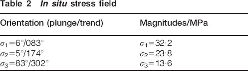
The in situ stress field which has been used as input into HSBM models is summarised in Table 2 below. This is also based on direct measurements reported by Catalan et al. (2012).
In situ stress field
Model boundary conditions and solution parameters
In fully confined conditions, quiet boundaries are used in the model configuration to ensure that wave energy is absorbed at the interior (artificial) model boundaries (Furtney et al., 2009). The lattice scheme implemented in the HSBM model consists of an assembly of point masses (or nodes), each of which is connected by springs to its neighbours. In this approach each spring operates in both the shear and normal directions. The lattice method applies forces to point masses, which have only translational degrees of freedom, and the connecting springs have a tensile breaking strength. The known dependency of tensile strength on strain rate has been implemented in the HSBM with a simple model where the tensile strength is scaled by a power law function of distance away from the nearest borehole:

Model calibration and geometric configuration
From a modelling perspective the calibration process involved an iterative process that within the context of this work had the aim of matching, as close as it is reasonably possible, radial velocity measurements at defined distances (e.g. 7·5 and 9 m away). Near field peak velocity measurements were calculated from complete acceleration records obtained during the implemented single hole trials (Catalan et al., 2012). Once a close match was obtained and the model was numerically stable, the calibrated model was configured and used to investigate the extent of disturbed zones given by different blasthole pattern layouts and in situ stress regimes.
Figure 4 shows an example of the results of a calibration test where the radial peak particle velocity is approximately 1900 mm s−1 7·5 m away from the closest explosive charge. This peak value closely matches the range of recorded values (e.g. 1000–2500 mm s−1) and was considered appropriate for modelling purposes. As shown in Fig. 4, the model peak radial velocity is due to the combined transfer of explosive energy from the FLAC explosive zone into the lattice zone (virtual rock mass). The model is stable within the test simulation timeframe of 10 ms when all wave transients have dissipated. From a practical point of view, the measured and modelled peak radial velocities are consistent with the range of peak particle velocities that can be estimated by more simplistic empirical models (Holmberg and Persson, 1980). This provided a justifiable basis for adopting the disturbed zone and interaction criterion that combines both the HSBM bond contact tensile failure criteria and a practical peak particle velocity based approach.
Results of calibration tests where radial peak particle velocity is ∼1900 mm s−1 7·5 m away from the closest explosive charge
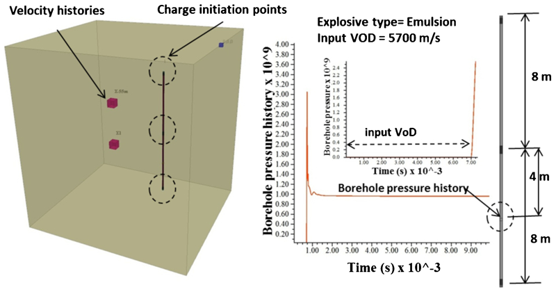
The computational intensive nature of the HSBM requires a degree of optimisation prior to the definition of final modelling parameters. Preliminary work demonstrated the repeating pattern of the damage and disturbed zones given by the dynamic decking of the explosive column from the simultaneous initiation of primers located every 8 m. From these earlier tests, the optimum model size for the current configuration was defined and consisted of a column charge with three initiation points as shown in Fig. 5. This simple configuration was able to capture key mechanisms of macro fracturing and disturbed zones due to the interaction and potential superposition of stress waves in the near field.
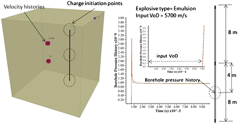
Geometry and explosive charging configuration showing borehole pressure history and with corresponding VoD input
Figure 5 also describes the output from a borehole pressure history point located inside the charge to check that the explosive's VoD is properly modelled.
Hybrid stress blasting modelling scenarios and results
For consistency, the three dimensional modelling outputs from each scenario are displayed in plan sections and long sections, where appropriate, to easily identify the radial extent of fracturing, disturbed zones and the likelihood of interaction. The analysis focuses on wave stress transients occurring within a few milliseconds after the explosive detonation process (i.e. 1·5–3·0 ms). Sections are taken at the level of an initiating primer as well as between primer positions, as will be apparent these two levels can better describe the overall extent of macrofracturing, disturbed zones and interaction. It should also be noted that all sections displayed on a 0·5×0·5 m grid with red showing peak velocities exceeding 1100 mm s−1 at a specific simulation time stage.
Scenario 1: linear and vertical blasthole interactions
As described in Fig. 6, an evaluation of the disturbed zone envelope is performed for two 165 mm diameter vertical blastholes fired simultaneously and spaced at distances of 12, 15 and 18 m respectively. The three cases considered the in situ stress field described in Table 2 which is characteristic of a depth of ∼750 m.
Parameters and blasthole distances of scenario 1 models
Results: 12 m spacing
Results from the 12 m spacing configuration are shown in Fig. 7. In this case results indicate that within ∼1·6 ms, peak radial velocities exceeding 1100 mm s−1 from individual blastholes can occur at radii of ∼5·0 m at the level of the initiating primer or 6·0 m midway between primer positions. This can be defined as the extent of the disturbed zone. The fractured zone is characterised by a number of radial fractures contained in a radius of ∼2·5 m. Modelling results also show that the likelihood of positive interaction is high at the 12 m spacing configuration. As shown by the sections taken at the potential interaction timeframe (i.e. ∼1·8 ms), continuous superposition is expected along the explosive charge, i.e. at the primer and between primers), meaning that disturbed zones between these charges is expected.
Snapshots of fractured and disturbed zones at 12 m spacing configuration
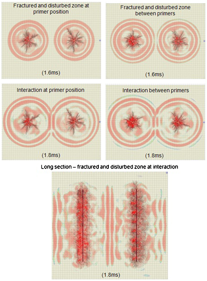
Results: 15 m spacing
Results from the 15 m spacing configuration are shown in Fig. 8. As in the 12 m spacing case, results indicate that within ∼1·6 ms, peak radial velocities exceeding 1100 mm s−1 from individual blastholes can occur at radii of ∼5·0 m at the level of the initiating primer or 6·0 m midway between primer positions. The disturbed zones from individual blastholes is consistent to the previous case; however, velocities and hence stresses attenuate further before interaction occurs. As shown in Fig. 8 at the interaction timeframe (i.e. ∼2·1 ms), continuous superposition/interaction of stresses may still be achieved along the explosive charge between initiating primers; however, a small reduction is observed at the level of the primer. In general, disturbed zones defined by the combined fractured and disturbed zone criteria may still be expected at this spacing. However, it is not as continuous between charges as in the 12 m spacing case.
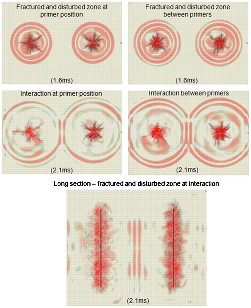
Snapshots of fractured and disturbed zones at 15 m spacing configuration
Results: 18 m spacing
Results from the 18 m spacing configuration are shown in Fig. 9. At the interaction timeframe (i.e. ∼2·3 ms) further attenuation of the stress wave however shows only partial or limited superposition/interaction along the explosive column. At the primer position there is no evidence of interaction and hence the disturbed zones extent would not be continuous at this larger spacing configuration.
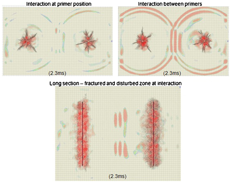
Snapshots of fractured and disturbed zones at 18 m spacing configuration
Scenario 2: influence of in situ stress magnitudes
The 15 m spacing configuration from the previous analysis was used to evaluate the impact of in situ stress magnitudes at depths of 500, 750, 1000, 1200 and 1500 m. Model configurations and corresponding stress magnitudes are summarised in Fig. 10.
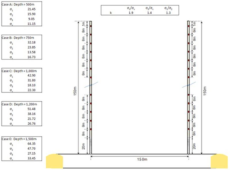
Blasthole geometry and in situ stress regime of scenario 2 models: note all stress values in MPa and orientations as per Table 2
Results: influence of in situ stress magnitudes
Figure 11 summarises the results at depths of 500–1000 m and Fig. 12 at depths of 1200 and 1500 m respectively. The analysis clearly shows the impact of depth (in situ stresses) on the intensity and extension of the macrofracturing zone. The radial extent varies from an average radius of 3·5–4·0 m at 500 m to ∼1·5 m at depths of 1500 m. The disturbed zone is also affected in terms of intensity and extent of interaction between blastholes. As shown, at depths of 1200 m and above, the degree of continuous interaction and hence disturbance potential is diminished at the level of the primer initiation point. This condition is exacerbated at 1500 m. The analysis shows that blasthole spacing may need to be altered (closer together) at greater depths (e.g. above 1200 m) to maximise the potential for interaction and thus the extent of disturbance.
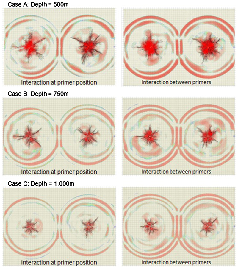
Influence of stress magnitudes on degree of interaction/superposition for in situ stress regimes of 500 to 1000 m
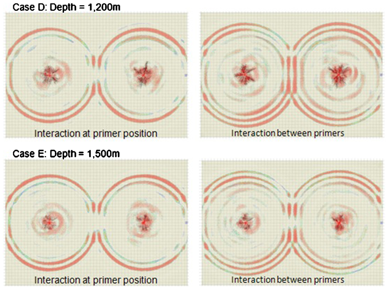
Influence of stress magnitudes on degree of interaction/superposition for in situ stress regimes of 1200–1500 m
Scenario 3: influence of in situ stress anisotropy
The aim of scenario 3 was to evaluate the impact of stress anisotropy for the range of the ratio of stresses k given in Fig. 13. In this case, the 15 m spacing configuration was adopted at a depth of 1000 m.
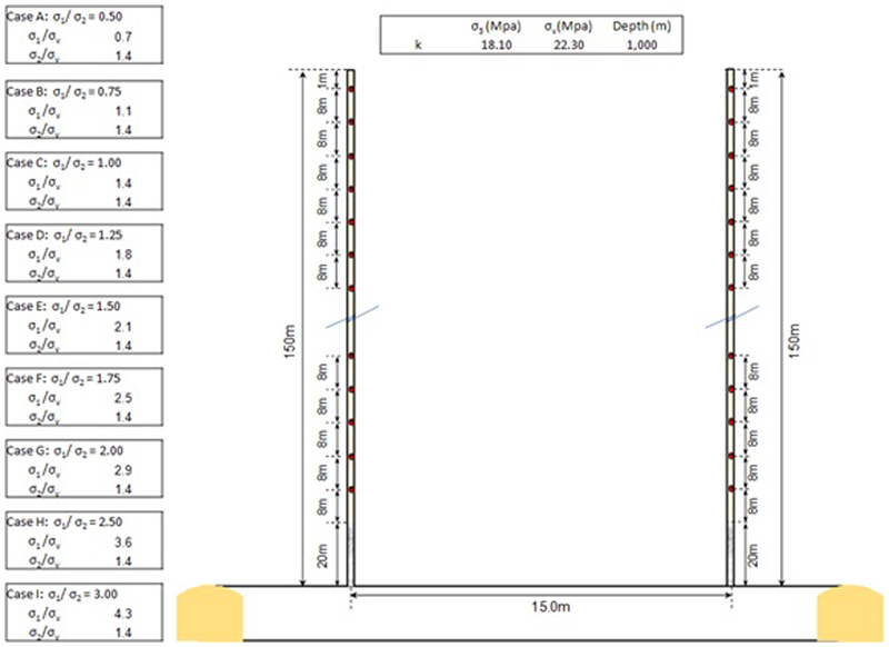
Blasthole geometry and anisotropy ratios of scenario 3 models
Results: influence of ratio of stresses
As discussed, the impact of in situ stress anisotropy was evaluated for k ratios ranging from 0·5 to 2·5 at a constant depth of 1000 m. The analysis also focused on the extent of disturbed zones at the interaction stage. Figures 14–16 summarise the results of this analysis. For the simulated geotechnical conditions, the orientation of radial fractures with respect to the principal stress direction is more evident at anisotropy ratios greater than two. However, the extent and shape of the disturbed zone does not appear to be influenced by anisotropy, which showed a deficiency in the implementation of in situ stresses in the current modelling framework and further work is being conducted to address this limitation.
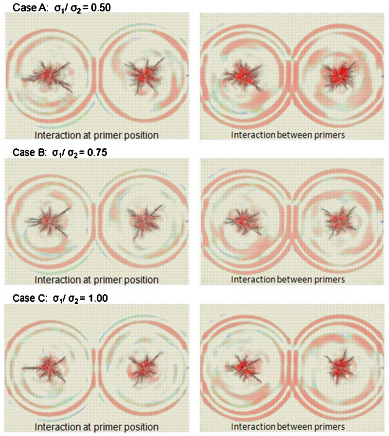
Extent of disturbed zones at interaction stage for stress anisotropy ratios of 0·5–1·0
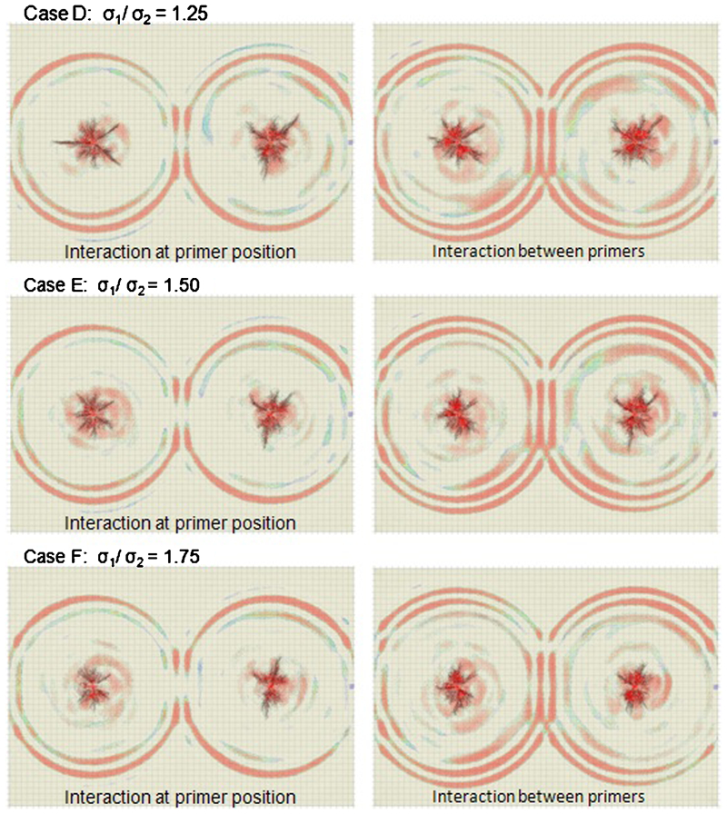
Extent of disturbed zones at interaction stage for stress anisotropy ratios of 1·25–1·75
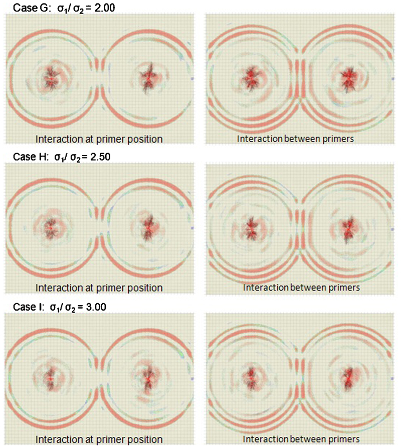
Extent of disturbed zones at interaction stage for stress anisotropy ratios of 2·0–3·0
Conclusions
To understand the complex mechanisms at play under confined blasting conditions, several models were constructed using the HSBM. A disturbed zones criterion was established and adopted in the numerical modelling analysis. This criterion combined both a lattice bond contact tensile failure criteria and a practical peak particle velocity based approach. Because of the ability of HSBM to dynamically display velocity fields, this particular output was used to identify at different stages of the stress propagation and attenuation process, the potential extent of disturbance at given distances; and also define whether interaction is achieved between blastholes. An index of incipient damage of 1100 mm s−1 was used to display the extent of potential disturbance as well as interaction caused by the simultaneous initiation of confined charges. Three zones are described which are expected to have different degrees of damage, ranging from a fractured zone near the blasthole to disturbed zones further away from the blasthole consisting mainly of microfracturing of intact rock.
A number of modelling scenarios were evaluated with the HSBM, the main conclusions from the results of the studied configurations can be summarised as follows.
The likelihood of positive interaction is high at a 12 m in-line blasthole spacing configuration. Continuous interaction/superposition was evident along the explosive charge (i.e. at the primer and between primers), meaning that disturbed zones between these charges can be expected.
When vertical blastholes are spaced apart at 15 m centres, continuous superposition/interaction of stresses may still be achieved along the explosive charge between initiating primers; however, a small reduction is observed at the level of the primer. In general, disturbed zones defined by the combined fractured and disturbed zone criteria may still be expected at this spacing.
When vertical blastholes are spaced at 18 m, attenuation of the stress wave shows only partial or limited superposition/interaction along the explosive column. At the primer position there is no evidence of interaction and is not continuous at this larger spacing configuration.
With regards to the influence of in situ stress magnitude. At 15 m spacing configuration, modelling results appear to capture the impact of depth (in situ stresses) on the intensity and extension of the macrofracturing zone. The radial extent varies from an average radius of 3·5–4·0 m at 500 m to ∼1·5 m at depths of 1500 m. The disturbed zone is also affected in terms of intensity and extent of interaction between blastholes. At depths of 1200 m and above, the degree of continuous interaction and hence disturbed zones potential is diminished at the level of the primer initiation point. This condition is exacerbated at 1500 m. The analysis indicates that blasthole spacing may need to be altered (be closer together) at greater depths (e.g. above 1200 m) to maximise the potential for interaction and thus the extent of disturbance.
For the simulated geotechnical conditions, the orientation of radial fractures with respect to the principal stress direction is more evident at anisotropy ratios greater than two. However, the extent and shape of the disturbed zone does not appear to be influenced by anisotropy, this showed a deficiency in the implementation of in situ stresses in the current modelling framework and further work is being conducted to address this limitation.