
Abstract
Potash, a fertiliser currently in demand worldwide, lies beneath beds of salt and other evaporites deep within the ground. The ground support challenge encountered when excavating through these strata is that of time dependent (creep) deformation control. The deformation is radial, causing the shaft excavation to close up over time, eventually loading the permanent lining with the full geostatic pressure and causing lining failure. In order to achieve a significant design life for an economical shaft lining in creeping rocksalt strata, a deformation zone filled with a compressible material is employed between the excavation and permanent lining. This helps resist the ground pressure, and reduce the magnitude and velocity of creep deformation. Optimum lining designs have been developed by predicting the creep deformation at a given time and by considering the behaviour of different compressible materials available to fill the deformation zone. Foamed concrete is the favoured material for an intermediate compressible lining.
Introduction
Potash is an evaporite mineral and is currently mined at depths in excess of 1 km below ground level.
Potash is a commercially important product, used as a raw ingredient in the manufacture of agricultural fertiliser, providing the potassium salt content. Global demand for potash is expected to increase, particularly as the economic growth of the People's Republic of China (PRC) continues.
In addition to the direct extraction of potash, excavation and mining in geological salt deposits provide potential repositories for the storage of materials. Particularly thick deposits of salt are found within salt domes. The rock salt in these salt dome formations is impermeable and thus creates ideal conditions for storage of hazardous waste, oil and a variety of gases, e.g. carbon capture and storage, hydrogen and natural gas (British Geological Survey, 2008). Furthermore, salt deposits exhibit creep deformation behaviour, and as such can be considered self-healing with any fractures slowly re-sealing. Useful by-products of cavern formation include table salt and rock salt for road de-icing.
The greatest challenge in the design of shaft and drift structures through evaporite deposits is the propensity for creep deformation in salt rocks.
When excavating through certain salts and evaporite deposits, the rock creep properties manifest as a pronounced squeezing effect. This is a lateral expansion of viscous salt material which is sandwiched between rigid competent rock strata. Consequently, rheological behaviour develops under the full overburden pressure of the ground, and the rocksalt slowly squeezes out into the unconfined excavation. This lateral deformation of salt rocks makes the lining design of mine shafts difficult, as eventually the full overburden pressure of the ground will be applied to the shaft structure. In most cases it is impractical and uneconomical to construct a shaft to resist this very high level of applied pressure.
Traditionally, shafts have either been lined, and subsequently overloaded, or alternatively left unlined. However, moisture in the air can decompose the face of excavated salt, and large stalactite features form. Together with the creep deformation effect of the excavation closing up, this necessitates a large amount of regular maintenance to keep the shaft environment safe and operational. Consequently, mine operators prefer to operate from a secure lined shaft environment.
Boulby is the second deepest mine in Europe extending to 2 km underground where both potash and rock salt are mined. The two 5⋅5 m diameter shafts on this site, constructed in the late 1960s, pass through an especially problematic body of squeezing rock (Carnallitic Marl) at an approximate depth of 1100 m. The shafts have been relined through this section twice, once between 1983–86 and again in 1997–2001. Reference is made to Boulby frequently in this paper due to its past design problems. Data and information from Boulby have been used in this paper to help understand the creep deformation phenomenon and to validate the design tool which was developed for creep deformation prediction.
Shaft lining design
Shaft linings are usually only designed to be either nominally structural, or to resist hydrostatic pressures. They are rarely designed to resist direct rock pressures at substantial depth, as this is only necessary when the excavation is subject to large plastic or creep deformation. Competent rocks are considered to be self-supporting when excavated, and consequently exhibit limited plastic deformation upon excavation. Typically, soils and marginally competent rocks occur at shallower depths where lateral ground pressures are more readily accommodated.
The act of excavating a shaft causes stress redistribution and thereby strains in the ground adjacent to the excavation. Predicting the length of time required for the ground stresses to redistribute is essential in order to design a suitable lining, as there is a significant risk of overloading a lining if it is installed too soon after excavation when the ground deformations are still taking place. For a standard shaft design, balancing the ground deformations with the allowable strains and induced stresses in the lining is the principal challenge.
The four principal lining types traditionally employed for shafts are listed in Table 1, however, various hybrid linings containing elements of these linings are possible.
Principal lining types traditionally employed for deep shafts
When faced with strata that exhibit time dependent deformation (creep deformation) at significant depth, the balancing of the deformations in the ground and shaft lining is ultimately not possible, as eventually, the applied ground stresses will exceed the capacity of the shaft lining. Consequently, it is important to attempt to predict the magnitude of the likely creep deformation and balance this against the intended service life of the shaft.
Elastic, plastic and long-term creep deformations occur within the ground following and in advance of excavation, however this paper concentrates particularly on creep deformation with reference to salt rock strata.
Prediction of ground creep deformation
According to Ladanyi (1980), experimental evidence shows that in general the creep behaviour of rocks is complex depending on factors such as rock type, temperature, humidity and hydrostatic pressure. When excluding the areas of very high temperatures and hydrostatic pressures, it is found that most time dependent deformation in rocks is caused by thermally activated microfracturing and transient (work-hardening) effects.
Several studies have been undertaken with the aim of defining a constitutive law that correlates applied stress and resultant deformation rate.
Creep deformation in rock salt is influenced by several factors:
Deviatoric stress (differential stress): deviatoric stresses in relation to geology being ‘a condition in which the stress components operating at a point in a body are not the same in every direction’ (Sci-Tech, 2003).
Mineral composition: all natural evaporite deposits contain impurities, rock salt contains a small amount of potash, marl, etc. It is expected that the presence of theses impurities will alter the behaviour of rocksalt.
Dislocations and defects: a dislocation is an irregularity within the rock makeup, these small defects allow the molecules to move and can alter behaviour of creeping material.
Grain size: the size of crystals within a material is known to have a significant impact on creep deformation as the material deformations occur by the displacement of individual grains. The smaller the grain size, the more grains there are and correspondingly there is greater potential for creep deformation.
Temperature: This increases with depth below ground and higher temperatures are known to speed up creep effects as the molecules have more energy with which to move.
The accurate prediction of the magnitude of creep closure in a circular shaft passing through evaporite deposits is challenging. Numerous researchers have attempted to establish a relationship between laboratory tests and the in situ creep behaviour of a rock mass. Most of the work has been related to roadway closure which has little relationship to the behaviour of the ground for a circular shaft. The simplest form of creep law after Salamon and Quinteiro (1991), which has generally been used in relation to laboratory tests, is:

Equation (1) describes a general material creep relationship, and as such is insufficient for the prediction of the closure in a circular shaft. Consequently it must be incorporated into a form that addresses thick cylinder stress theory.
Ladanyi (1980) and Klein (1985) identified the general form for radial displacement at the face of a circular shaft as
For a shaft in an infinite medium, ro is large resulting in equation (3) below.
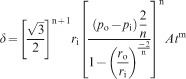
Williams and Auld (2002)
This equation can be used as a straightforward prediction of the deformation associated with a specific time. Historically it has been used to predict the Carnallitic Marl creep deformation at Boulby. This expression was derived in conjunction with a back analysis of the failed lining. The laboratory test results for the Carnallitic Marl provided values for the A, m and n constants, these suggested virtually zero deformation when input into the deformation formula. Hence, more general values associated with salt behaviour were adopted to give more realistic deformations that matched the failure performance of the previously restored lining.
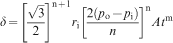
Passaris and Horseman (1982)
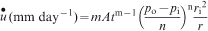
Equation (4) defines the rate of strain and therefore requires an iterative approach to evaluate the total deformation, as the excavated shaft radius constantly changes in line with the creep deformation over time.
Figure 1 shows a simplified diagram of a circular shaft passing through problematic creeping rock strata. This indicates the key geometric parameters used in equations (1–4), and how the radial displacement is relative to the differential pressures across the shaft wall.
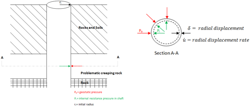
Diagram illustrating the key stress and geometric parameters used in the prediction of rock creep deformation
To date, problems have occurred at Boulby in the shaft lining through the salt section. Williams and Auld (2002) observed that the lining had cracked and buckled in places making it unsafe, and consequent to this, the shaft section of lining through the Carnallitic Marl is currently undergoing further remediation works.
Given the particular challenges of the Carnallitic Marl at Boulby, it is understood that frequent re-lining of the shafts has been incorporated into the maintenance regimen.
Compatibility of time dependent ground behaviour
The method adopted by Ladanyi (1980) has been used to predict creep behaviour of rock salt, whereby isochronous characteristic lines (lines of creep deformation at equal time) are derived to review the creep characteristics. The work carried out by Williams and Auld (2002), to determine the lining design at Boulby, has been used as a reference case. The Passaris and Horseman (1982) approach, given by equation (4), has then been checked against the Williams and Auld (2002) results from Boulby using the same input data. The results from the Williams and Auld (2002) and Passaris and Horseman (1982) approaches compare favourably with each other. Note, the Passaris and Horseman (1982) approach has been used to develop the isochronal curves included in this paper.
Passaris and Horseman approach
The creep parameters (A, m, n) for salt are extremely difficult to obtain experimentally and therefore for real world shaft designs the creep parameters have to be estimated from previous work and analysis. Consequently, analysis runs for each individual rock stratum are not considered relevant as insufficient data is available to draw any meaningful distinctions between the creep properties of the different halite materials. It is hoped that as better instrumentation is used during mine shaft sinking projects that the creep parameters can be realistically defined for the different strata.
As potash mines in Canada have similar rock geology to that of Boulby Potash Mine, it is reasonable to base the calculations of creep deformation for the new potash mine projects on this example.
Passaris and Horseman (1982) quote the creep parameters in Table 2 adjusted for a temperature of 34°C.
Salt creep parameters from Passaris and Horseman, 1982
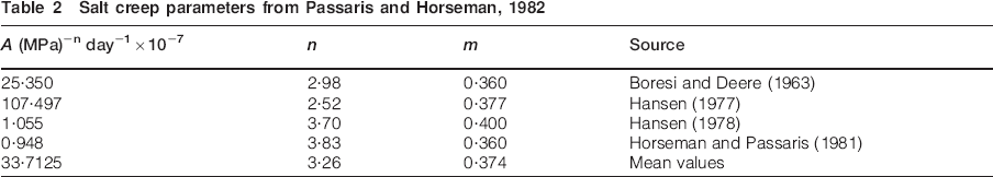
The values in Table 2 are suggested by the authors as a best estimate of the creep parameters that may be meaningful over the design life of a typical potash mine. A sensitivity analysis was carried on each set of parameters in Table 2 and this concluded that the mean creep parameter values stated would be a good starting point for generic design purposes. This was decided on the basis that relative to the mean values the worst case parameter set identified in Table 2 results in increased deformations by a factor of 1⋅6, whilst the best case parameter set results in deformations reduced by a factor of 26⋅4.
Isochronal analysis
For the isochronal analysis, each line on the graph represents a set point in time, in this case, between 1 and 75 years. This allows three parameters to be shown on two-dimensional graphs: time, pressure and creep deformation. Furthermore, as the cardinal axes are pressure and deformation, it is possible to superimpose shaft lining behaviour so that the compatibility and ultimately the design life, of any particular shaft lining, may be estimated.
The shaft lining behaviour can be calculated for a concrete shaft using the standard thick cylinder stress equations developed originally by Timoshenko (1976) and later re-arranged by Auld (1979).
Equation 5 (Williams and Auld, 2002) sets out the formula to determine the permissible lining pressure developed at the inside face of the shaft Pp, which is calculated based on a limit state design basis:
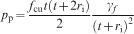
Subsequently, the corresponding lining deformation δl is derived from equation (5) (Williams and Auld, 2002)
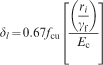
The point where the shaft lining stiffness intersects the isochronal curve defines the limit of creep deformation, as the lining resistance pressure will balance the residual adjacent ground pressures for that time curve (see Fig. 2). Consequently, the maximum value of creep deformation that will occur can be determined along with the corresponding maximum stress in the lining, allowing a safety factor relative to the lining failure stress to be calculated.
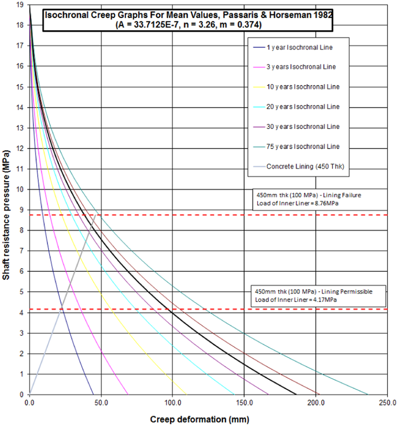
Typical isochronal creep deformation against shaft resistance pressure graph. Note in this example, the concrete lining can accommodate approximately 25 mm radial movement safely indicating approximately a 1 year design life. Similarly approximately 100 mm deformation capacity is required for a 40 year design life
Compressible fill material and results
An allowance for ground creep deformation at the back of the shaft lining may be made to accommodate the creep deformation and thereby extend the design life of the shaft structure. Whilst it would be possible to leave this annulus unfilled, it is preferable to include a compressible material to seal the face of the excavation and apply some resistance pressure to the creep deformation (see Fig. 3). Obviously, the resistance pressure must be less than the safe design pressure of the shaft lining. Historically, polyurethane foam has been used to fill the annulus, although this is currently not preferred, as will be discussed below. Recent projects have considered the use of foamed concrete as an alternative.
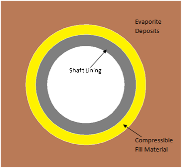
Typical plan view of the shaft and foamed concrete compressible material (not to scale)
Polyurethane
Historically, polyurethane has been used to accommodate ground creep deformation in mines in Saskatchewan, with the provision of an approximately 300 mm intermediate layer between the ground and the structural shaft lining. Recent observations of these mines indicate that the creep deformation rate is variable and uneven around the shaft. Inspections after 40 years show that in some parts of the shaft, the creep deformation allowance has been used up, while in other parts almost the full allowance remains. This may be a direct effect of the ground stress redistribution generated by station structures and other adjacent mine workings, as well as possible natural variability in the creep properties of the strata.
The placement of polyurethane in pre-expanded sheets or blocks is not a practical proposition during shaft construction, and consequently it must be foamed in situ. In an underground environment, this is less than ideal as the foam formation involves the evolution of a large volume of gas in an exothermic reaction. In the past this has led to instances of spontaneous combustion when placed in very large quantities typical of those required for shaft creep deformation applications.
The properties of expanded polyurethane foams may vary by a factor of about 10, even when considering similar densities. It is possible to obtain crushing pressures of up to 2 MPa, however, typical crushing pressures are much less than this. This makes specific foam testing and trial placement critical for the lining design if an accurate estimation of design life is to be achieved.
Whilst polyurethane is acceptable in terms of the creep deformation over the life of the mine, it is not preferred due to the flammable nature of the material.
Foamed concrete
Foamed concrete has been considered for use in recent Canadian potash mine development work. It is essentially air entrained concrete with a very high proportion of air. This material is especially preferred as it is non-flammable provided the concrete mix is designed specifically not to evolve hydrogen.
Similar to polyurethane, the foamed concrete is intended to slowly crush against the constant load of the creeping salt, thereby limiting the pressure transferred to the inner concrete lining. This increases the design life of the concrete shaft lining and reduces the maintenance required. It is conjectured that the cellular foamed nature of the foamed concrete prevents the voids within the material from being prematurely filled by crushed debris originating from higher up in the foamed concrete zone.
As this is a new application, some laboratory testing has been undertaken to confirm the confined deformation behaviour for the foamed concrete. These tests indicate a linear crushing pressure of around 1 MPa up to around 60% strain, before the crushing pressures rapidly ramp up to between 60 and 70% strain. On this basis, it can be assumed that approximately two-thirds of any deformation zone filled with foamed concrete, will be available to accommodate ground creep deformations, thus, 200 mm deformation capacity can be achieved from a 300 mm foamed concrete allowance.
The results from the laboratory sample testing have been plotted on the isochronal creep deformation graphs developed from the Passaris and Horseman, 1982 theory. This allows the compressible fill material to be considered in context with an expected shaft lining design life. While a factor of safety on stress can be developed, it is not particularly meaningful as the crushing resistances of the foamed concrete remain similar for all thicknesses. This means that there would be no increase in a stress based safety factor for the shaft when considering an increased deformation zone, e.g. a 1000 mm deformation zone has the same stress based safety factor as a 100 mm deformation zone, which is clearly unrepresentative of the relative risk of failure associated with these scenarios. This is considered unrealistic, consequently it is proposed to use a factor of safety based on time instead of stress. A time based safety factor can readily be derived from inspection of the isochronal creep deformation graphs (see Fig. 4).
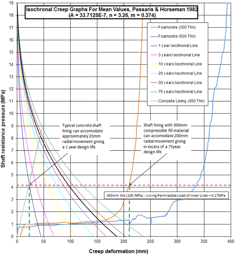
Typical isochronal creep deformation graph with compressible fill material information (note: 22⋅8 MPa field pressure, 5⋅5 m initial shaft excavation diameter)
Validation of analysis
In order to validate the creep predictions made for a shaft in any given rock salt it is important to collect monitoring data for the shaft pillar deformation. While extensometers could be installed from within the shaft, there are principally two main drawbacks to this approach. First, the saline environment is known to be very aggressive with respect to the longevity of electronic instrumentation required, and second the numbers of extensometers required for an array suitable for monitoring the salt section of the shaft would be very large. Consequently they could be reasonably used to monitor creep deformation in a few strata at discrete levels, but with the corrosion issues, their ability to retrieve long-term deformation data remains suspect.
A better solution would be to use inclinometers, however, this is normally problematic in deep mine shafts, as the crib foundation structures prevent the installation of inclinometers in the vicinity of the excavation when installed from the surface. However, it is thought to be possible to install inclinometers from the station level roadways and ventilation drifts adjacent to the shaft bottom structure to allow the absolute movement of the ground to be monitored, relative to the centreline of the shaft. This would allow the actual creep deformation to be recorded allowing for future improvements to the creep model and design life predictions.
What is less clear is how the casing for the inclinometer will perform through the creeping salt strata. Ultimately, readings can only be obtained whilst the casing remains sufficiently open to allow the travel of the inclinometer. It is considered impractical to install a casing capable of resisting the full geostatic pressure. However, given the size of the excavation required, it is hoped that the casing will prove sufficiently stiff to resist ovalling and buckling, thereby allowing the assessment of the overall creep deformations. At the very small excavation diameters required for the inclinometers, creep deformations of up to 5 mm are expected after 75 years.
Simple monitoring of the thickness of the deformation zone can be achieved using recessed rod extensometers as shown in Fig. 5. These have been recently installed in the concrete station lining of a Potash mine, and it is hoped that these will provide at least a crude validation of the creep model in the years to come.
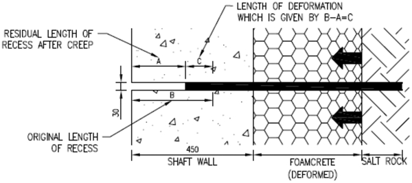
Recessed rod extensometer
Due to large variance in rock creep parameters, the exact thickness of foamed concrete appears to be less significant. The example shown in Fig. 4 demonstrates both 300 mm and 500 mm thicknesses and allow for the accommodation of the predicted creep based on the averaged creep parameter set, i.e. both 300 mm and 500 mm work for 75 years, see Fig. 4. However, until field validation of creep deformation is achieved, the authors recommend adopting the 500 mm foamed concrete compressible fill material, as this would also accommodate the 60% greater deformations associated with the worst set of creep parameters.
Conclusion
Subject to the satisfactory completion of field placement testing that is expected to corroborate the foamed concrete behaviour, suitably formulated foamed concrete is recommended for use as a compressible medium between the ground and the liner for a mine shaft.
Until field validation of the creep deformation model is achieved the authors recommend adopting a larger deformation zone whenever practicable. In the example case illustrated in this paper, the larger 500 mm foamed concrete compressible fill material would accommodate the 60% greater deformations associated with the worst set of creep parameters identified in Passaris and Horseman, 1982, although both the 300 and 500 mm zones are predicted to provide the required 75 year design life.
Note, as the use of foamed concrete as a compressible fill material is reliant on its controlled crushing, consideration must be given to displacement by gravity of the debris that will arise as the foamed material is crushed.
Footnotes
Acknowledgements
This paper was originally presented at the 3rd International Conference on Shaft Design and Construction organised by the Mining Technology Division of the Institute of Materials, Minerals and Mining, co-sponsored by the British Tunnelling Society, which took place on the 24 – 26th April 2012. The work was subsequently revised for publication in Mining Technology.