
Abstract
Pre-splitting is a controlled blasting technique with applications in open pit mines. The main objectives of pre-splitting in open pit mining are: preventing/controlling back-break; controlling excessive ground vibrations; and filtering the effects of explosive gases from production blasting. This technique is especially effective in back-break control through providing a separating surface between the main blasting pattern and open pit final walls. In this study, a large open pit mine was the case study for the goal of designing pre-splitting through implementation of direct and cost effective experiments. Three tests were designed and performed at the mine. Back-break was successfully controlled through proper design of pre-splitting based on the results of the experiments.
Introduction
The main objectives of pre-splitting in open pit mining operations are: preventing/controlling back-break; controlling excessive ground vibrations; and filtering the effects of explosive gases from production blasting. Pre-splitting in open pit mining is performed by arranging a row of blasting holes behind the main blast pattern (production holes). These holes will be blasted before or at the same time with production holes and separate the remaining rock mass from the blasting block (Calder and Tuomi, 1980). This artificially created free surface has been shown to be successful in controlling back-break (Singh et al., 2014). The separating surface attenuates propagation of expanding gases to the remaining rock mass i.e. the final walls (Adamson, 2013). In this method, a buffer row is placed in front of the pre-split to achieve better back-break control. Buffer holes are a row of lightly loaded blast holes in between the production and pre-split holes and are intended to adequately fragment the rock between the buffer row and the final wall without over-break (Workman and Calder, 1989). With regard to securing the desired fragmentation, the blast design is significantly important. However, it must be noted that the fragmentation, too, encounters problems because many factors are out of reach of the blast engineer hence solution seems to be difficult (Monjezi et al., 2009). Design of blast experiments is a method of defining optimal pattern of pre-splitting (Xu and Peng, 2008; Dai, 2005; Ozer et al., 2013). In this study, pre-splitting is tested in Golegohar iron ore complex, Iran. The rest of the paper is as follows: first, the case study is introduced and the results of three sets of pre-splitting experiments are discussed. Finally, the conclusion of the case study is summarised.
Case study
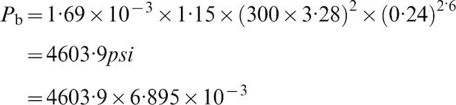
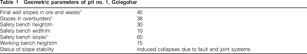
Golegohar iron ore mine is located in southern Iran, 50 km from Sirjan, in southwest of Kerman Province. This iron ore complex includes six known reserves and is one of the largest producers and exporters of iron concentrate in the country; it is mined by open pit mining. It has a measured and indicated reserve of over 1·1 billion tonnes of ore. The Golegohar deposits are situated in a metamorphic complex of probable Paleozoic age with a northwest-southeast trend, known as the Sanandaj–Sirjan zone, which is parallel to the Zagros thrust belt on the southwest, and is bounded on the northeast by the Urmieh–Dukhtar volcanic belt (Moxham and McKee, 1990). The deposits are considered to be of sedimentary or volcano-sedimentary origin, laid down in deltaic or near-shore locations that resulted in abrupt lateral and vertical changes in the sedimentary environment. Subsequent deep burial, folding, metamorphism, and erosion left a group of folded or down faulted magnetite rich deposits as elongated remnants of an iron formation that originally had a broader, perhaps more continuous extent. The mine's metamorphic rocks of Paleozoic consists mostly of gneiss, micaschist, amphibolite, quartzschist, marble, dolomite and calcite types of rocks (Karimi Nasab et al., 2011). Figure 1 illustrates one of the operating pits. Geometry and slope stability factors of the mine are summarised in Table 1. The hole pressure is an important parameter in controlled blasting that was calculated as below (Chiappetta, 2001)


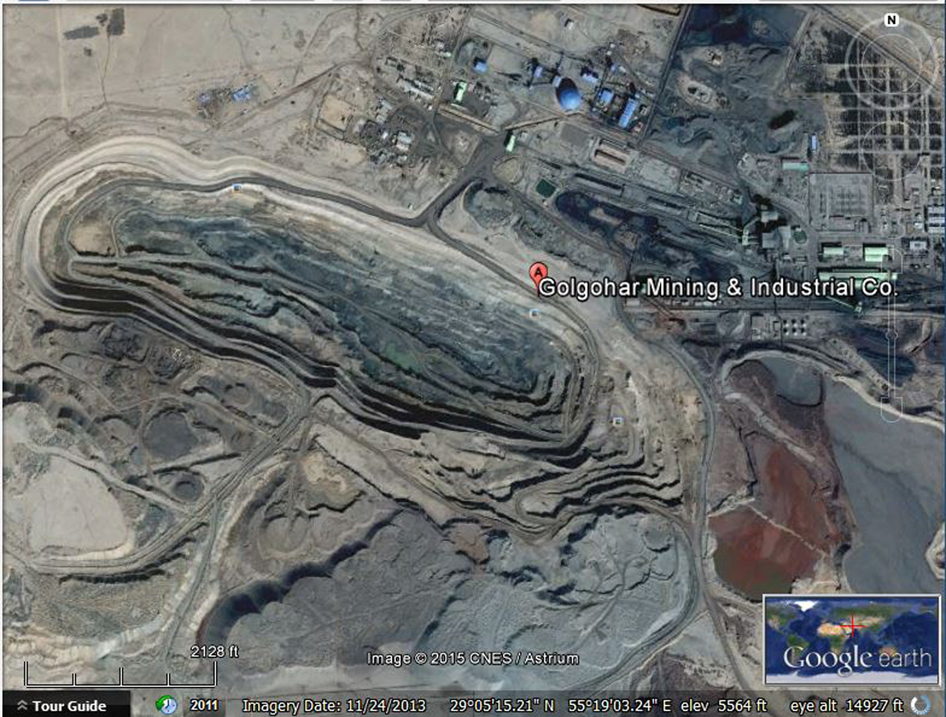
Open pit mining in Golegohar
Geometric parameters of pit no. 1, Golegohar
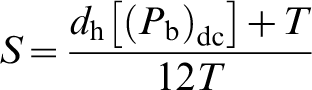
Equation (2) was used for calculation of presplit geometry
Rock mechanics tests
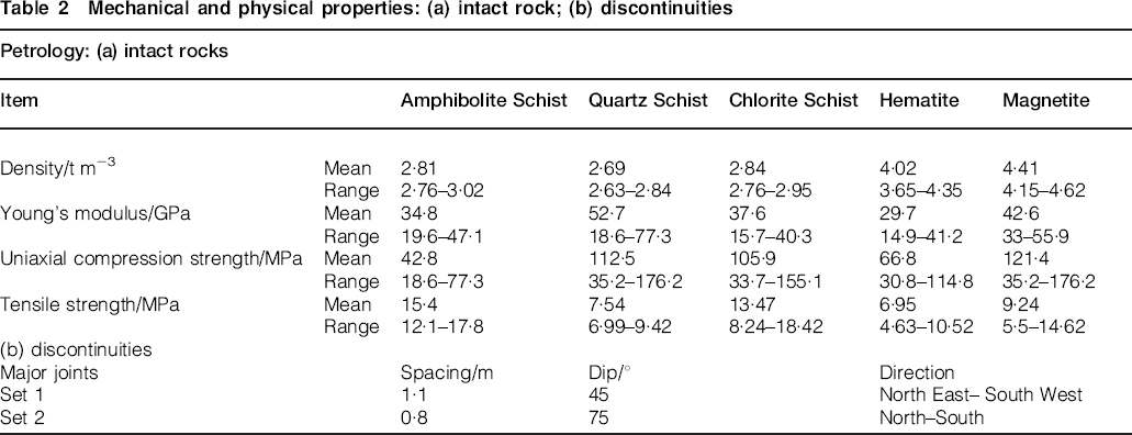
For pre-splitting studies with the objective of back-break control, rock mechanical properties tests were performed. Rock samples were collected and tested in the rock mechanic laboratory of the mine. Mechanical characteristics of rocks have been calculated as the mean value of 7-8 samples for each rock type (Table 2). Major joint sets characteristics are summarized in Table 2b.
Mechanical and physical properties: (a) intact rock; (b) discontinuities
Design of experiments
Test no. 1
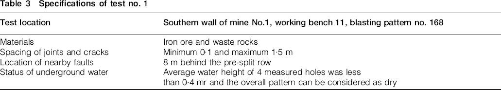
In this experiment, drilling and blasting operations were performed in two phases. First the pre-splitting row was drilled, charged, and blasted and then production and buffer holes were drilled, charged, and blasted. The specifications of this test are summarised in Table 3.
Specifications of test no. 1
Drilling, charging and stemming
Holes in pre-split row were drilled with 1·2 m spacing and with 70° inclination. The hole inclination is restricted by the mine's final walls slope as indicated in Table 1. The specified inclination for the last row has been identified through numerous blast practices in this mine. The spacing in the pre-split line has been decided primarily based on the results of similar mines in the area. The production holes were drilled vertically in a 3×4 m pattern. A line of buffer holes were drilled with 4 m spacing and 80° inclination with respect to the horizon. Pre-splitting holes were charged fully through plastic tubes with a diameter of 40 mm. Holes were fully charged with no stemming. Stemming length for production holes was 3·5–4 m and for buffer holes 2·5 m. The main charge was ANFO and hole diameter was 165 mm (Fig. 2).
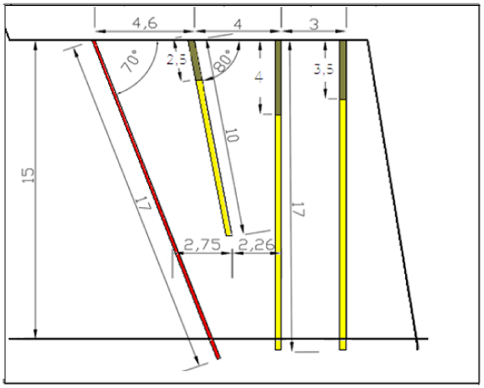
Blast patterns for test no. 1 (red: pre-splitting hole, yellow: ANFO, beige: stemming): distances are in metre and angles in degree
Results of test no. 1
Test no. 1 resulted in formation of a crack 2·5 m behind the pre-splitting row (Fig. 3). Since, pre-splitting is applied to form a separation surface only, but not rock fragmentation, it can be concluded that the blast power was too high. However, back-break might be due to the cratering and gas loading from the buffer hole and not the pre-split. The hypothesis of the excessive power of blasting has been tested here. In the calculated hole pressure the effects of faults, joint systems and other conditions such as the status of the boundary between ore and waste rock were not considered. By taking into account such conditions, the required blast power is reduced (Worsey, 1984).
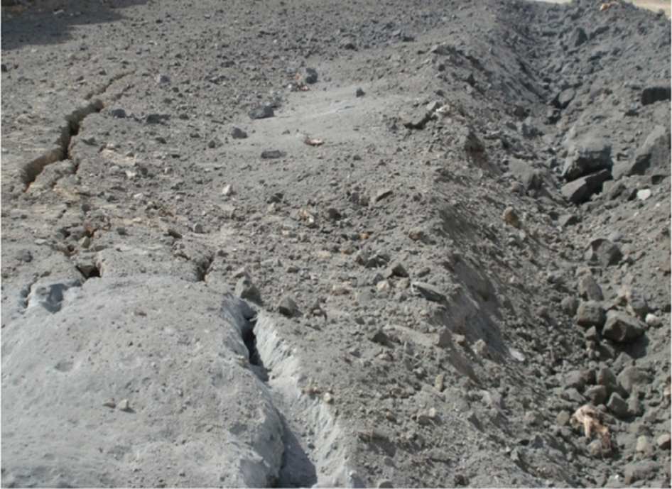
Test no. 1, crack propagated behind pre-splitting row
Test no. 2
To reduce the blasting power of the explosives used in a pre-splitting row, there are several alternatives. First, a reduction of the charge diameter, which was not applicable in this case, because the critical diameter of the blast powder is around 40 mm; second, ‘air decking’ (discrete charging through leaving empty intervals). This method is not applicable due to limitations in accessing required equipment as well as lack of previous experience with this method in the mine. Addition of salt to ANFO in specific ratio was proposed, which is a fast, easy, and considerably cost effective simple alternative. By reducing the strength of explosive in the last row, a considerable decrease in back break phenomenon can be achieved. Salt and sawdust are type of materials which can reduce the strength of Ammonium Nitrate Fuel Oil (ANFO). Some of the main advantages of using salt are: a remarkable reduction in back break, improvement of fragmentation and a reduction of explosive mass.12
Drilling, charging and stemming
In this test, salt and ANFO with a ratio of 0·3–0·7, i.e. 30 mass-% salt and 70 mass-% of ANFO were mixed. Three metres of the very bottom of pre-split holes were charged with pure ANFO and the remaining length of the holes with a mixture of 6 kg salt and 14·5 kg ANFO. This mixed charge with salt was applied only to the 12 holes which were closer to the fault. Furthermore, the upper first two metres of all pre-split holes were left empty (no charging or stemming was applied). Pattern specifications of this test are shown in Table 4.
Specifications of test no. 2
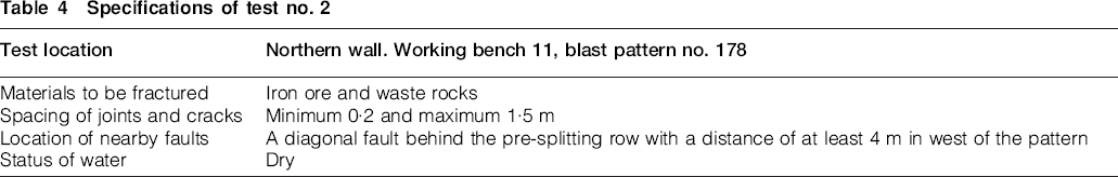
Production holes were drilled vertically and in a blasting pattern of 3×4 m, while the buffer holes were drilled with 80 degrees inclination and in a 4 m spacing (the same as test no. 1). Both production and buffer holes were charged with ANFO. These holes and their specifications are illustrated in Fig. 4.
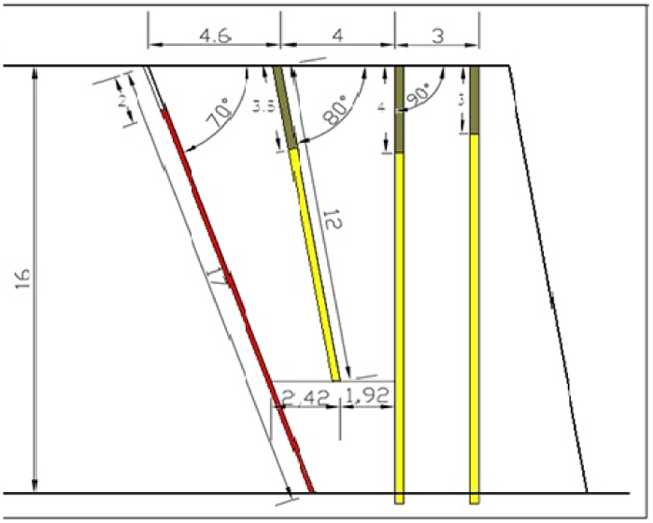
Blast pattern for test no. 2 (red: pre-splitting hole, yellow: ANFO, beige: stemming, white: no stemming/charging): distances are in metre and angles in degree
Results of test no. 2
In this case, back-brake is restricted to a smaller region (Fig. 5) but the final wall still suffers from excessive ore fragmentation (Fig. 6). To improve these areas, a third experiment was designed.
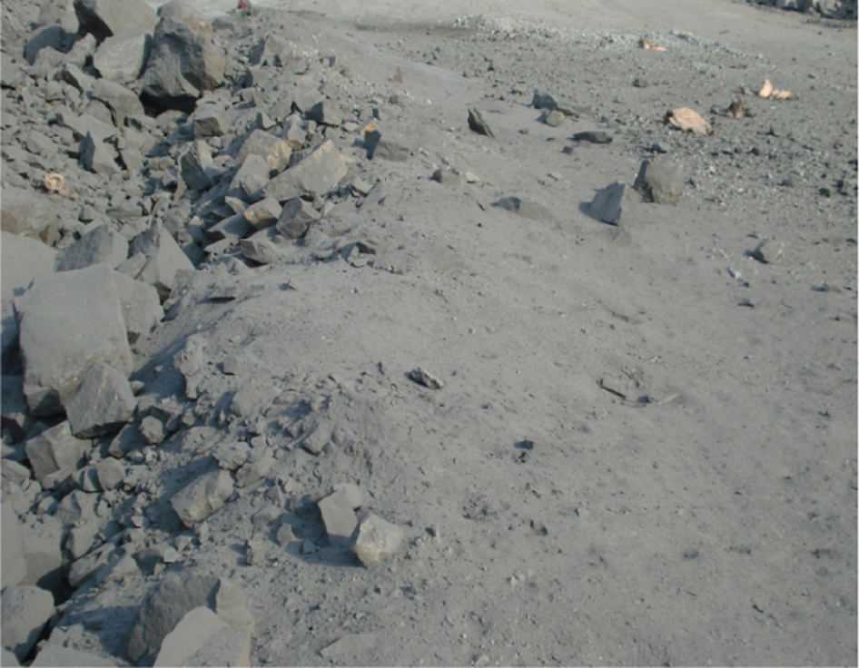
Pre-splitting blast without back-break behind pre-splitting row, test no. 2.
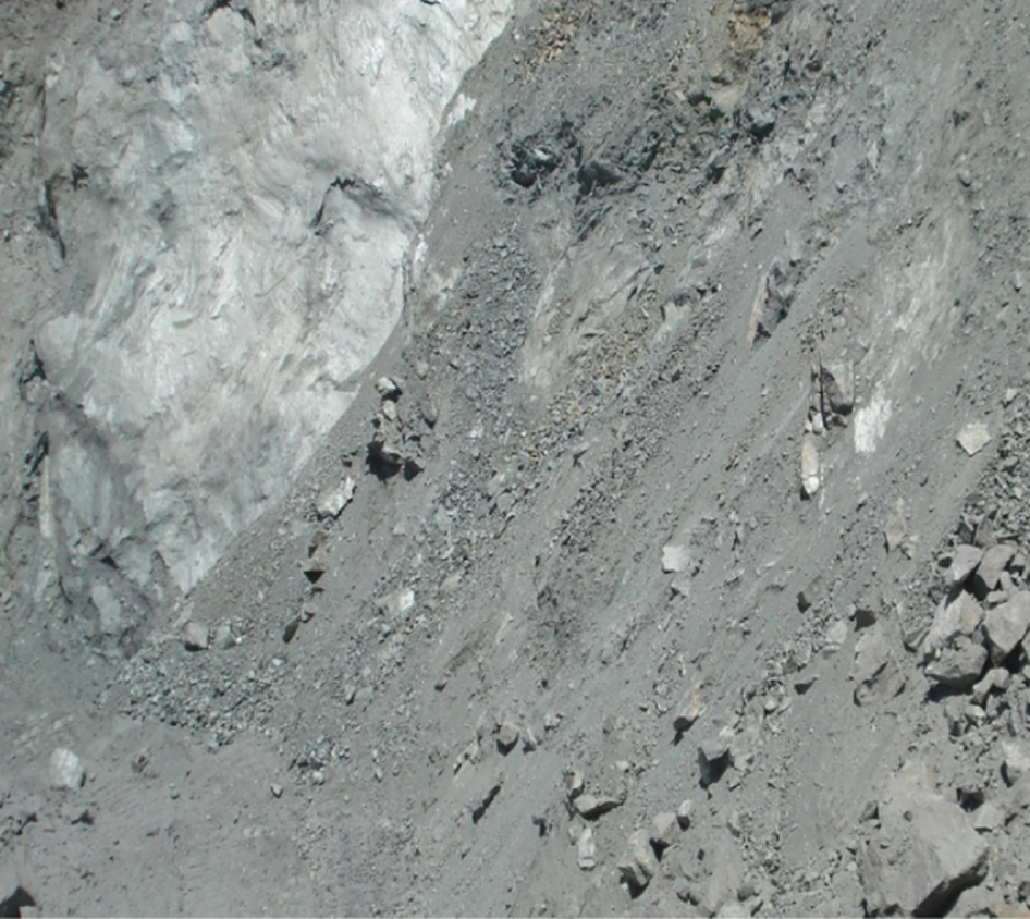
View of final wall after blasting
Test no. 3
Drilling, charging and stemming
Drilling and charging parameters of test no. 3 have been specified based on the results of previous tests of this study. Geometry of blasting patterns for pre-splitting, production, and buffer holes are 5·5×1·5, 3 and 4 m (spacing) respectively (Fig. 7).
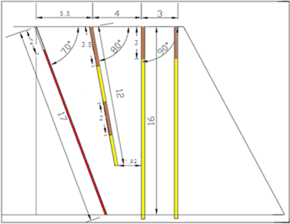
Blast pattern for test no. 3 (red: pre-splitting hole, yellow: ANFO, brown: stemming/crushed rock, white: no stemming/charging): distances are in metre and angles in degree
In this test, the buffer holes were charged discretely in a way that the very bottom 3·5 m of the holes were charged continuously, then 2 m of the hole was filled with crushed rocks, and then the explosives were charged (Table 5).
Pre-splitting design of test no. 3
Inspection and evaluation of test no. 3
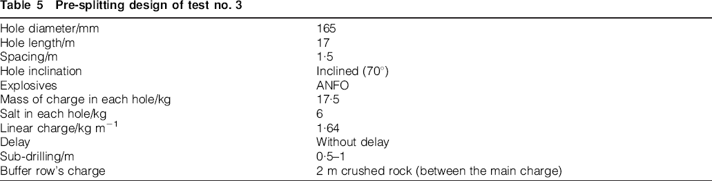
In the third experiment, charging method of buffer holes was modified (discrete charging). Also, spacing of pre-splitting holes increased to 1·5 m, as well as the distance from the last row of buffer holes, which was increased to 5·5 m. All other effective parameters were kept fixed. In this experiment, no back-break was observed (Fig. 8) and the shape and stability of final wall surface and slope were very satisfactory.
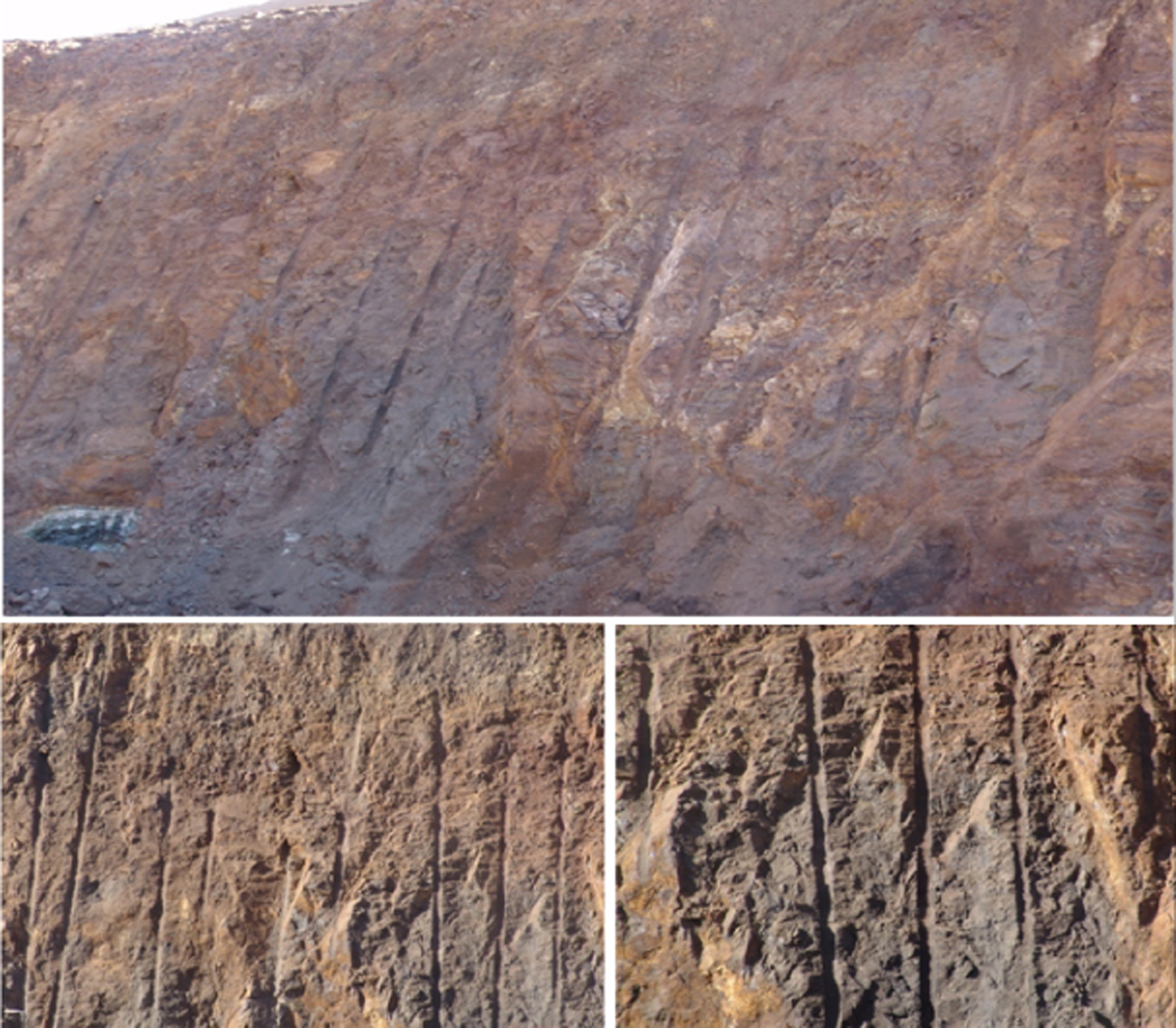
Final walls showing traces of holes of pre-splitting row after blasting
Conclusion
The main objective of pre-splitting blasting is to produce an artificial surface of separation between the blasted rock mass and the remaining rock mass on the final wall, which will lead to a smooth remaining wall without any/minimum back-break. In this study, three experiments were performed. Results of the first test were not satisfactory as the full length charging of the holes resulted in severe back-break.
In test no. 2, by mixing salt with the main charge (in a specific ratio) as well as leaving the top part of pre-splitting holes without charging or stemming, back-break was controlled, locally. In test no. 3, by increasing the spacing of the pre-splitting holes and partitioning the main charge in the buffer holes (power reduction), the perfect result was achieved (Fig. 8). In conclusion, in this case study we were able to obtain desired results from pre-splitting, experimentally and in a very cost effective way by:
adding salt, in a mass ratio of 0·3–0·7, to the main charge of the pre-splitting blast holes
leaving these holes without stemming
changing buffer holes charging method (discrete charging).