






Abstract
Periodic changes in the material properties of egg shaped profile filament wound fibreglass reinforced unsaturated polyester composite sewer liner pipes were investigated around the perimeter of the cross-section that has constant radii of curvatures in certain sections. On the basis of numerous test results and geometrical and mechanical models of the problem, linear relationships were set up between the origin of the specimens around the section and the density or fibre volume fraction of the material. The inverse proportion between the packing forces (perpendicular to the pipe wall) and the local radii of curvatures means that besides constant fibre tension, higher packing forces appear at the lower radii areas of the section, more matrix material is compressed out of the fibre bundles and the density or the fibre volume fraction becomes higher than in the higher radius areas.
Introduction
Polymer composites made of thermosetting polymer matrix (mainly epoxy, vinylester or unsaturated polyester resins) and reinforcing fibres (glass, carbon or aramide fibres) show high strength, acceptable elastic modulus, low density and high chemical resistance. These special properties have made fibre reinforced polymer composites suitable for the underground piping industry, where the low maintenance need of these materials is an additional benefit.1 Glass fibre reinforced unsaturated polyester pipes and vessels have been manufactured for more than four decades and applied successfully in chemical and food industries and in underground water and sewerage piping.2 Major advantages of polymer composite pipes compared to steel ones are low weight, which decreases construction and transportation costs, and corrosion and chemical resistance, which reduces maintenance costs and lengthens the lifetime of the pipes. Compared to thermoplastic polymer pipes (polyethylene, polypropylene and polyvinyl chloride), composite pipes have higher strength, which gives higher pressure resistance and load bearing capacity3 and finally allows the designer to use lower wall thicknesses. Besides their advantageous special properties, polymer composites often show uncommon behaviours, such as time and temperature dependent properties,4–6 degradation7 and water absorption,8 owing to the macromolecular structure of the polymer matrix material. Composites also show uncommon damage modes in comparison with homogeneous materials, such as interlaminar fracture types, 9 , 10 owing to their fibre reinforced laminated structure.
Composite pipes are manufactured mainly by filament winding and centrifugal spraying, and they can be operated under gravity or as pressure pipes. The filament winding manufacturing technology is more common for high performance pipes mainly because the anisotropic mechanical properties of the pipe material can be fitted to the loads by changing the winding angle. 11 , 12 It is also more capable of manufacturing non-circular profile pipes, because a wooden mandrel with non-conventional geometry can be fabricated economically even for smaller series of production.
In the early stage of sewerage piping, various cross-sections were used for pipe construction from stones or bricks with masonry technique.13 The so called regular egg shaped (or normal ovoid) profile was one of the most widespread non-circular cross-sections from the end of the eighteenth century because of its good flow and ergonomic properties14 (Fig. 1). The first egg shaped sewers were constructed in London in 1846, and later, in the 1870s, they were also used in Germany. Up to now, one can find hundreds of kilometres of egg shaped sewers in the main cities of Europe, such as London, Paris, Brussels, Berlin, Dresden, Hamburg, Vienna, Budapest, etc. In the case of a combined (communal wastewater and rainwater) sewer, the egg shape profile provides deeper flow during dry periods, owing to the narrow lower part of the section, than an equivalent circular profile, and this way, it prevents sedimentation. In case of wet weather, the section has enough spare capacity to transport stormwater. On the other hand, egg shape is very similar to the figure of the human body (e.g. on all fours); this is why a 1200×700 mm section or even smaller can be man accessible. An egg shaped profile is ‘anatomic’ because of the vertical alignment and the wider crown region that lets shoulders in the sewers. An additional benefit of egg shaped sewers was, during the construction works, that a narrower trench was suitable for laying them than the one for an equivalent circular pipe (with equal cross-sectional area). Nowadays, egg shaped profile pipes are mainly used for the repair and recovery of deteriorated pipelines, because manufacturing various non-circular profiles for new construction is not cost effective enough, and sizes cannot be easily standardised.

Regular egg shaped profile, α1 = 180°, α2 = 36·87° and α3 = 53·13° (1: resin impregnated fibreglass filaments, wound under +θ angle; 2: resin impregnated fibreglass filaments, wound under −θ angle)
A notable amount of the non-circular profile pipes are older than a hundred years and need to be rehabilitated in order to provide safe and environmentally friendly operation. Effective ways of repairing underground pipes are the trenchless lining technologies, since the surface traffic is only slightly affected by the construction works. One of the most common trenchless sewer pipe lining technologies is ‘cured in place pipe’ lining,15 where a preformed reinforcement hose preimpregnated or wetted in situ by uncured resin is pulled into the section to be repaired and then filled and cured with pressurised steam. Another well known relining technology is the ‘short pipe process’, where prefabricated (cured) liner pipe sections are pulled or pushed (jacked) into the old deteriorated pipe. Both technologies are capable of lining non-circular profile pipes. Liner pipes for the short pipe process are mainly manufactured with filament winding of the fibreglass reinforced polyester. In the case of filament winding of non-circular pipes, owing to the uneven forces acting on the fibre filaments around the perimeter of the winding mandrel, varying wall thicknesses can occur.
The aims of this study were to analyse the wall thickness and material property variations observed during the filament winding of egg shaped profile composite pipes and finally to find the reasons for these variations. This is important because the wall thickness and material properties of the pipe material are crucial input parameters of every modelling, scaling and stress analysing method, such as finite element modelling.
Experimental
Material and manufacturing technology
The tested pipes were manufactured from fibreglass reinforced polyester, which is a very common material in composite piping because it has good mechanical properties, excellent chemical resistance and low prize. The fibrous reinforcing material provides the strength and stiffness to the composite, and the impact resistant matrix material protects the fibres and helps load transmission between the fibres. The matrix material of the examined composite pipes was an AOC Altek H577-AEF-30 type orthophthalic acid based unsaturated polyester laminating resin. The applied reinforcing material was a Johns Manville Star Rov PR 300 2400 907 type direct glass roving made with a linear density of 2400 tex. The roving was manufactured with silane sizing, which provides excellent adhesion to unsaturated polyester.
The pipes were manufactured with filament winding technology at Hodács Composites Ltd (Hungary). Dry fibreglass rovings were wound on an egg shaped profile wooden mandrel under 83·5° to the longitudinal axis of the pipes and impregnated manually after each layer. The composite material was cured at room temperature and post-cured at 80°C for 1 h. The test pipes were manufactured with the same winding programme of four layers in the following order:
 (where the f index refers to the ‘quasi-fabric’ structure of the filament wound pipe wall), and the nominal wall thickness was 2·4 mm. The wall thicknesses of the test pipes varied around their perimeters owing to the non-circular profile. In the following paragraphs, the nature and the reasons of variations in material properties (density and fibre volume fraction) around the profile will be analysed.
Geometry
The examined filament wound sewer lining pipes were made with a regular egg shaped profile (Fig. 1), which consists of three arcs connected with common tangents. The nominal cross-sectional dimensions of the tested pipes were as follows: a = 160 mm, b = 240 mm and R = 80 mm. The length of the examined pipes was 1 m.
Test methods
Three pipes were tested to check the reproducibility of the manufacturing technology and the variations in density and fibre volume fraction around the perimeter of the section. Specimens were taken from each end of the three test pipes. First rings were cut from the ends of the pipes (altogether six rings), and then square (20×20 mm) pieces were cut from particular areas of the rings. Five pieces from the upper, four pieces from each lateral and three pieces from the lower regions of the rings were taken, as can be seen in Fig. 2. Altogether, 96 square specimens were fabricated, in which the tests were executed. The pipe ends were numbered and referred as ‘end 1’ and ‘end 2’ in the tables.
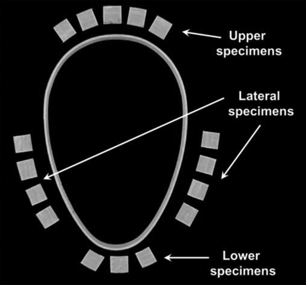
Ring and square specimens cut from test pipes
The density of the composite material was examined according to ISO 1183-1 using the immersion method. The fibreglass weight fraction was determined with the burning method according to ISO 3451-1. As the density of reinforcement fibres is almost two times higher than that of the matrix material, the fibre content was calculated into volume fraction with the help of equation (1) to give more proper information about the material composition

Results and discussion
Table 1 shows the results of the executed density measurements. Each cell contains the average and standard deviation values of the examined specimen series. The average and standard deviation values were calculated for the same type series under the relevant rows using all the raw data obtained during the tests to show the differences between specific regions of the test pipes.
Density values measured on specimens taken from different parts of examined pipes (pipe 1 end 1 refers to first end of pipe 1)
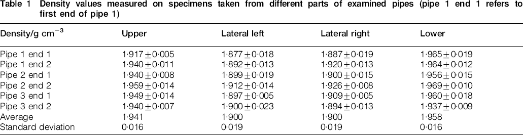
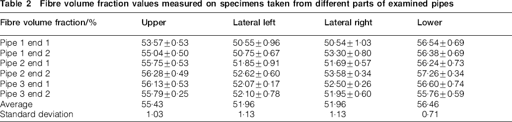
Table 2 shows the determined fibre volume fractions of the test pipes in the same order as in Table 1. Analysing the results, it is obvious that both density and fibre volume fraction are the highest in the lower region of the section (smallest local radius of curvature) and the lowest in the lateral regions (biggest local radius of curvature). The differences between the values are quite small, but concerning the very low deviations (under 2%), it is worth analysing the data statistically. Student t tests were applied to verify if the small differences are significant or are due to the accidental scattering of results. q (%) values in Table 3 show the probability of invalidity of the hypothesis that the pairs of data series are scattering around the same average values. Student t test results show that the differences between the average values of densities and the fibre volume fractions of the pipe material in different regions are significant. After analysing the validity of the results, the graphs in Fig. 3 were constructed showing the examined properties as a function of the radii of curvatures of the place of origin of the specimen series.

a density and b fibre volume fraction of egg shaped profile composite pipes as function of local radius of curvature of profile
Fibre volume fraction values measured on specimens taken from different parts of examined pipes
Student t test results for densities and fibre volume fractions measured on specimens taken from different regions of test pipes

The strong linear relationships in Fig. 3 can be written with the help of equations (2) and (3)


Figure 4 shows the universal geometrical and mechanical models of the filament winding process in case of a cylindrical mandrel. The fibre bundles are placed on the cylindrical mandrel under helical alignment so that they include the θ angle (winding angle) with the axis of rotation. Tensile forces F and F+dF act at the ends of a small line element ds of the helix in the tangential directions, perpendicular to the constant radius of curvature Rg in the endpoints owing to the fibre fastening system of the winding machine. Resultant force coming from the tensile forces acting on the selected line element with dβ central angle (estimated with straight section in case of small angle) is the so called packing force dN, which acts in the direction of the centre of curvature of the winding mandrel. Assuming that the difference between the tensile forces acting on the ends of ds is only caused by friction, equation (4) can be written on the basis of the simple formula for rope friction forces


a geometrical and b mechanical model of filament winding of circular profile pipe
As fibres are impregnated with liquid resin during filament winding, ‘lubricated’ friction occurs instead of dry friction, as originally assumed in equation (4). This effect lowered the friction forces between the fibres and the winding mandrel significantly, so the effect of friction was neglected. Considering that dF = 0, equations (5) and (6) can be written using proper triangles of Fig. 4b


Conclusions
According to the presented geometrical and mechanical models and calculations, the following conclusions can be drawn.
During the filament winding of egg shaped profile composite pipes, the applied constant fibre fastening forces resulted in higher packing forces (perpendicular to the surface of the winding mandrel) in the smaller radius regions (lower and upper part of the profile) and caused lower normal forces in the higher radius lateral regions.
Lower packing forces compressed a smaller amount of spare resin out of the fibre bundles, and this way, the density and the fibre volume fraction became lower in the lateral regions and higher in the lower and upper regions of the profile.
Higher wall thickness of the tested pipes in the lateral regions is caused by extra resin that could not be compressed out of the continuous fibre bundles owing to the lower packing forces than in the lower and upper regions.
One of the observed special behaviours of filament wound non-circular composite pipes was described by applying geometrical and mechanical considerations. The results of this study can be applied in the stress modelling and calculations of non-circular composite pipes to make the design procedure more accurate. For example, a simple linear function can be defined in order to describe the density or fibre volume fraction of the composite material along the perimeter of the modelled pipe, and a more realistic model can be created this way.
Footnotes
Acknowledgements
Publication of results was supported by the Hungarian Ministry of Economics through grant no. GVOP-2004-3·1·1. This work is connected to the scientific programme of the ‘Development of quality-oriented and harmonized R+D+I strategy and functional model at BME’ project. This project is supported by the New Hungary Development Plan (project no. TÁMOP-4·2·1/B-09/1/KMR-2010-0002). The authors say thanks to Hodács Composites Ltd for manufacturing the test pipes.
This paper is part of a special issue on Latest developments in research on composite materials