
Abstract
Earlier work has shown that a fracture mechanics approach can predict fatigue failure in rubber or elastomer components using a finite element analysis technique that calculates the strain energy release rate for cracks introduced into bonded rubber components. This paper extends this previous work to examine real fatigue measurements made at both room temperature and 70±1°C in both tension and shear using a cylindrical rubber to metal bonded component. This component generated fatigue failures not only in the bulk of the component but also at the rubber to metal bond interface. The fatigue crack growth characteristics were measured independently using a pure shear crack test piece. Using this independent crack growth data and an accurate estimate for the initial flaw size allowed the fatigue life to be calculated. This fracture mechanics approach predicted the crack growth rates well at both room temperature and 70±1°C.
Introduction
The stress versus the number of cycles to failure approach, which has been adopted widely1 to determine fatigue life of engineering components, has also historically been used2 in the elastomer component industry. An alternative approach to predict the fatigue life of elastomer testpieces utilises fracture mechanics.3 Lake4 reviewed the fracture mechanics approach, whereby a crack under a particular loading configuration will have a strain energy release rate which will for a particular rubber correspond to a specific crack growth rate. The strain energy release rate, which is a measure of the energy required to create a unit area of new crack surface, is also referred to in the literature as the tearing energy T, as well as the toughness

Figure 1 shows a typical double logarithmic plot of the crack growth rate per cycle (dc/dn) against the strain energy release rate T for a filled natural rubber (NR) elastomer. Lake14 and Lake and Thomas15 discuss the crack growth behaviour of rubber in the different regions. In this work, the crack growth behaviour of interest is described by region III which can easily described using a power law relationship


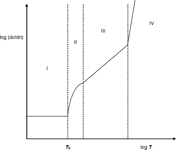
Typical double logarithmic plot of crack growth rate per cycle (dc/dn) against stored energy release rate T for filled NR elastomer: different regions highlight different types of tear behaviour
Experimental
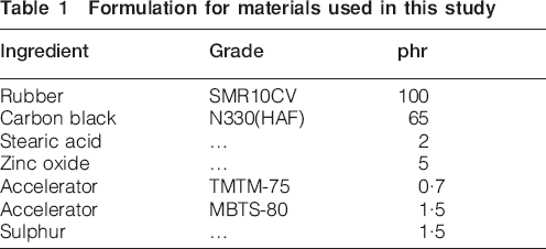
The material used for this work was a commercially formulated 65 phr HAF 330 carbon black filled NR compound supplied by Trelleborg AVS (Sjöbo, Sweden). The rubber formulation is given in Table 1. The rubber materials were supplied as rubber sheets of ∼2 mm thickness, from which pure shear samples of 175 mm width (w), 25 mm height (l0≈14 mm) and 2 mm thickness (t), were prepared as well as dumbbell testpieces using an ASTM D412 type C dumbbell die. In addition, simple bonded suspension mounts were injection moulded out of the same compound. Figure 2 shows a typical cylindrical bonded suspension component examined in this study. It has dimensions of 42 mm in height (including the bonded metal end plates) and a diameter of ∼47·5 mm. The two metal end plates were each ∼2 mm in thickness. Figure 3 shows a schematic for the pure shear crack growth rate test specimen used to characterise the cyclic crack growth rate versus tearing energy behaviour.
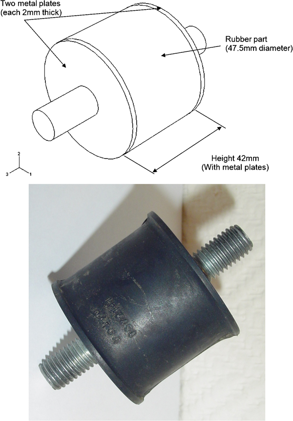
Cylindrical component used in this work
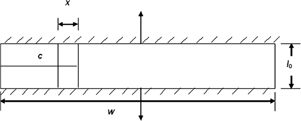
Schematic of pure shear crack growth test specimen
Formulation for materials used in this study
To determine the stress versus strain behaviour of the elastomer material, white marks were inserted on the reduced width section of the dumbbell specimen, equidistant from the centre and perpendicular to the longitudinal axis. The specimen was marked ungripped. The tensile test was carried out using an Instron 5567 universal test machine equipped with 1 kN load cell to measure the force and an optical extensometer to measure the displacement (strain) of the two white marks painted onto the surface of the testpiece. The tensile test was carried out at a strain rate of 50 mm min−1 for the room temperature (23±2°C) characterisation. The stress versus strain behaviour at 70±1°C was performed in an oven, which prevented the use of optical extensometer. Therefore, in this case the load was applied in a stepwise manner and the displacement was measured using a travelling microscope through a glass window in the oven. Figure 4 shows the virgin stress versus strain behaviour for the material at both temperatures.
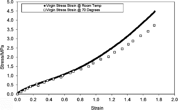
Stress strain behaviour for virgin dumbbell specimen in tension at room temperature and 70°C
The stress strain behaviour was also measured on dumbbell testpieces that had been cyclically stress softened for 999 cycles at an appropriate prestrain at both room temperature and 70±1°C. The one-thousandth cycle stress strain behaviour was used in the FEA to calculate the tearing energies associated with crack growth in the elastomer component. The one-thousandth cycle stress strain behaviour was used to account for the cyclic stress relaxation. Davies et al.16 and more recently Asare et al.17 have developed a strategy to correctly characterise the amount of cyclic stress softening present in a rubber component which depends upon the amount of the maximum average strain encountered in the testpiece. That is a materials characterisation on a testpiece that can be used to predict the behaviour in a component. To adopt this approach in this work, it was necessary to estimate the average strain in the elastomer component when stretched to the maximum cyclic displacement for a specific test. This then allows the specific maximum extension ratio at which to soften the testpiece for stress strain characterisation to be determined. Therefore, the appropriate strain to cycle the dumbbell test specimen is ∼90% to characterise the stress softening that is encountered in the cylindrical components when stretched in tension to a maximum displacement of 30 mm. This approach ensured that the softening in the elastomer component under cyclic loading is accounted for in the testpiece stress strain characterisation rather than neglecting it as has been the practice in previous studies.
To characterise the fatigue crack growth behaviour, the pure shear testpieces were gripped along their long edges with a crack introduced as shown in Fig. 3 and fatigue tested with an Instron 8872 servohydraulic test machine equipped with a 25 kN load cell. The wave form of the test was sinusoidal with a frequency of 1 Hz. All testpieces had an initial razor cut of 30 mm inserted into them. Papadopoulos et al.18 have highlighted the risks of assuming that the initial crack growth behaviour from a razor cut is typical after the crack tip has roughened up. As a result, all the crack growth measurements were made after the initial razor induced high crack growth rate had reached a steady state condition. Crack lengths were measured at the corresponding number of cycles for tests at different displacement amplitudes. Plots of crack length against the number of cycles were then made to calculate the crack growth rate for specific displacement amplitudes. The fatigue crack growth behaviour was characterised at both room temperature (23±2°C) and 70±1°C in an oven.
Busfield et al.19 showed that for a pure shear testpiece (Fig. 3) with unstrained height l0, thickness t, width w and a crack of size c, the tearing energy T can be calculated using equation (6) below

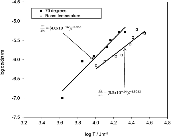
log dc/dn against log T from pure shear characterisation of NR65 material at room temperature and 70°C
The force deflection behaviour of the cylindrical component was measured at room temperature (23±2°C) and 70±1°C (in an oven) using an Instron 8872 servohydraulic test machine run in a static mode and at a strain rate of 50 mm min−1. The one-thousandth cycle force deflection behaviour (after cycling the component for 999 cycles at a maximum tensile displacement of 30 mm) was measured at room temperature and 70±1°C for the cylindrical component. The cylindrical component was also tested at different amplitudes and at a frequency of 1 Hz at room temperature and 70±1°C to determine the experimental number of cycles required to initiate and grow cracks to a measurable size. A sinusoidal wave form was used in all the tests. No initial razor cuts were inserted into the cylindrical component and the experiment was conducted under fully relaxing conditions. The fatigue tests were conducted in tension and shear deformation modes. The number of cycles required to initiate and grow cracks at the rubber/metal bond interface to a measurable size was recorded and the average crack length was measured using a Vernier calliper as a probe.
Finite element analysis
Finite element modelling has been used widely in the past to predict the stiffness of simple rubber components by, for example, Busfield and co-workers.9, 20 Here the method was initially used, to validate the model, to predict the stiffness of the cylindrical component using the approach suggested by Suphadon and Busfield.21 This model also gives a good indication of any likely crack initiation sites. Subsequent models were used to calculate the tearing energies associated with cracks growing in specific locations in the component. The technique requires the definition of: the component geometry with a suitable finite element mesh; the material behaviour; the boundary conditions and the loading conditions. In this work, Abaqus (version 6·6–1) was used to model the component and display the results. The filled rubber in the model was described using a hyperelastic Yeoh22 strain energy function as described by Liang et al.12 The coefficients were derived from experimental stress strain data measured as described previously.
The energy balance technique was used to calculating the tearing energy associated with specific cracks being found in the component. This and other methods for calculating the tearing energy associated with crack growth in elastomer testpieces and components were evaluated by Busfield et al.9, 23 With this approach, the difference in the magnitude of the total internal strain energy dU is calculated between two models held at a fixed displacement where the crack tip area A is extended by a small area dA. The tearing energy is equal to dU/dA. This technique is also known as the node release or the virtual crack extension technique.
The component was unless otherwise specified modelled using eight-node linear brick, hybrid, constant pressure elements C3D8H. The first model was used to predict the force deflection behaviour in tension and to give an indication of regions of potential fatigue failure under tensile loading. The bottom surface nodes of the component were fully constrained and the top nodes were all translated in the z direction. All top surface rotational degrees of freedom were constrained. All translational and rotational degrees of freedom of the bottom surface were constrained. The summation of all the reaction forces of the top surface nodes was recorded at different displacements to determine the component stiffness. The strain energy density distribution was also observed to indicate the regions of potential failure. Figures 6 and 7 show the displaced geometry under the tensile and shear loading respectively.
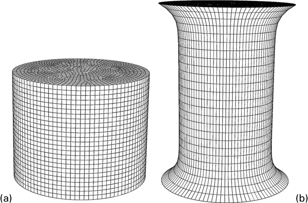
a meshed undeformed cylindrical component and b meshed cylindrical component deformed in tension
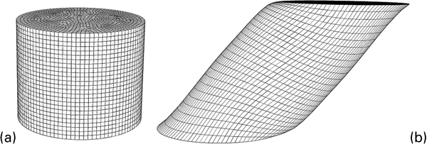
a meshed undeformed cylindrical component and b meshed cylindrical component deformed in simple shear
The crack growth was also modelled using finite element techniques. In tension it was apparent from the strain energy distributions observed in the crack free models that the parts would fail at the bond interface between the rubber and the metal plates as reflected in the actual fatigue behaviour. Owing to the symmetric nature of the component and the crack growth profile when loaded in tension, an axisymmetric model was developed to calculate the change in strain energy in the component with crack growth. The model was meshed with CAX4H axisymmetric elements. Figure 8a shows a meshed and undeformed axisymmetric model of the component. To account for small changes in the strain energy due to initial growth of defects (flaws) at the rubber–metal bond edge, the model was meshed with a high mesh density of 0·2 mm for the first part of the crack growth. The crack growth was modelled by releasing nodes at the rubber/metal bond interface. The virtual crack extension technique was used to calculate the tearing energy associated with crack growth along the rubber/metal bond interface. Figure 8b shows a meshed and deformed axisymmetric model of the cylindrical component in tension.
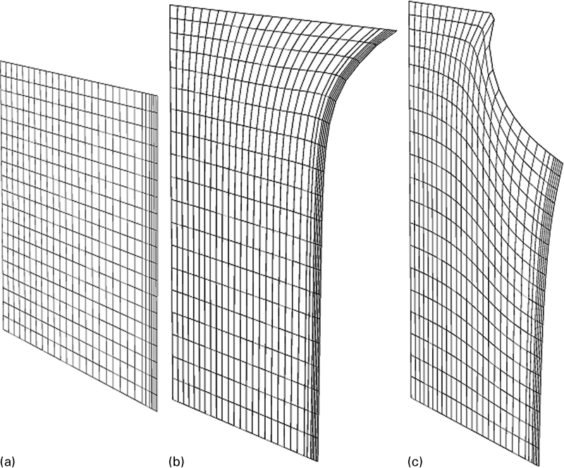
a undeformed axisymmetric mesh, b tension deformed axisymmetric mesh and c tension deformed axisymmetric mesh with crack
To model the component's fatigue crack growth in shearing a half symmetry three-dimensional model was used exploiting the symmetry found in the cylindrical component and the crack growth profile. Figure 9a presents a meshed and undeformed half symmetry model of the component. To account for small changes in the strain energy due to growth of defects (flaws) at the rubber–metal bond edge, the model was meshed with a mesh size of 0·2 mm for the first 1 mm of crack growth. The virtual crack extension technique was used to calculate the tearing energy associated with crack growth along the rubber/metal bond interface. Figure 9c presents a meshed and deformed half symmetry model of the cylindrical component in shear containing two cracks.
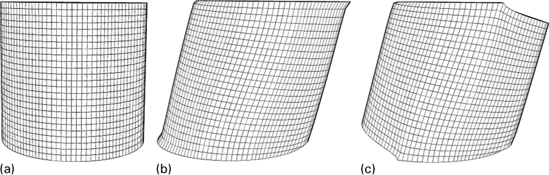
a undeformed half symmetry mesh, b simple shear deformed half symmetry mesh and c simple shear deformed half symmetry mesh with cracks
Results and discussion
Figure 10 compares the measured of the one-thousandth cycle force deflection behaviour at room temperature to the corresponding FEA prediction for the cylindrical component using the one-thousandth cycle stress strain data. The force deflection behaviour of the component is well predicted up to a maximum displacement of 25 mm after which the FEA model overestimates the force deflection behaviour. The modest discrepancy in the force deflection prediction after 25 mm maximum displacement can be attributed to the difference in maximum average strain energy density in the testpiece and the component during the stress softening. Also it is difficult to ensure identical cross-link densities in the compression moulded flat sheets and the injection moulded components studied in this work. This was checked using experiments that measure the equilibrium swelling in n-decane on the two samples. A cross-link density of 1·452×10−4 mol cm−3 was measured for the flat elastomer sheet material and a slightly higher value of 1·609×10−4 mol cm−3 was measured for the component material. It is evident from Fig. 10 that the average strain energy density approach for accounting for the cyclic stress relaxation in the strain energy calculations gives good results over a sufficiently wide range of displacement to be considered reliable for this work.
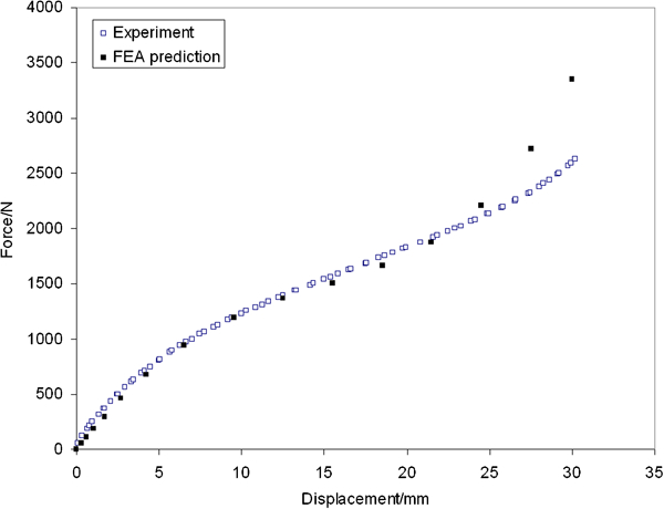
Experimental one-thousandth cycle force deflection behaviour and FEA prediction (using one-thousandth cycle dumbbell specimen stress strain data) of one-thousandth cycle force deflection behaviour of cylindrical component at room temperature
Figure 5 shows the crack growth characterisation results for the filled NR material. The slope determines Ψ to be 1·80 at room temperature and 2·37 at 70°C. As expected the filled NR material is weaker at elevated temperatures as less energy is required to grow a crack at a similar rate at 70°C. In practice components usually operate above the ambient temperature as a result of hysteresis. The need therefore arises to predict the fatigue life of components at elevated temperatures. A rise in temperature reduces the fatigue crack resistance and therefore reduces the components fatigue life. As expected the stiffness was also seen to be reduced by an increase in temperature.
The methodology for predicting the fatigue life is illustrated in Figs. 11–13. Figure 11 shows the relationship between the FEA calculated total strain energy in the model versus crack length for a crack grown in tension in the cylindrical component at room temperature for different displacement amplitudes. By using equation (1), it is seen that the gradient along the curves of Fig. 11 gives the tearing energy relationship described by equation (3). This new relationship is plotted in Fig. 12, which shows that the tearing energy of the cracks at all the different amplitudes increases as the crack grows at the rubber/metal interface. Substituting this value for the tearing energy into equation (2) fitted to the data shown in Fig. 5 gives dc/dn given by equation (4). This relationship can be inverted as 1/(dc/dn) as shown in equation (5). Figure 13 shows 1/(dc/dn) versus crack length for crack growth in the cylindrical component in tension at 5 mm amplitude at room temperature. Integrating under the 1/(dc/dn) versus crack length curve from an initial crack size c0 to a final crack size c gives the number of cycles required to grow a crack from c0 to c (crack range c0–c) and hence the fatigue life if c is large enough to cause a catastrophic failure. The method above was carried out for fatigue life prediction in tension and shear at room temperature as well as 70±1°C. Figure 14 shows the tearing energy crack length relation of the component in shear and at room temperature. Unlike that in tension, the tearing energy increases at the beginning of the crack growth and then passes through a maximum. This trend can be attributed to the geometry of the component studied in this work. Using the method discussed above, the numbers of cycles required to grow cracks at the rubber–metal bond edge of the elastomer component in tension and shear at both room temperature and 70±1°C were calculated as Np and compared with the experimentally measured number of fatigue cycles Nm in Table 2.
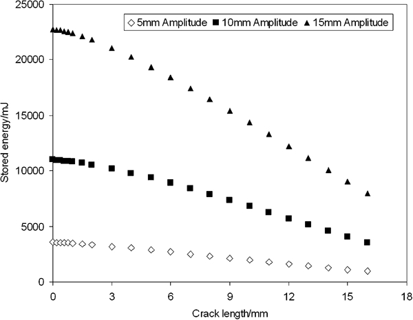
Stored energy against crack length for crack growing in cylindrical component under tension at 5, 10 and 15 mm peak displacement amplitude at room temperature
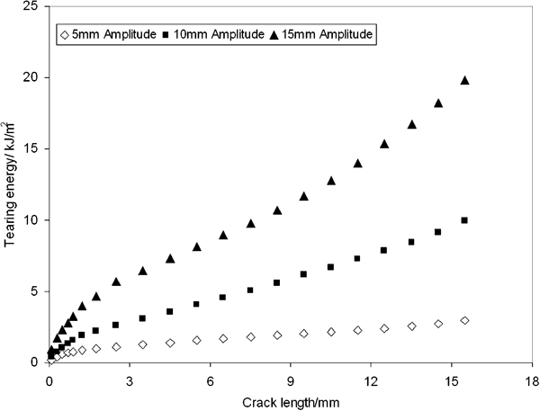
Tearing energy crack length relationship for crack growth in cylindrical component in tension at 5, 10 and 15 mm peak displacement amplitudes at room temperature
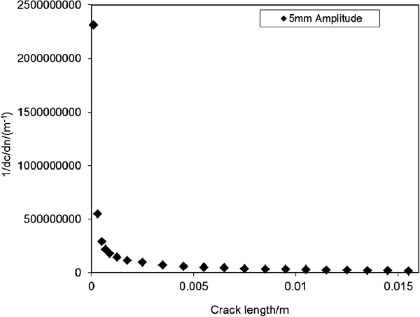
1/(dc/dn) versus crack length for crack growth in cylindrical component in tension at 5 mm amplitude at room temperature
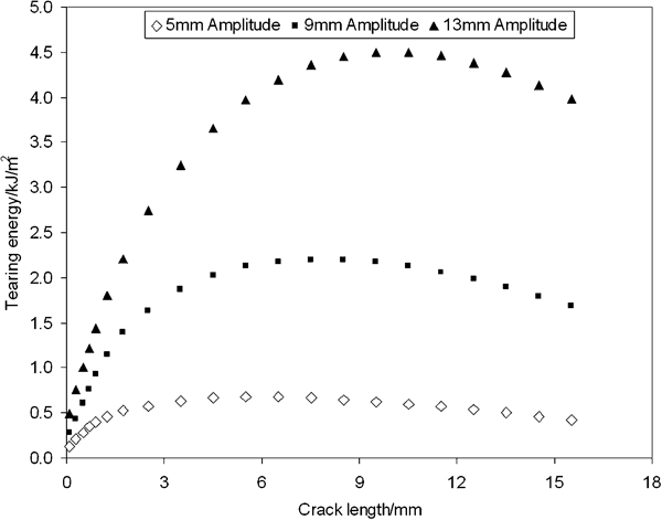
Tearing energy crack length relationship for crack growth in cylindrical component in shear at 5, 9 and 13 mm amplitudes respectively at room temperature
Predicted and measured numbers of fatigue cycles required to grow cracks from estimated rubber–metal bond edge flaw size until specified crack size just before failure
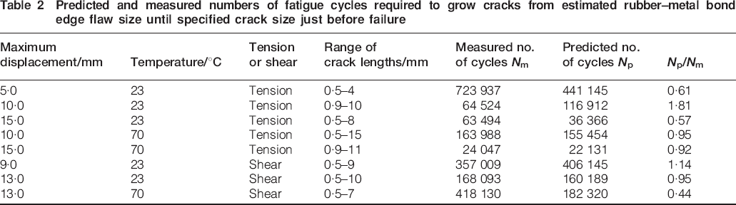
The fatigue life predicted with the fracture mechanics approach generally results in a fatigue life within a factor of 2 to the experimentally measured fatigue life cycles which is excellent especially when considering the extent that the predicted fatigue life depends on the initial size estimate of the flaw at the rubber–metal bond edge of the component. The approach used here of estimating (after careful visual inspection of the rubber–metal bond edge) an initial average flaw size at the rubber–metal bond edge clearly does not take into consideration any small local variations in the flaw size. It is apparent from Table 2 that the method works well for the fatigue life predictions made at both room temperatures and 70°C irrespective of the deformation mode.
Conclusions
The fracture mechanics approach to fatigue life prediction of engineering components has been validated using a cylindrical engineering elastomer component for fatigue crack growth within the ‘power law’ region of crack growth behaviour. The cylindrical geometry of the engineering elastomer component induced rubber/metal bond interface crack growth for both tensile and shear fatigue loading. The fatigue crack growth behaviour was successfully predicted for crack growth at both room temperature and 70±1°C to within a factor of 2 for the cylindrical component. For the first time, the cyclic stress softening associated with fatigue of filled elastomer materials was quantitatively accounted for by softening the dumbbell specimens for the stress strain characterisation and subsequent FEA strain energy calculations at a strain level deduced following the average strain energy density approach. The effect of temperature on the fatigue life of the cylindrical component was also well accounted for by the approach of characterising the material stress strain and the fatigue crack growth behaviour at the test temperature. Considering the irreproducibility of fatigue life predictions in previous work, the accuracy of the fracture mechanics approach method to predict the fatigue crack growth rate with an accuracy of 2 for the fatigue life at both room temperature and 70±1°C is excellent.
Footnotes
Acknowledgements
The authors would like to thank the Swedish Fatigue Network for funding the project, as well as Trelleborg AVS for the supply of the components and the rubber materials for this study. One of the authors, S. Asare, would also like to thank the Department of Materials at Queen Mary, University of London (London, UK) for his research scholarship.