
Abstract
Multiwalled carbon nanotube (MWNT) reinforced epoxy resin composites were fabricated and characterised. Several process variables were investigated using design of experiments. The MWNTs (0·5 wt-%) were dispersed in Epon 862 epoxy resin under various sonication conditions. Young's modulus, energy to failure, glass transition temperature Tg and storage modulus E′ were assessed. The first three were selected in a design of experiment optimisation study. The results indicated that as the sonication intensity and the duration of sonication were increased, the material response of the MWNT/epoxy composite, specifically Young's modulus, energy and Tg, was enhanced. The fracture surfaces of the composites were examined using scanning electron microscopy. Improved dispersion was observed in samples fabricated with increased sonication intensities. The Mori–Tanaka model was used to predict the mechanical properties of the MWNT/epoxy composites and was found to be in reasonable agreement with experimental data. Nonetheless, the experimental results yielded slightly inferior properties to those from the model prediction.
Keywords
Introduction
Carbon nanotubes (CNTs) have exceptional physical properties, which when combined with their high aspect ratios and low density have made them increasingly attractive for the next generation of engineering composites, often termed nanocomposites.1–4 In addition to the improvement of the electrical5 and thermal conductivities6 of polymers at extremely low nanotube concentrations, the improvement of mechanical properties is of particular interest.7 With only a small loading in the resin, typically <5 wt-%, CNTs can improve the mechanical properties significantly. A number of research groups have performed studies on developing high performance polymer composites containing CNTs, ranging between 0·1 and 5 wt-% loading, and demonstrated significant improvements in tensile, shear, flexural properties, fracture toughness and thermal properties.7–13 Allaoui et al.11 showed considerable improvement on tensile modulus and yield strength with 1 and 4 wt-% CNT composites relative to neat resin samples. Elsewhere, 5 wt-% multiwalled nanotubes (MWNTs) were used as reinforcement in an epoxy adhesive and resulted in an increase of ∼50% in the average shear strength.12
Effective reinforcement by CNTs of thermosetting polymers, such as epoxy resins, still presents great challenges. Many groups have observed only marginal improvements, and even a decrease in the composite's tensile moduli, after small additions of nanotubes in an epoxy resin matrix.8 Two critical aspects for the progress and commercialisation of this technology are the dispersion of CNTs in the polymer matrix and the adhesion between the two constituent materials.7, 9, 14–16 For the dispersion of CNTs in polymer matrices, sonication and calendering have been widely used7, 9, 10, 16–20 and will be the scope of the present work. Even though there are many research efforts addressing nanocomposites, they do not seek to quantify the optimal parameters of the fabrication process, which must be understood before there can exist a significant advancement in the processed nanocomposite.
There exists a considerable amount of research that has sought to link the final processed nanocomposite part with the theoretical, and many authors choose to employ the micromechanics based Mori–Tanaka model in some fashion for the prediction of the mechanical properties for nanocomposites.21–27 Tucker and Liang28 discussed applicable micromechanic models for unidirectional inclusions and concluded that the Mori–Tanaka method, as expressed by Tandon and Weng29 with the analytical correction given by Tucker and Liang,28 is a reasonable method for the range of inclusion aspect ratios and volume fractions for which we are concerned with. Micromechanic models, including the Mori–Tanaka model, traditionally assume that the inclusions are well represented by straight ellipsoidal inclusions with a perfect bond existing between the inclusion and the surrounding matrix and that there is a homogeneous spatial distribution of inclusions. Recently, some authors have discussed the need to study flexible inclusions. In particular, there are those who have considered both waviness and debonding between the CNT and the polymer matrix,30, 31 but that is beyond the scope of the present work and will be left for future studies.
In this study, the sonication component of fabrication was investigated to optimise the overall fabrication process for the CNT/epoxy nanocomposites. The design of experiments (DOE) technique32 was used to design the appropriate set of experiments and to analyse the results efficiently. Tensile tests and dynamic mechanical analysis (DMA) tests were performed for characterising the samples. The fracture surfaces of MWNT/epoxy resin composites were examined using a scanning electron microscope (SEM) to identify the failure modes of the composites. The predicted mechanical properties were obtained with the Mori–Tanaka micromechanics model. Simulation results were compared with experimental results to provide a theoretical upper bound for the ideal fabricated nanocomposite, and deficiencies are discussed.
Micromechanics modelling for mechanical properties
The orientation of an individual CNT within the nanocomposite is fully realised by a single vector in three-dimensional space for the straight inclusion assumption. This vector is defined by the unit vector 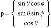
 . The stress and strain are related through Hooke's law as σij = Cijkl = ϵkl, where the six independent components of stress and strain can be expressed in contracted notation as σm = Cmmϵn, where m, n∈{1, 2, …, 6} (see e.g. Ref. 35 for a full discussion).
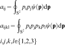
Coordinate system and definitions of θ, φ and
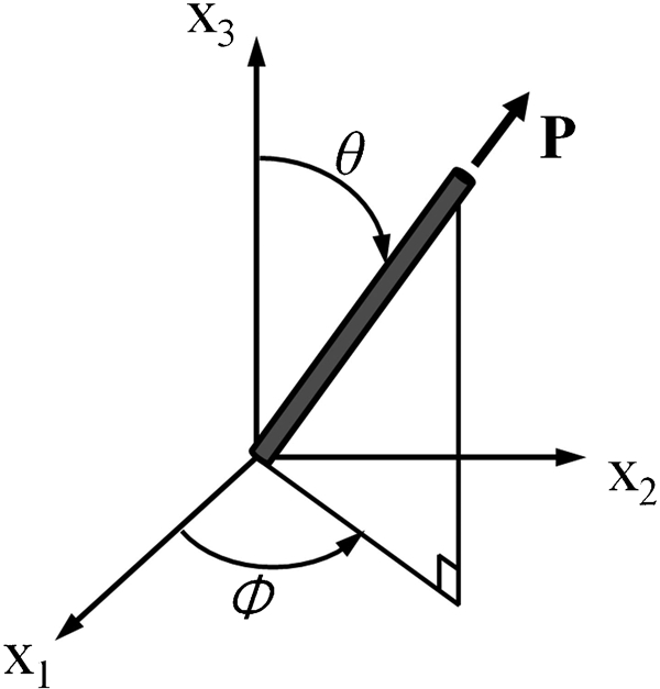
In this analysis, the Mori–Tanaka model (presented in Appendix for completeness) was applied for determining the unidirectional stiffness tensor of the resin/nanotube system. Table 1 lists the five independent components of the transversely isotropic stiffness tensor for our CNTs (Cf in Appendix), as provided by in Ref. 27. In the reference, the components were obtained for single walled CNTs by molecular dynamics calculations and an equivalent continuum model. In this work, however, multiwalled CNTs (MWNTs) were used for the experiments. The selection to employ single walled CNT properties in lieu of MWNTs in the model predictions was based on the lack of studies presenting the complete MWNT orthotropic stiffness tensor. Moreover, a Young's modulus value for MWNT of 450 GPa was used in Ref. 36. Therefore, the values in Table 1 were used as inputs for the model results in this work. For the isotropic epoxy matrix Epon 862, we used the Young's modulus and Poisson's ratio of 2·359 GPa and 0·33 respectively, where the Young's modulus was obtained via an in house experimental tensile test, and the Poisson's ratio came from Refs. 37 and 38.
Carbon nanotube independent parameters and elastic stiffness components/GPa27
Once the underlying unidirectional stiffness tensor is obtained from equation (10) in Appendix, the elastic constants may be averaged with the known nanotube probability orientation distribution function ψ(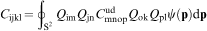
Experimental
Materials
This study employed MWNTs synthesised by chemical vapour deposition and manufactured by Sigma-Aldrich Inc. The outer diameter, inner diameter and length of the CNTs before sonication were 20–30 nm, 5–10 nm and 0·5–200 μm respectively. The matrix material consists of Epon 862 epoxy resin and EpiCure W curing agent, both of which were manufactured by Miller-Stephenson Chemical Co.
Fabrication process
Precalculated amounts of CNTs (0·455 g) and epoxy resin (72 g) were weighed and mixed together in a beaker such that the weight fraction of CNTs was 0·5 wt-% with respect to the resin and curing agent. Tip sonication, using a Misonix Sonicator 3000, was employed to disperse the CNTs in the epoxy resin. During the sonication process, the beaker containing the CNT/resin mixture was submerged in an ice bath to prevent heating of the solution and premature curing due to thermal heating. After sonication, the epoxy and CNT mixture was cooled to room temperature, followed by adding a curing agent (EpiCure W) by mechanical stirring at 500 rev min−1 for 5 min. The mixture ratio of Epon 862 and EpiCure W was 100∶26·4 (72 g/19 g), as suggested by the manufacturer. Upon completion of the sonication and mixing processes, the CNT/resin mixture was degassed in a vacuum oven at room temperature, poured into a casting mould and allowed to cure at 177°C for 3 h in a hot press.
Sample characterisation
Tensile specimens were prepared, and tests were performed in accordance with ASTM D638 and D882. A tabletop universal tester (Autograph AGS-J manufactured by Shimadzu) was used. Dog bone shape tensile test specimens (58 mm in overall length, 3·7 mm wide in the narrow section and 0·8–1·1 mm in thickness) were cut using a laser cutter (Laser Platform made by Universal Laser Systems). Tensile tests were performed at a crosshead speed of 1 mm min−1 until specimens failed, and a camera extensometer was used to measure the strains in situ. The morphology of the fracture surfaces of the composite samples was observed using a JEOL JSL-7401F SEM to investigate the CNT/matrix interfaces and the CNT dispersion in the matrix.
The dynamic mechanical properties, glass transition temperature and storage modulus, of the nanocomposite were investigated by a dynamic mechanical analyser (DMA 2980; TA Instruments) for rectangular samples (∼3·3 mm in width and ∼1 mm in thickness). DMA was performed in tensile mode at a constant frequency of 1 Hz and a heating rate of 5°C min−1 beginning from room temperature to 250°C.
Design of experiments for improvement of manufacturing process
The DOE is a collection of statistical and mathematical techniques that have been demonstrated to be useful for developing, improving and optimising many industrial processes. In general, an experiment includes multiple input variables and process variables, referred to as the control factors, each of which can potentially influence the performance measure (also referred to as the quality characteristic) of the product or process which serves as the response variable.32, 40
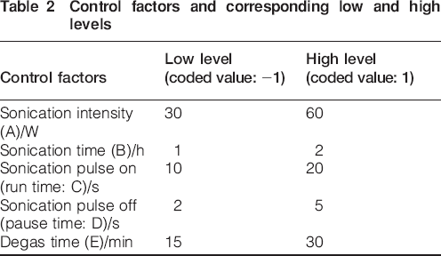
A two-level factorial design was used, which has been demonstrated to be the most efficient approach for experiments involving the study of the effects of two or more factors.32, 40 The five control factors selected to be studied are listed in Table 2. The following test used one-quarter fraction design, typically labelled as a
 design, which includes eight experimental tests for five control factors. Sonication was used to mix CNTs and resin in the pulse mode selection of on/off. The measured responses were Young's modulus, energy absorbed before specimen failure from tensile tests and glass transition temperature Tg obtained by DMA. Design Expert, by Stat-Ease Inc., was used to set up the input parameters for the physical experiment and then to analyse the fabricated product's results.
Control factors and corresponding low and high levels
Results and discussion
Simulation results
The volume fraction of CNTs is related to the density of the constitutive materials and their respective weight fractions as follows41
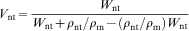

It was assumed that there was air in the hollows of CNTs because the ends of CNTs were assumed to be closed.
Based on the manufacturer's specifications for the CNTs, it was assumed that the final processed CNTs have an outer diameter of 25 nm, length of 100 μm and aspect ratio of 4000. It was also assumed that the bonding between the CNTs and the polymer matrix was perfect; all the CNTs were straight rods; and the MWNTs were homogeneously dispersed. In this research, numerical simulations were performed using MATLAB (The MathWorks Inc.). Two extreme cases were investigated within the simulation, i.e. unidirectional alignment along the x axis and fully isotropic alignment (a uniform random orientation).
With the two extreme cases, we hope to capture some general trends and provide bounding conditions for the expected behaviour of structures for nanotube orientation conditions that fall somewhere in orientation space between perfectly aligned and isotropic. The results are shown in Fig. 2, where, as expected, it is quickly evidenced that Young's moduli increase with increasing CNT loading. In Fig. 2a, the Young's modulus in the direction of alignment of an aligned composite is higher than that of a composite with an isotropic orientation of nanotubes. However, as observed in Fig. 2b, the Young's modulus in the direction transverse to alignment experiences the reverse behaviour between the unidirectional and isotropic orientations. The randomly orientated composite yields a higher in plane shear modulus value than the aligned composite, as depicted in Fig. 2c, and as the packing density increases, this trend becomes more apparent. Interestingly, as shown in Fig. 2d, the Poisson's ratio for randomly oriented composites on the aligned face in the transverse direction decreases with CNT loading, whereas there is a nominal increase in the Poisson's ratio with increasing CNT volume fraction for the aligned composite. In the remainder of this study, we selected the isotropic orientation model for experimental comparisons due to observations made on the test samples demonstrating an orientation condition closer to random in space.
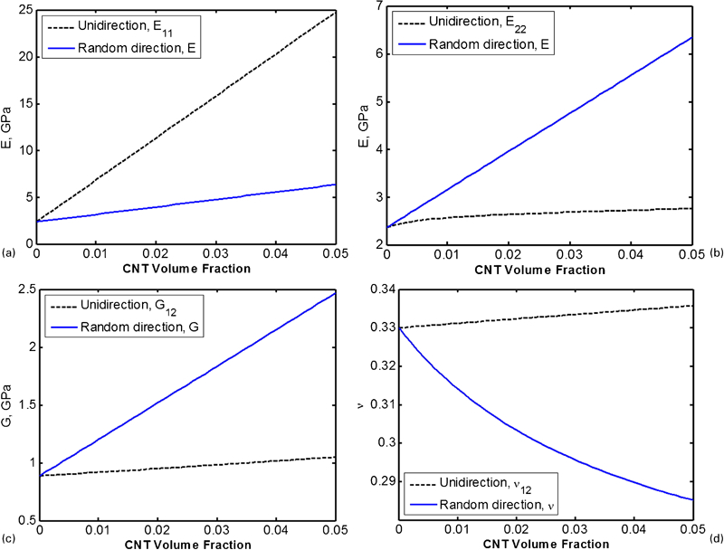
a longitudinal Young's modulus; b transverse Young's modulus; c in-plane shear modulus; d in-plane Poisson's ratio
Experimental results
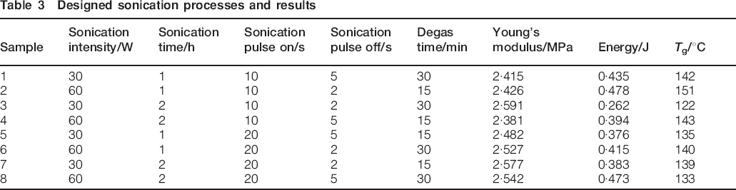
Table 3 presents the tensile test results obtained at the design points developed during the DOE phase for each of the three responses, i.e. Young's modulus, energy and glass transition temperature Tg. For the tensile test, each sample had five test specimens, and the results show the average values. Conversely, for the DMA test results, a single specimen was tested for each sample.
Designed sonication processes and results
Microstructure
To investigate the microstructures of the test samples, the fracture surfaces were studied using SEM imaging. The samples were frozen in liquid nitrogen and then fractured. Multiple spots of the samples were observed, and several representative SEM images are shown in Fig. 3. The arrows in Fig. 3a, b and c for samples 1, 5 and 7 respectively indicate CNT aggregates with poor dispersion. Conversely, sample 4, as shown in Fig. 3d, does not experience the same aggregation, and the arrows show the relatively good dispersion of the CNTs. Since the sonication intensity of samples 1, 5 and 7 was 30 W, the lowest of the two sonication intensities studied, it may be speculated that a higher intensity generated better dispersion, as demonstrated by sample 4, which was subjected to a 60 W sonication intensity.
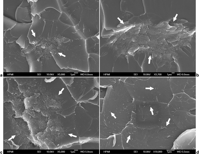
Images (SEM) of select samples showing poor dispersion (sonication intensity of 30 W) in a sample 1, b sample 5 and c sample 7 and good dispersion (sonication intensity of 60 W) in d sample 4
Tensile tests
Young's modulus results were analysed using Design Expert. The analysis of variance results indicated that the resulting DOE model was not statistically significant, thus implying that the selected process parameters do not affect the results significantly. However, this warrants further investigation. The regression model, in terms of coded factors A, B, C, D and E listed in Table 2, for Young's modulus EYM, is given as
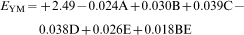
Assuming that the CNTs in the suspension are randomly orientated, the theoretical Young's modulus for a 0·5 wt-% CNT (a volume fraction of 0·29%) is 2·595 GPa. The observed Young's moduli listed in Table 3 are smaller than the theoretical modulus. Recall that, in the simulation, it was assumed that the CNTs were well dispersed (or individually exfoliated) and distributed, the bonding between CNTs and epoxy matrix was perfect and the CNTs were straight and without curvature. However, in the experimental samples, dispersion was not perfect, as evidenced in the SEM images of Fig. 3, where aggregates are observed in most of the samples. In Fig. 3d, pulled out CNTs were observed, which suggests that there were imperfect interfacial bondings between CNTs and epoxy matrix. Interfacial bonding may be improved by functionalisation of CNTs16 but at the cost of individual CNT structural and conductive properties. In the test samples, many bent CNTs were found, which will also affect the mechanical properties of nanocomposites.30
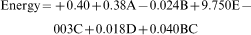
In addition to the Young's modulus, another crucial material property to consider is the absorbed energy to failure. Tensile tests were performed on each of the samples, and the specimens were loaded to failure to capture the energy to failure. The results from the tests were analysed in Design Expert to construct the regression model in terms of the coded factors in Table 2 with a resulting model given as
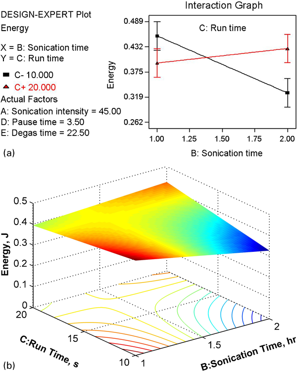
a interaction graph of B and C factors; b response surface of B and C factors
DMA
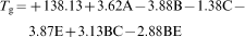
The DMA results were used to obtain the glass transition temperature Tg, and the results obtained from each of the samples are listed in Table 3. The resulting regression model from the DOE analysis is expressed as
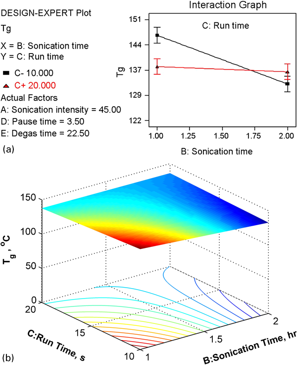
a interaction graph of B and C factors; b response surface of B and C factors
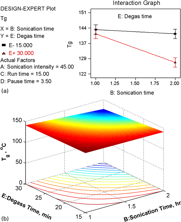
a interaction graph of B and E factors; b response surface of B and E factors
The DMA results were used to study the storage moduli of the nanocomposites, and as observed by the results in Fig. 7, the storage modulus of the nanocomposite is higher than pure epoxy resin for low temperatures. However, the Tg of the nanocomposite is lower than that of pure resin, as shown in Fig. 8. The explanation of Ash et al.42 can be applied to this. In nanocomposites, the region surrounding the CNTs that are not fully wetted by the polymer behaves as voids in the polymer matrix. The matrix, therefore, exists as a porous system with surface-like mobile regions existing around each CNT. This increases mobility through the void regions raising the bulk mobility of the polymer, thus lowering the observed Tg.42
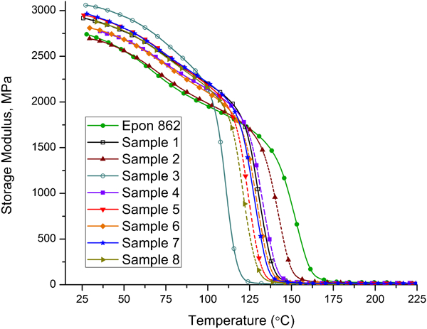
Storage modulus from DMA
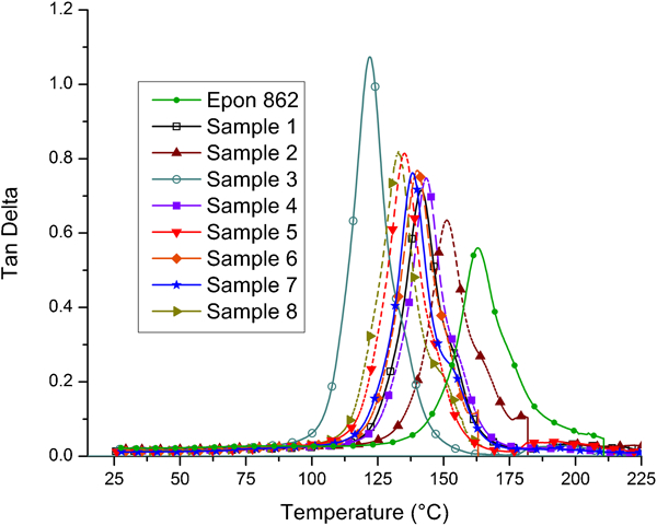
Tan delta from DMA
A brief visual analysis of Table 3 and Fig. 3 states that, generally, samples with higher sonication intensity have higher Tg, and it is hypothesised that this was due to the fact that a higher sonication intensity results in better CNT dispersion. The CNTs, which are fully wetted by the polymer, limit the mobility of neighbouring polymer molecules, thus increasing the Tg of the composite.43 The better dispersed the CNTs, the higher the Tg, as they provide more ‘immobilised’ sites.
Young's modulus and the storage modulus are compared in Fig. 9 for each of the eight samples. The presented storage moduli of the samples was selected from the DMA results at 35°C, and the results show that there are similar trends for Young's modulus and storage modulus. There appears to be a correlation between Young's modulus and storage modulus in that as the modulus of one is increased, the other modulus increases as well.
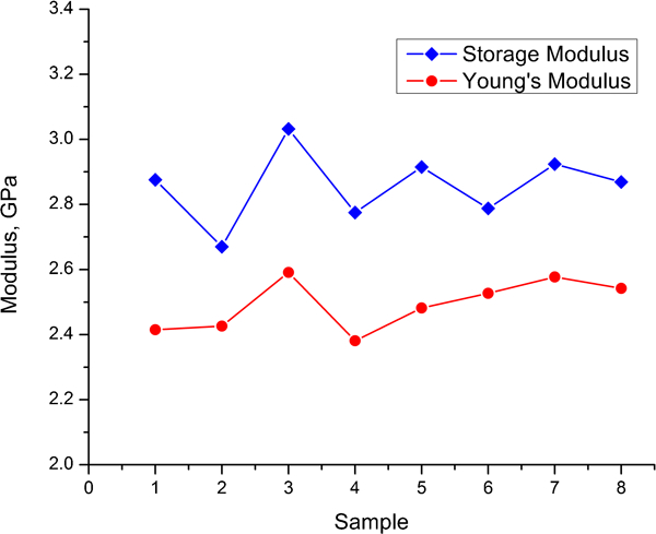
Comparison of Young's modulus and storage modulus
Optimisation of sonication process
Numerical optimisation using the regression models of the samples was performed using Design Expert to maximise Young's modulus, energy and Tg. The search areas were 0–90 W for sonication intensity, 0–2 h for sonication time, 10–20 s for pulse ON time, 2–10 s for pulse OFF time and 0–30 min for degas time. The maximum sonication intensity for Epon 862 epoxy and CNTs was checked experimentally, and the intensity was 100 W. To protect the sonication machine, 90 W was chosen for maximum search space. To lower the degree of CNT shortening due to longer sonication time, 2 h was selected for maximum sonication time. A 20 s pulse ON time was selected for maximum search boundary to keep the sonicator tip from heating up, thus damaging the equipment. For maximum pulse OFF time, 10 s was selected, which was half of the maximum pulse ON time. The search area of degas time was chosen based on the search spaces for the experimental set in the sections on ‘Design of experiments for improvement of manufacturing process’ and ‘Experimental results’. The following process setting was suggested by Design Expert as the possible optimum value within the search space
sonication intensity: 90 W
sonication time: 2 h
run time: 20 s
pause time: 2 s
degas time: 24 min.
In the regression models from equations (8) and (9), increasing the sonication intensity and decreasing the sonication time were recommended. To maximise each of the three responses, i.e. Young's modulus, energy and Tg, however, high intensity and longer time of sonication are recommended, as shown in the optimised result. With the optimised process, a nanocomposite sample was manufactured and tested. The results were 2·568 GPa for Young's modulus, 0·438 J for energy and 162°C for Tg. The additional optimisation responses are shown in Fig. 10, which shows the DMA results, including storage modulus and tan delta. Observe that the response Tg was improved significantly as compared to the tan delta graphs in Fig. 8.
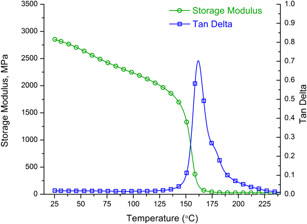
Dynamic mechanical analysis results of sample manufactured with optimised process
The improvement in the Young's modulus from the DOE optimisation was improved by a 0·209 GPa increase through the above mentioned processing conditions. From this number alone, it is unclear if there is further room for improvement for the investigated system, but this is answered from the theoretical model. The system presented in equation (4), for an idealised CNT/resin system, was composed of well dispersed, straight rods with perfect bonding, and the constitutive equation predicts a Young's modulus of 2·6 GPa. Thus, the DOE optimised system with 0·5 wt-%CNTs has an improvement of 88·6% of the theoretical system as compared to the pure resin system. This improvement is considerably better than several of the samples shown in Fig. 9 but still leaves room for improvement in a future study. The difference observed between experimental and predicted data may have resulted from assumptions of perfect CNT matrix bonding, CNT straightness, their perfect dispersion, etc. It may be expected that with the development of improved processing technologies, the experimental data may begin to mirror theoretical predictions.14 Furthermore, future work should consider the effect of CNT waviness as well as the degree of dispersion, and interfacial behaviour, for more accurate predictions.
Conclusions
In this study, the micromechanics model of Mori and Tanaka was employed to predict the mechanical properties of a CNT/epoxy composite. The processing conditions, i.e. sonication and degassing, were studied to improve the manufacturing process of a nanocomposite. The results from the micromechanics model and the improved experimental results were in reasonable agreement. The experimental results implied that a higher sonication intensity generated better dispersion. From the optimisation procedure, it was observed that a higher sonication intensity and longer sonication time improve Young's modulus, energy and Tg. In the DMA test, the CNT/epoxy composites had lower Tg than the neat resin, but improvements in Tg were made as the dispersion was enhanced. Based on the observations in the present work, the results indicate that further enhancing the nanotube dispersion may generate enhanced mechanical properties.
Footnotes
Acknowledgements
Thanks are due to Drs J. Bao and J. G. Park from High-Performance Materials Institute, Florida State University, who assisted in sample fabrication, mechanical testing and SEM imaging.
Appendix
This article is part of a special issue on the 2nd International Conference on Engineering Against Fracture