
Abstract
A typical metallic main landing gear fitting was designed and manufactured in carbon fibre reinforced polymer (CFRP). The component features wall thicknesses of up to 90 mm due to massive loads and compact dimensions. The aim was to reduce the weight and to provide a distinct cost benefit. Two prototypes of the fitting were produced. Based on the gained manufacturing experience the cost benefit was evaluated for a possible serial production. A new open mould manufacturing process was chosen in order to maximise flexibility and to reduce development costs. The entire manufacturing process was continuously optimised and refined. The gained experience was implemented and combined in a final study of a serial production of the CFRP fitting. In the last step the gained data were compared to the standard metallic fitting. For this example, ultra thick laminates (UTLs) provide a significant cost and weight benefit. The composite design can be categorised as highly manufacturing driven.
Ultra thick laminates, Cost analysisIntroduction
The following study presents a cost and weight evaluation of a compact landing gear fitting, the so called ‘side stay fitting (SSF)’, in carbon fibre reinforced polymer (CFRP). The component was developed in the framework of the European project ALCAS (wing platform, see also Ref. 1) by EADS Innovation Works. The design was based on a standard landing gear kinematic and the fitting in question supports a side stay of the main landing gear leg. A detailed description is given in Refs. 2 and 3 (see also Fig. 1). Similar to its metallic counterpart, the new CFRP fitting has to support an axis from a side stay in two locations. In addition, the component is connected to the wing spar and lower wing cover. Most loads are transferred to the spar. Figure 1 also illustrates the final CFRP fitting mounted on the wing spar and lower cover.
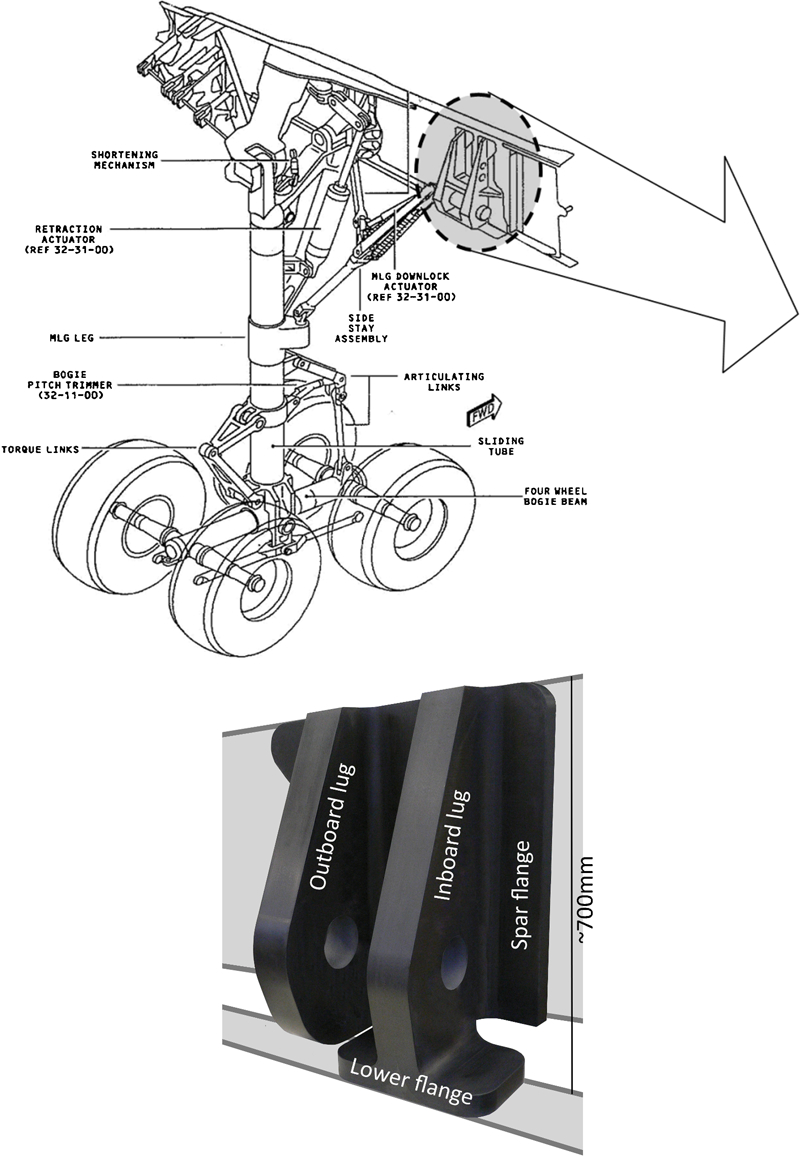
Main landing gear and first CFRP fitting prototype
Ultra thick laminates (UTLs)
Laminates are commonly applied to thin and shell such as structures with limited curvature. However, composite materials are increasingly being used for compact components with significant curvature and out of plane load transfer. Ultra thick laminates are used to substitute common metallic fittings and load introductions with large loads. Here, the overall goal is to save weight and manufacturing costs.
The SSF was developed as a prototype with the emphasis on a composite friendly design while using a flexible and adaptable manufacturing process. A composite friendly design offers the possibility to use the material to its best advantage and a flexible manufacturing process offers least interference during the design phase of the component. Closed mould processes severely limit the design freedom early in the design phase, while adding numerous unknowns concerning the manufacturing of UTLs. Evaluating these unknowns would greatly increase the scope of the project. At the same time laminate quality is of the utmost importance and defects such as fibre undulations and dry spots have to be avoided.
The paper is a case study of a possible serial production using an adapted open mould manufacturing process. The presented data are based on the manufacturing of two prototypes and numerous manufacturing trials, used to optimise the process.
Manufacturing of UTL
For UTL a new derivative of the standard open mould vacuum assisted process (VAP) was used (see also Ref. 4). Curing thick composites and thus large amounts of resin potentially lead to an uncontrolled thermal event due to the large amount of exothermal heat generated by the chemical process. Therefore, a new process, referred to as ‘integrated tooling’, was applied, as described in Ref. 2. Here the laminate is manufactured in steps, where essentially dry fibres were applied on top of cured but untempered sections until the required thickness was reached. The SSF was manufactured with non-crimped fabric (NCF) and the RTM6 resin system. The standard curing cycle was adjusted (reduced temperature) to prevent overheating.
Subcomponents and final fitting
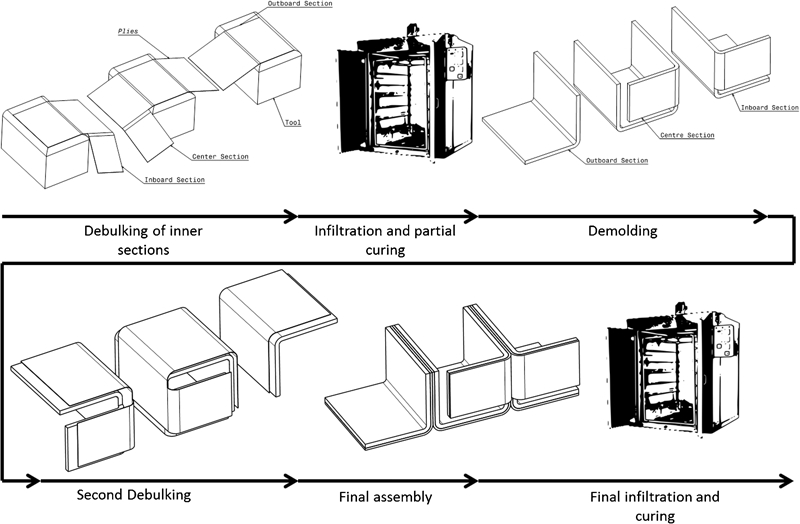
The SSF manufacturing process can be split into the manufacturing of the subcomponents and the assembly of these, to form the final fitting. In general there are three different folding processes, one for each subcomponent of the fitting, as shown in Fig. 2. None of these folding processes create a fibre overlap. The centre section, however, will create an enclosure due to the spring back effect. Demoulding was facilitated by using an adjustable tooling. The dry NCF fabrics were consolidated, infiltrated and cured to reach a thickness of 30 mm. In the second step additional plies were added on top of the precured sections, until a total thickness of 45 mm was reached. The process is hence referred to as ‘integrated tooling concept’, since the precured laminate serves as a tooling for the next portion of the dry fibrs. Finally all sections were arranged in an assembly, infiltrated and cured again for the inner dry NCF. The entire laminate was tempered in a final stage.
Subcomponent manufacturing and assembly of fitting
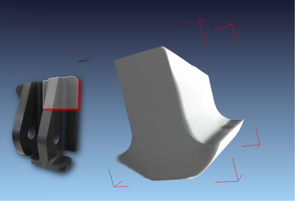
Figure 3 shows a 45 mm thick radius section. Fibre misalignment and undulations were reduced to a minimum using the stacked debulking and infiltration process.
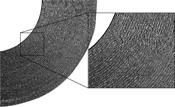
Curved section of 45 mm thickness
The entire manufacturing process of the subcomponents hence consists of the following steps:
cutting
ply positioning
debulking
VAP set-up
curing
cooling
demoulding
peel ply removal
trimming
NDT.
These steps were repeated for the inner sections of the final fitting. After computer numerical control milling all bushings were assembled. All manufacturing steps were precisely protocolled for the first and second prototype in order to document the required man hours, material and machining times. The monitored values can be summarised into one final figure. Potential for optimisation is identified and incorporated into a study of a possible serial production. Figure 4 illustrates the SSF with all required metallic bushings and washers.
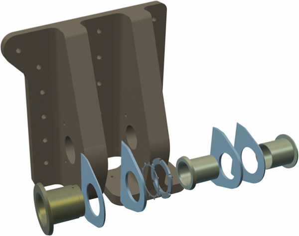
Fitting with metallic bushings all washers
Possible improvements
The following section includes several process improvements for the described manufacturing process. The study is based on the gained experience collected during the duration of the project. A large amount of full scale test components were designed and built. These were primarily used for structural testing but also provide valuable data for process improvement.
Cutting
For both prototypes the NCF fabric was cut by hand. The process can be highly automised, revealing potential for time and cost reduction. In addition, the size and shape of the cut also changes with its actual position in the final fitting. For manual cutting the cutting pattern remained constant. With an automised cutting process each ply can be adjusted in size to reduce the amount of waste. A correct placing order of the plies is essential, also with respect to the fibre orientation. Each ply is thus unique and requires the information of orientation and size/shape.
Ply positioning
Ply positioning can be automised using a laser projection system, both to increase the process speed and in order to increase accuracy, as shown by Mason.5 This is particularly important if a large amount of individually tailored plies are used.
Debulking
Debulking was repeated every 10–20 plies to avoid fibre undulations (the degree of compaction in third direction is directly proportional to the preform thickness). Debulking was performed with a flexible vacuum membrane and the binder was activated with IR heaters. The process was time consuming and achieving an even temperature distribution difficult. A solid and preheated debulking tool can be designed and used in order to shorten the labour intense debulking process.
VAP set-up
For the manufacturing of the fitting an open mould process was chosen to provide maximum flexibility for possible design changes. Closed mould processes quickly hamper the design liberty once tools are manufactured. The applied VAP is a standard procedure (see also Ref. 4). The amount of consumables used may be reduced for a serial production process. For the manufacturing of the prototypes consumables were used with significant oversize to prevent complications. Special care should be taken with the infiltration sequence of large components in order to avoid entrapped air pockets.
Curing
For the curing of UTL an adapted cycle was used to prevent resin overheating due to exothermal energy released by the process. Several manufacturing trials with thick laminates, ranging up to 80 mm, were conducted in order to adapt the standard curing cycle. For the final cycle a conservative approach was chosen with an extensive curing time at 110°C. Curing time can, however, be reduced significantly while still maintaining thermal stability. In practice, the laminate thickness that is cured in a single shot does not exceed 45 mm. The curing time has a direct influence on the oven lead time.
Cooling
Cured subcomponents hold extensive thermal energy which has to be dissipated before these can be used as moulds for the inner preforms. This was of little concern during the prototype manufacturing, but for serial production the slow cooling process might hinder the following processes. The precured subcomponents are required for an additional debulking step. A forced cooling process may hence be applied to reduce the manufacturing time.
Demoulding
Demoulding from rigid and enclosed tools (as is the case for the centre subcomponent) became difficult due to the inevitable process induced deformation of the laminate. The deformation of the laminate has to be considered and incorporated into the design of the tooling. Tools can be designed to facilitate the demoulding process, as shown in Fig. 5. The figure illustrates a flexible tooling which compensates for the deformation of the laminate. The two sides of the tooling are hinged and unlocked by removing a horizontal stabiliser.
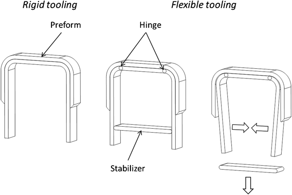
Suggestion for improved male VAP tool
Trimming
For the prototype, each precured subcomponent was edge trimmed. This intermediate trimming process, which usually is performed after the first curing cycle, can be avoided completely by using tailored plies. The size and shape of the tools is not affected. For the final fitting, conventional computer numerical control milling can potentially be replaced by water jet cutting. Cutting tests on UTLs have been conducted with good results on up to 90 mm thick sections. Computer numerical control milling might be considered for high tolerance sections, such as the holes for the bearings.
NDT
Different options for NDT were investigated during the development of the fitting. For all subcomponents standard ultrasonic inspection was performed, as well as phased array for curvatures. Accurate results were achieved for these components due to their limited thickness. For the entire fitting different options such as computer tomography were investigated. However, further studies are required to provide a cost effective and reliable NDT method for UTL. Figure 6 illustrates a u-CT part volume inspection of the fitting.
Part volume inspection at one of T-sections
Cost evaluation for serial production
For the analysis of the cost potential of the composite fitting a production rate of 26 units per month was assumed, sufficient to equip 13 aircraft per month. Involved manufacturing steps were analysed to evaluate possible potential for optimisation and automation according to the described steps above. The required resources are as follows:
two workers: a minimum of two workers is assumed according to the experience from the manufactured prototypes
computer numerical control machine (possibly water jet cutter): the machine is required for the final machining of the component
NDT facility (US scan): as part of the quality assurance, each subcomponent as well as the final fitting need to be checked for defects. For that purpose a multichannel US scanner is used
curing oven: a standard oven is used for the VAP. An automated resin infusion system with an integrated resin heater and vacuum pumps are required
ply cutter: ply cutting can be automised, as described above. The NCF is fed from a roll onto a conveyor belt
ply positioning robot: after cutting, plies can be directly used for debulking in order to reduce the required storage space
debulking/VAP table: debulking and the VAP can preferably be conducted on the same table. This also reduces the amount of handling
three moulds: the moulds are used for debulking, infusing and curing. In addition, the tools are used to support the first CFRP sections when the inner dry fabrics are applied for the final set-up. Currently simple stainless steel sheet metal tools are used.
For the following study of a serial production a total utilisation factor of u = 0·75 was assumed. A full utilisation factor would potentially lead to a jamming of the process according to the queuing theory, where the queuing time is defined as

The capacity utilisation was summarised and compared to the availability in order to determine the required amount of any resources at the given production rate. In addition, a failure rate of kf = 10% was applied. Material costs include the resin, NCF, VAP consumables and the metallic fittings and bushings. The used quadraxial NCF is available with a width of 1·4 m. For the cutting process two different types of waste were identified (see Fig. 7):
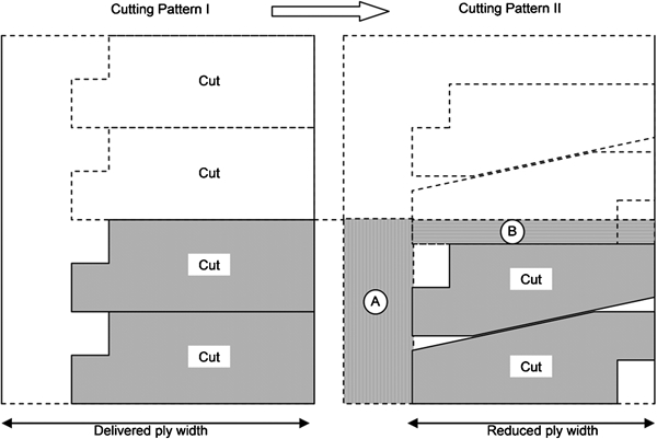
Initial versus optimised cutting pattern
type A: caused by the size and shape of the delivered NCF material
type B: caused by the size and shape of cut.
The lugs of the SSF have a wedge shaped outline. This outline was not considered when cutting the plies for the prototype. Cutting pattern II illustrates an optimised outline with minimum excessive material; thereby reducing waste of type B. In addition, the design width of the NCF causes waste classified as type A. Here the width or cut could be adjusted to further reduce material waste.
To estimate the manufacturing costs an overhead calculation was performed according to Birkhofer6 and Macha.7 The calculation scheme is illustrated in Fig. 8.
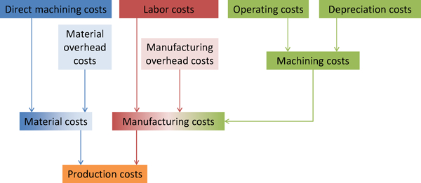
Calculation scheme for SSF overhead costs, applied to all manufactured components and investigated serial production
Material overhead costs include goods inspection, storage and supply. The material overhead rate was chosen as kMatOC = 5% and defines the expenses due to handling, storage, etc. Labour costs were calculated with the number of required workers per month and the hourly wage rate. The manufacturing overhead costs include costs for tools, auxiliary and working materials. They were calculated proportional to the labour costs, assuming that these costs are generated by manual labour. The manufacturing overhead rate was chosen as kManOC = 4% and represents general resources which were required for the manufacturing process. The machining costs consist of the annual depreciation, maintenance, imputed interests and machine operating costs. External manufacturing steps performed were included with hourly rate costs. The annual depreciation, maintenance costs and the imputed interests were divided by the demanded lot size to calculate the costs apiece. The maintenance costs were calculated with the investment costs, the number of machines and the maintenance rate. The maintenance rates were chosen from 2 to 8% to represent the expected maintenance effort, the vacuum table (used for compaction), for example, has a high maintenance rate (8%) due to the sensitive membrane. The life time of the moulding tool was chosen to one year; therefore, the maintenance rate was set to 100%. The imputed interest was calculated with a rate of 6%, based on half of the investment as the capital equipment. The distribution of the costs is shown in Fig. 9. The distribution shows that the direct material costs present the major share of the total production costs, due to high costs of the used materials.
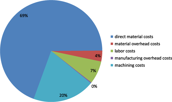
Manufacturing cost distribution for second prototype manufacturing
Direct material costs certainly present the largest fraction. The figure above includes the costs of bushings and load distribution plates as manufactured for the prototype. A cost reduction of 30% was assumed for serial production, since programming costs and rigging time will be reduced per piece for larger quantities. The distribution of the direct material costs is given in Fig. 10. Here the NCF and the metallic bushing consume the largest portion.
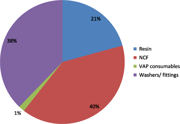
Direct material cost distribution for serial production
The overhead calculation was performed both for the prototype manufacturing process and for the automated manufacturing described above. The values derived from the calculations and the costs for a metallic SSF are compared in Fig. 11. Using the automated VAP for serial production currently provides a cost reduction of 20% compared to the metallic fitting. However, the CFRP fitting for ALCAS is produced at a scale of 0·7. For the comparison below, the cost of the metallic fitting was scaled according to its reduced volume (0·73 = 34%). Basic assumptions for the metallic fitting, such as lot size, useful life, labour costs or the imputed interest rate, are likely to differ from the values chosen in this calculation of the CFRP fitting. The calculation does however provide an indication of the potential of UTLs used for a highly loaded fitting.
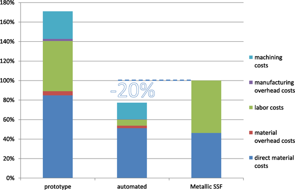
Comparison of production costs of SSF, related to initial productions costs of prototype
Compared to the CFRP fitting, the metallic counterpart presents a complex forged metallic shape. A high degree of automation is assumed for the CFRP fitting, but considered feasible, based on the gained manufacturing experience.
Weight potential of UTLs
The final weight of the component is shown in Fig. 12. Two different prototypes were manufactured, of which the first featured equal wall thickness for both lugs. The second prototype incorporated a reduced lug thickness on the outboard side based on results from the finite element analysis. Components for the ALCAS Airliner wing were designed at a reduced scale of 0·7. Available weight data of a regular metallic fitting was scaled according to its volume.
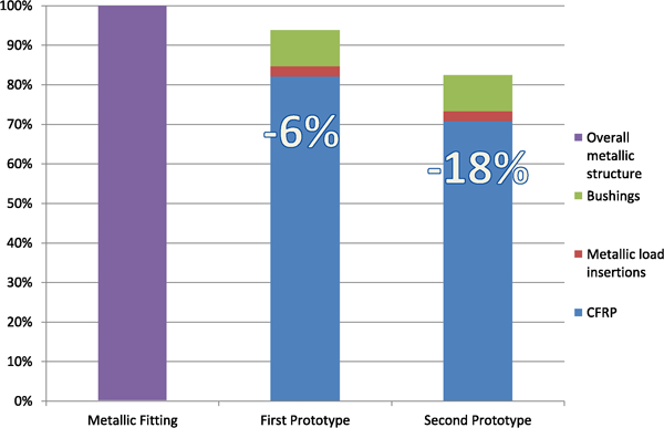
Weight comparison of standard metallic fitting and CFRP counterparts, first and second prototype
The fitting itself is a not a typical composite structure due to its compact design and the large multidirectional loads. However, a weight reduction of 18% was achieved for the current configuration. Part of the challenge of designing a structure using composites was to apply material only where needed without adding complexity to the manufacturing process or the ply lay-up. The design of the fitting was reduced to a minimalistic shape and under the given constraints of the main landing gear, the thickness of the material remained as the main parameter to increase the component strength. While the first prototype featured a constant wall thickness of 90 mm for both lugs, the second prototype had a reduced wall thickness of 60 mm for the outboard lug (see Fig. 13). The outboard lug mainly was subjected to in-plane loads, which were less critical. On the outboard side, however, large out-of-plane loads had to be dispersed. For a more detailed description of the analysis the reader is referred to Refs. 8 and 9.
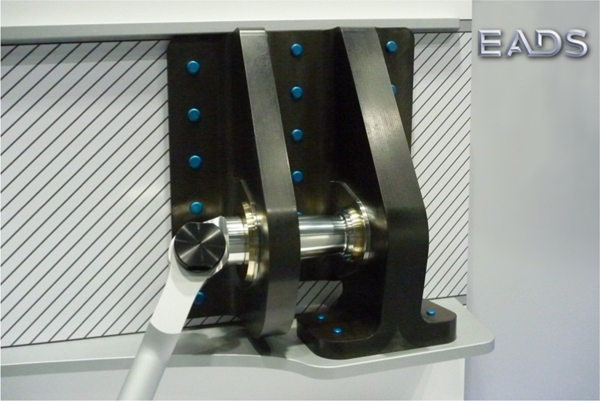
Second SSF prototype with asymmetric lug thicknesses, mounted to demonstrator display unit
Figure 14 illustrates the weight distribution of the different materials used for the fitting. CFRP clearly dominates the structure, both weight and cost wise.
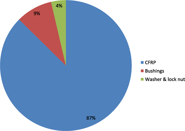
Weight distribution for second prototype
Discussion
Dominant failure modes are matrix driven and usually occur in the radius section or close to the load introduction itself (lug). Commonly a combination of transverse shear and normal stress leads to failure. An overview is given in Ref. 8. An improved stacking sequence has been tested and analysed and was used for the fitting.9 In a conservative approach, the improved strength values generated by the material tests were not implemented in the final sizing of the structure. However, for the primary failure mode for the load introduction region, an increase in strength of ∼25% was observed. Further weight savings would therefore require additional tests to fully exploit the potential of the material.
For the 90 mm inboard lug, stresses in the vicinity of the free edge of the hole were design driving. Here the size and shape of the bushings play a crucial role in dissipating the load away from the discontinuity. Currently, the bushings are adopted in size and shape from the original metallic fitting. An examination of the bushings might lead to a more composite friendly design which could enable another thickness and thus weight reduction of the inboard lug.
The weight of the component is linked to the direct material costs, which account for a large portion of the overall costs. Hence reducing the weight will have a direct influence on the final cost of the component.
Material properties do not include possible knockdown factors for moisture ingression (hot and wet) and fatigue. Impact damage is also not included. If and to what extend these knockdown factors are applicable to UTL needs to be further investigated.
Conclusions
Also for compact and highly loaded components, composites can provide a distinct weight and cost benefit as shown by this study. In contrast to other similar components, such as the composite gear beam,10 the SSF was manufactured with an open mould process. The process was also chosen due to its flexibility but has already proven itself for serial production.4 An adaptation of the design to a more composite friendly layout has to be possible in order to generate a cost and weight benefit. A complex shape and design of the component quickly renders the process beyond profitability by severely demising the potential for automation. The cost potential for a possible serial production was calculated to 20% assuming a high degree of automation for the manufacturing process. The degree of automation was regarded as feasible due to the large number of repeated manufacturing steps. Additional potential was identified by decreasing the direct material costs which are directly linked to the weight of the component. The final figure illustrating the cost comparison does contain some degree of uncertainty as to lot size and useful life.
In addition the new CFRP component provides a weight reduction of 18%. Further weight potential has also been shown in the form of improved materials and optimised metallic bushings. Long term material properties, fatigue and hot and wet issues were however not addressed in the scope of the project and might lead to an increase in weight.
Overall, it can be concluded that UTL provide a distinct cost and weight benefit. This has been proven by the SSF component. Further research is however required to further elaborate the research in the field of UTL. According to current knowledge and from a cost and weight perspective, CFRP in the form of UTL, can present an alternative to metal, if a design can be found which is suitable for manufacturing.
Footnotes
Acknowledgements
The author wishes to express his gratitude to the teams involved in the process of developing and building these structures. Foremost to the team leader Markus Siemetzki, the manufacturing team of Aleksandar Miletic and Frank Strachauer and to Philipp Weißgraeber for his elaborate work as intern. The support of Glenn Watson (Airbus-UK) and his team is also greatly acknowledged.
This paper is part of a special issue on 22nd Annual International SICOMP Conference