
Abstract
The effect of carbon nanotube (CNT) integration in polymer matrixes (two-phase) and fibre reinforced composites (three-phase) was studied. Simulations for CNT/polymer composites (nanocomposites) and CNT/fibre/polymer composites (multiscale) were carried out by combining micromechanical theories applied to nanoscale and woven fibre micromechanic theories. The mechanical properties (Young's modulus, Poisson's ratio and shear modulus) of a multiscale composite were predicted. The relationships between the mechanical properties of nano- and multiscale composite systems for various CNT aspect ratios were studied. A comparison was made between a multiscale system with CNTs infused throughout and one with nanotubes excluded from the fabric tows. The mechanical properties of the composites improved with increased CNT loading. The influence of CNT aspect ratio on the mechanical properties was more pronounced in the nanocomposites than in the multiscale composites. Composites with CNTs in the fibre strands generated more desirable mechanical properties than those with no CNTs in the fibre strands.
Keywords
Introduction
The outstanding physical properties of carbon nanotubes (CNTs) combined with their high aspect ratios and low density make CNTs attractive for a new generation of engineering composites.1–3 In polymer matrixes, CNTs have shown a high potential for improvement of the material properties of the polymers. Many research efforts have reported on the improvement of the mechanical properties of CNT/polymer composites, including tensile modulus,4–6 strength,5, 6 strain to failure,4 fracture toughness,4, 7 shear strength8 and hardness.9 Prediction of the mechanical behaviour of CNT–polymer composites or nanocomposites using numerical models, in conjunction with experimental studies, is imperative for their acceptance in safety critical structures. The Mori–Tanaka method10 is one of the best methods for estimating the stiffness of fibre reinforced composites11 and has been widely used (see e.g. Refs. 12–20) to predict the mechanical properties of polymer matrixes with nanotube inclusions, which are referred to as ‘nanocomposites’ in the present work. Ashrafi et al.14 studied the elastic properties of a CNT reinforced composite with the Eshelby–Mori–Tanaka method. Their work reported that the inclusion of CNTs improved the axial Young's modulus and the longitudinal wave velocity of nanocomposite beams. Odegard et al.15 and Ashrafi and Hubert16 proposed a method to link the atomistic simulations of nanostructured materials to continuum models of the corresponding bulk material. The elastic properties of single walled CNTs (SWNTs) were modelled by employing an effective continuum fibre15, 16 connected with the SWNT properties derived from molecular dynamic simulations. They used the effective fibre properties to determine the properties of SWNT/polymer composites and then studied the effect of volume fraction, aspect ratio and orientation of the CNTs as reinforcement in polymer matrixes using the Mori–Tanaka micromechanical model. The results showed that the elastic moduli of the composites were increased with the increase in CNT volume fraction.
As mentioned above, many researchers used conventional micromechanics, such as the Mori–Tanaka model, to obtain the mechanical properties of CNT/polymer nanocomposites.12–20 For nanoscale interactions between CNTs and polymer to account for improved properties, molecular dynamics might provide more accurate results than conventional micromechanics. However, the major disadvantage of molecular dynamic simulation is that molecular dynamics are highly limited in scale and computationally expensive.21, 22 In nanocomposites, even smaller volume fractions of CNT include tens of thousands of CNTs. As such, it is quite difficult to obtain bulk mechanical properties of CNT/polymer nanocomposites using molecular dynamic simulation. As such, many researchers employ conventional micromechanics to predict the mechanical properties of nanocomposites even though micromechanics might be less accurate than molecular dynamic simulation for nanoscale simulation.
In addition to the use of CNTs in a polymer matrix, they may also be integrated into traditional fibre reinforced composites to enhance both the structural properties and the multifunctionality of the composite system. Throughout the present work, composites consisting of reinforcing fibres, polymers and nanoparticles will be referred to as ‘multiscale composites’ because the fibre reinforcement is at the microscale and the CNT reinforcement is at the nanoscale. With nanoparticles in the fibre reinforced composites, several authors have reported improvements in compression,23 flexure,23, 24 interlaminar shear strength25–27 and out-of-plane electrical conductivity.27
To date, several research works have reported the prediction of the mechanical properties of nanocomposites.4, 12–20, 28–30 However, there are few research efforts geared toward simulation for multiscale composites. This paper reports on a method for the simulation of multiscale composites as well as attempting to understand the effects of incorporating CNTs in a polymer matrix and fibre reinforced composites on mechanical properties. To achieve this, woven fibre micromechanics was combined with Mori–Tanaka micromechanics. The mechanical properties, including Young's modulus, Poisson's ratio and shear modulus, of nanocomposites and multiscale composites were simulated, and the results were studied.
Modelling
The theoretical architecture of the proposed model incorporates two hierarchical levels, as depicted in Fig. 1. The Mori–Tanaka micromechanics model (see e.g. Refs. 10, 11, 14 and 31 for similar applications) and the woven fibre micromechanics model called MEchanical Simulation Of TEXtile (MESOTEX)32, 33 were employed for nanocomposites and multiscale composites respectively. The mechanical properties of the fibre and matrix were needed for the woven fibre micromechanics model. In Fig. 1, it can be seen that the multiscale composites were made from a combination of nanocomposites (CNTs+resin) and woven fibre reinforcement. As such, the nanocomposite properties obtained through the Mori–Tanaka model were used as matrix properties in the woven fibre micromechanics model. Several assumptions were made in nano- and multiscale composite simulations. To simplify the problem, it was assumed that CNT dispersion within the matrix was perfect, thus providing a spatially homogeneous distribution of perfectly bonded CNTs. Additionally, each CNT was assumed to be straight and with the same aspect ratio and mechanical properties. Further assumptions include absence of voids within the matrix and perfect fibre–matrix bonding.
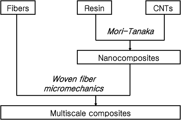
Schematic of modelling for nano- and multiscale composites
Micromechanics for nanocomposites
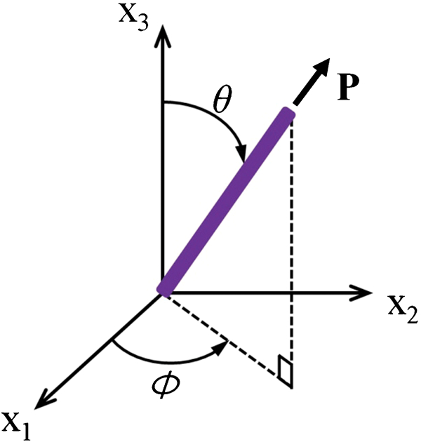
The orientation of an individual, rigid CNT in 3D space, as depicted in Fig. 2, is defined by a unit vector 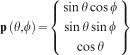
 as
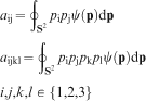
as
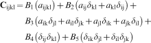


 , C, and Cm are the stiffness tensors of the unidirectional composites, filler and matrix respectively; Vf and Vm are the filler and matrix volume fractions respectively;
To validate the code of the model for nanocomposites (Mori–Tanaka model), the simulation results were compared with the reliable experimental measurements of Young's modulus presented in Refs. 14 and 39–41. The experiments in Refs. 39–41 include different types of CNTs (double walled and multiwalled) manufactured by different companies as reinforcements. Polyvinyl alcohol (PVA) was used as matrix in the experiments. Sonication and casting were used to make their PVA/multiwalled nanotube (MWNT) nanocomposites. In the simulation, the Young's modulus of MWNTs was 800 GPa,14 and the Young's modulus and Poisson's ratio of PVA were 1·9 GPa14, 39 and 0·3340 respectively. The comparison results are shown in Fig. 3. The distributed experimental data in the figure came from different MWNTs and manufacturing methods in their experiments. We conclude that, even with the spread of experimental data, the theoretical bounds capture the entire range of measured values, which suggests the validity of the micromechanics model analysis in estimating the properties of nanocomposites.
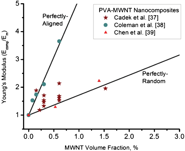
Comparison of result of Mori–Tanaka model with experimental results in Refs. 14 and 39–41 (Ecomp and Em denote Young's moduli of composites and PVA matrix respectively)
Once the stiffness tensor for the nanocomposite is obtained from equation (3), the Young's moduli, Poisson's ratios and shear moduli can be readily obtained using standard mechanics formulations (see e.g. Jones42 and Kim43).
Mechanical properties of CNTs
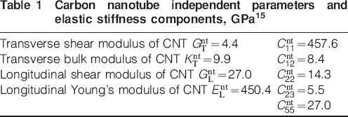
In this simulation, SWNTs were used, each with a diameter of 2 nm and a length of 500 nm. The five independent components of the transversely isotropic stiffness tensor Cnt for the CNTs used in this research are compiled in Table 1, as provided by Odegard et al.15
Carbon nanotube independent parameters and elastic stiffness components, GPa15
Woven fibre micromechanics for multiscale composites
Several micromechanic models for woven fibre composites have been proposed.30,31,44–46 In this work, a woven fibre micromechanics model called MESOTEX32, 33 is selected because of its ability to handle a wide range of architectural geometries for woven fibre composites. Classical laminate theory47, 48 is employed in the construction of the woven fibre micromechanics model to allow consideration for strand undulations and allowances to integrate the geometrical and mechanical parameters of each constituent (resin, fill and warp strands).
The stiffness matrix [A] for a repeating unit cell can be expressed as a summation of the stiffness matrixes of fill strand (tow), warp strand (tow) and polymer resin33
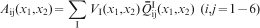
 is the transformed stiffness matrix for the ‘I’ element, and the superscript ‘I’ denotes either the fill strand F, the warp strand W or the matrix M. VI is the volume fraction of the ‘I’ element in the slice in a repeating unit cell. Equation (11) is the expression of the classical thin laminate theory of fill and warp strands and the matrix at each point (x1 and x2).32
The
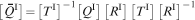
 , a 6×6 stiffness matrix transformed with respect to a global coordinate system, can be obtained for the ‘I’ element as33
 is the Reuter matrix, and
 is the transformation matrix taken to rotate the stiffness matrix expressed in its principal reference frame into the global reference frame accounting for the spatial dependence of the stiffness due to undulations of the fabric.
In this work, the Mori–Tanaka model14, 15, 31, 49 is used to obtain the stiffness matrixes
 for the fill and warp strands. The fill and warp strands are considered, locally, to be unidirectional continuous fibre composites whose principal direction corresponds to the direction of the weave, which is dependent on the fibre direction and undulation.
To obtain the transformation matrix
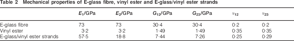
 (see Scida et al.33), the geometry information of the fill and warp strands must be considered, where in this simulation we select a plain woven fabric. The geometry information of the strands includes orientation and local off axis angles.33 The off axis angles are obtained using the undulation of the strands Hf, which is expressed as the undulation along the x1 axis of the median fibre of the fill strands as
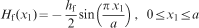
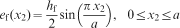
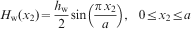
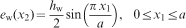
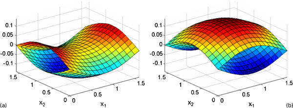
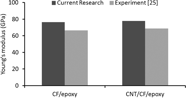
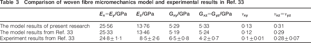
Figure 4 shows computer generated fill and wrap strands using equations (13)–(16). To validate the woven fibre micromechanics model obtained from Ref. 33 and used in this study, the simulation results of E-glass/vinyl ester composites were compared with the experimental and simulation data reported in Ref. 33. Table 2 shows the mechanical properties of E-glass fibre, vinyl ester matrix and E-glass/vinyl ester strands used in Ref. 33 and employed in this simulation for comparison. For the geometry parameters for the plain woven composites, 0·6, 0·05 and 0·1 mm were used for strand width, strand thickness and unit cell thickness respectively. Table 3 presents the results from this work and from Ref. 33 for comparison, showing that the woven fibre micromechanics was successfully employed in this work. In addition, the numerical model for multiscale composites, consisting of the Mori–Tanaka model and woven fibre micromechanics, was compared with the experimental data in Ref. 27. Figure 5 illustrates the comparison results of Young's modulus, showing there is ∼12% discrepancy between current theoretical simulation results and experimental results in Ref. 27. The mechanical properties of multiscale composites are affected by several factors, such as the constituent material's properties, the width and thickness of the fibre strand and the aspect ratios of CNTs. Although IM7 carbon fibres were used, the fabric weave and the CNTs used were different from those in our research. These differences may have resulted in the discrepancies observed between the simulated and experimental results. As such, the simulation result of the current work may be assumed to be in reasonable agreement with the experimental data in Ref. 27. For the data of CNT/CF/epoxy in Fig. 5, 5 vol.-% data was used for the simulation, but in Ref. 27, the volume fraction of CNT was not specified.
a fill strand; b warp strand
Simulation results of current research and experimental data from Ref. 27
Mechanical properties of E-glass fibre, vinyl ester and E-glass
Comparison of woven fibre micromechanics model and experimental results in Ref. 33
Fibre volume fraction of woven fibre composites
The fibre volume fraction in the composite system is determined by the strand volume fraction as a function of the entire composite structure and the fibre volume fraction within the strands. The strand volume fraction is obtained using the strand undulation within the repeating unit cell and the associated geometrical parameters, such as strand width and thickness (refer to Figs. 4 and 6). The fibre volume fraction is thus expressed as32

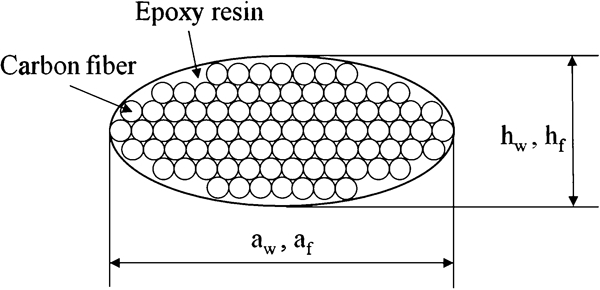
Cross-section of fill and warp strands
Results and discussion
Two extreme cases for the nanocomposite structure were investigated in the present work: unidirectional alignment of the CNTs along the x1 axis and a fully isotropic orientation state (i.e. a uniform random orientation). The aim of considering the two extreme cases was to capture some general trends and attempt to provide bounding conditions for the expected behaviour of structures for nanotube orientation conditions that fall between perfectly aligned and isotropic. It is speculated that the actual orientation state of the CNTs using traditional fabrication methods will tend toward an isotropic state (see e.g. Fig. 2 in Kim et al.50). Nonetheless, the actual orientation of the nanotubes is highly dependent on the processing conditions, and it is unclear how that information may be known a priori using classical fibre collision models (see e.g. Fan and Advani52). For multiscale composites, two aligned cases, aligned along the x1 and x3 axes, and an isotropic orientation case were studied.
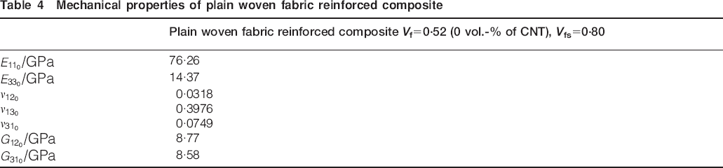
The properties of Epon 862 epoxy polymer were used as isotropic matrix for simulation. The Young's modulus and Poisson's ratio of the polymer are 2·36 GPa and 0·33 respectively. The Young's modulus was obtained via an in-house experimental tensile test, and the Poisson's ratio was obtained from Refs. 47 and 48. The properties of IM7 carbon fibre were used as fibre reinforcement, where the fibre was assumed isotropic with a Young's modulus of 276 GPa and a Poisson's ratio of 0·2.47, 48 Table 4 shows the mechanical properties of the plain woven fabric reinforced composite with no CNTs, as obtained from equation (11). These values will serve as the baseline for further comparisons as the values from Table 4 are for a common industrial system without CNTs. It is worthwhile to note that due to the orthotropic nature of the woven fabric composite,
 ,
,
 ,
,
 ,
,
 and
and
 are respectively the same as
 ,
,
 ,
,
 ,
,
 and
and
 .
.
Mechanical properties of plain woven fabric reinforced composite
Mechanical properties of nanocomposites with respect to CNT concentration
Even though the mechanical properties of CNT/polymer composites have been predicted in several papers,14–16 it is worthwhile to show the predicted properties of nanocomposites here for comparison with the predicted properties of multiscale composites shown in the section on ‘Effects of CNT concentration on mechanical properties of multiscale composites with respect to CNT concentration’. Solutions of equation (3) were obtained for a nanocomposite composed of the CNTs listed in Table 1 and the Epon 862 resin. Results are given in Fig. 7 for stiffness components from the resulting stiffness tensor as a function of volume fraction. The results in Fig. 7a for Young's modulus show that, as expected, Young's modulus increases as CNT loading increases. E11 (45·7 GPa at 10 vol.-%) is higher than E22 and E33 (2·9 GPa at 10 vol.-%) in the x1 axis aligned nanocomposites. In this case, the properties in the 22 and 33 directions are similar to the property of the polymer (Em), as the CNTs aligned in the longitudinal direction make limited contributions in the transverse direction. The Young's moduli of randomly orientated nanocomposites lie between E11 and E22 of the aligned nanocomposites, which indicates some contribution from the CNT inclusions. Table 5 shows the mechanical properties of aligned CNTs and randomly orientated CNTs without polymer matrix (volume fraction of CNT = 1). The properties in Table 5 were obtained using data in Table 1. The mechanical properties of CNTs aligned along the x1 axis given in Table 5 show that E11 is larger than E22 and E33. The Young's modulus of randomly orientated CNTs is greater than E22 but less than E11 values from CNTs aligned along the x1 axis. These properties of CNTs are accumulated in nanocomposites with the increase in CNT loading. This explains the results shown in Fig. 7a.
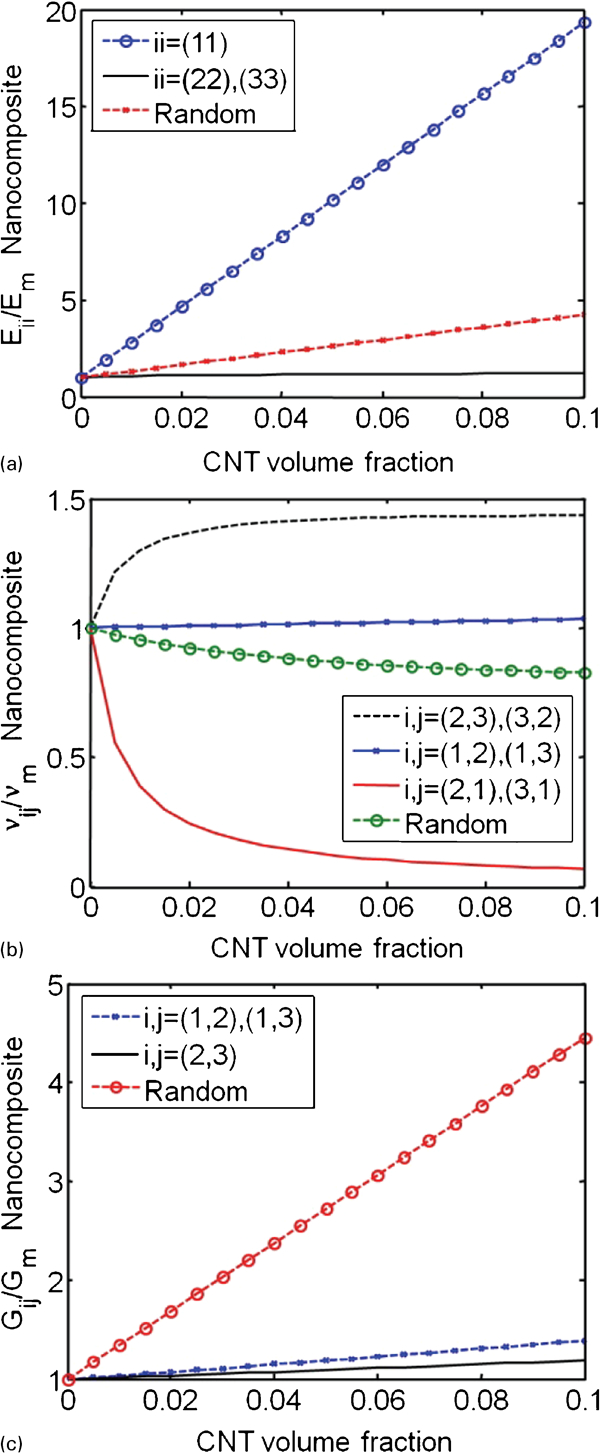
a Young's modulus along x1 axis; b Young's modulus along x2 axis; c Young's modulus along x3 axis
Mechanical properties of aligned CNTs and randomly oriented CNTs without polymer matrix (volume fraction of CNTs = 1)
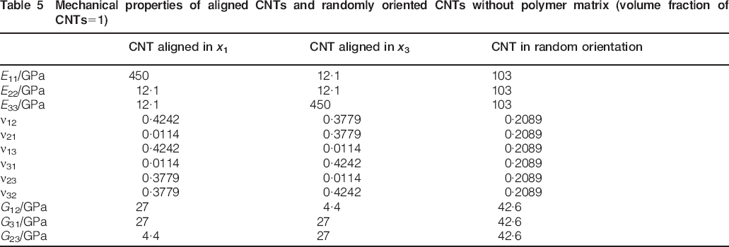
Figure 7b shows the Poisson's ratios of the aligned nanocomposites along the x1 axis and randomly oriented nanocomposites. In Fig. 7b, νm represents the Poisson's ratio of the isotropic resin matrix. Interestingly, ν21 and ν31 of the aligned composites along the x1 axis decrease with an increase in CNT volume fraction. Within the CNT dominated regime, CNT stiffness affects the composite properties more than matrix stiffness does. Thus, as the CNT content increases, the Poisson's ratios of the composite approach those of a CNT specimen listed in Table 5 (CNT aligned in x1).53 Engineers can use this phenomenon to reduce Poisson's ratio in a certain orientation when designing composites. The Poisson's ratios (ν23, ν32, ν21 and ν31) increase and decrease significantly within 3 vol.-% of CNTs. The Poisson's ratio of randomly oriented nanocomposites slightly decreases with an increase in CNT loading. Since ν12, ν13, ν23 and ν32 are higher than the Poisson's ratio of the matrix (0·33), as shown in the properties of CNT aligned in x1 in Table 5, the Poisson's ratios increase with the increase in CNT volume fraction. The Poisson's ratio in Fig. 7b, however, does not simply follow the values in Table 5. For the x1 axis aligned CNT in Table 5, ν12 and ν13 have higher values than ν23 and ν32, but in Fig. 7b, ν23 and ν32 of the nanocomposites are higher than ν12 and ν13. The tensile moduli E11, E22 and E33 are related to the extensional response to an individual applied stress σ1, σ2 and σ3 respectively. However, the Poisson's ratios are related to the coupling between dissimilar normal stresses and normal strains (extension–extension coupling).42 This seems why the Poisson's ratios have a slightly different trend, as shown in Table 5.
Figure 7c shows the shear modulus of the aligned nanocomposites along the x1 axis and randomly oriented nanocomposites. Gm is the shear modulus of the epoxy resin matrix. For the shear modulus depicted in Fig. 7c, the randomly oriented composite yields a higher value than the aligned composites, and as the packing density increases, this trend becomes more obvious. This may be attributed to the lack of directionality in the reinforcing effect obtained from the randomly oriented CNTs as opposed to the aligned CNTs. The shear moduli G12, G23 and G31 are in the diagonal elements of the stiffness matrix and related to the shear stress in the same plane42 such that the shear moduli seem to have the same trend as the shear moduli of the x1 axis aligned CNT and randomly oriented CNTs in Table 5. The shear moduli of randomly oriented composites have higher values than any other shear modulus in Table 5.
Effects of CNT concentration on mechanical properties of multiscale composites with respect to CNT concentration
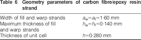
The geometric parameters of the IM7 carbon fibre/epoxy resin strand (tow) are defined in Table 6 and Fig. 6. The width and thickness parameters of the strands were measured by investigating the cross-section of the carbon fibre/epoxy composite using an optical microscope (Olympus BX40 and analySIS imager). Assuming that the fibre volume fraction in a multiscale composite is 52%,24 the fibre volume fraction of the strands is readily calculated using equation (17) to be 80%. The mechanical properties of the carbon fibre/epoxy resin strand, which is a unidirectional continuous fibre composite, are obtained using the Mori–Tanaka model14, 15, 31, 49 for a unidirectional stiffness tensor.
Geometry parameters of carbon fibre/epoxy resin strand
In the manufacturing process of fibre reinforced composites, such as hand lay up or vacuum assisted resin transfer molding (VaRTM), the fibre strands (or tows) are tightly packed under vacuum, so there are very few, if any, CNTs that can infuse within the fabric strands, and the CNTs tend to remain within the resin that does not wet the tow. Therefore, we assumed that there were no CNTs within the strands, and the pure resin properties were used to predict the mechanical properties of the fibre strand composites in the simulation of multiscale composites. The nanocomposites’ mechanical properties from equation (3) were used for the matrix properties outside of the strands in the simulation. The simulation results of the multiscale composite using equation (11) in terms of the volume fraction of CNTs are shown in Figs. 8–10.
 ,
,
 and
and
 , where i, j = 1,2,3, in the figures represent respectively Young's moduli, Poisson's ratios and shear moduli of the fibre/epoxy composite without CNTs, which are shown in Table 4.
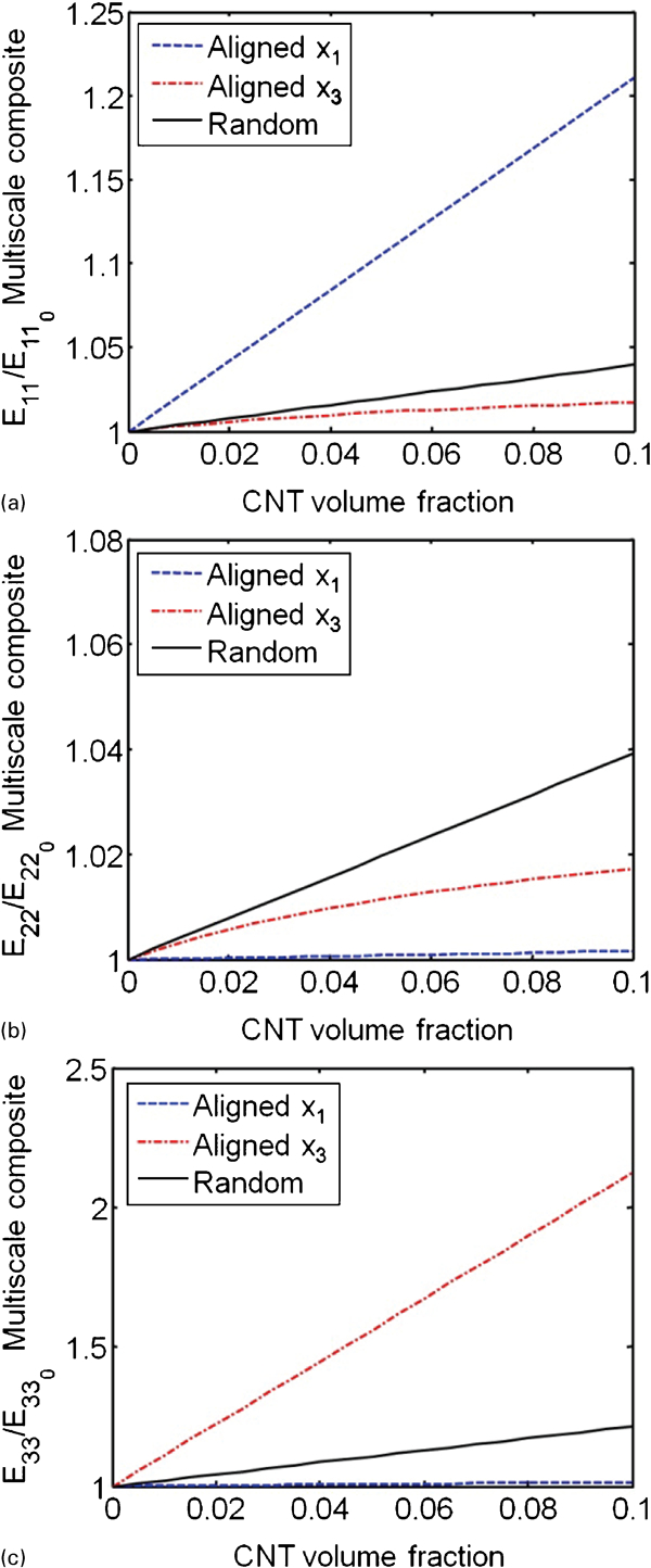
a Young's modulus along x1 axis; b Young's modulus along x2 axis; c Young's modulus along x3 axis
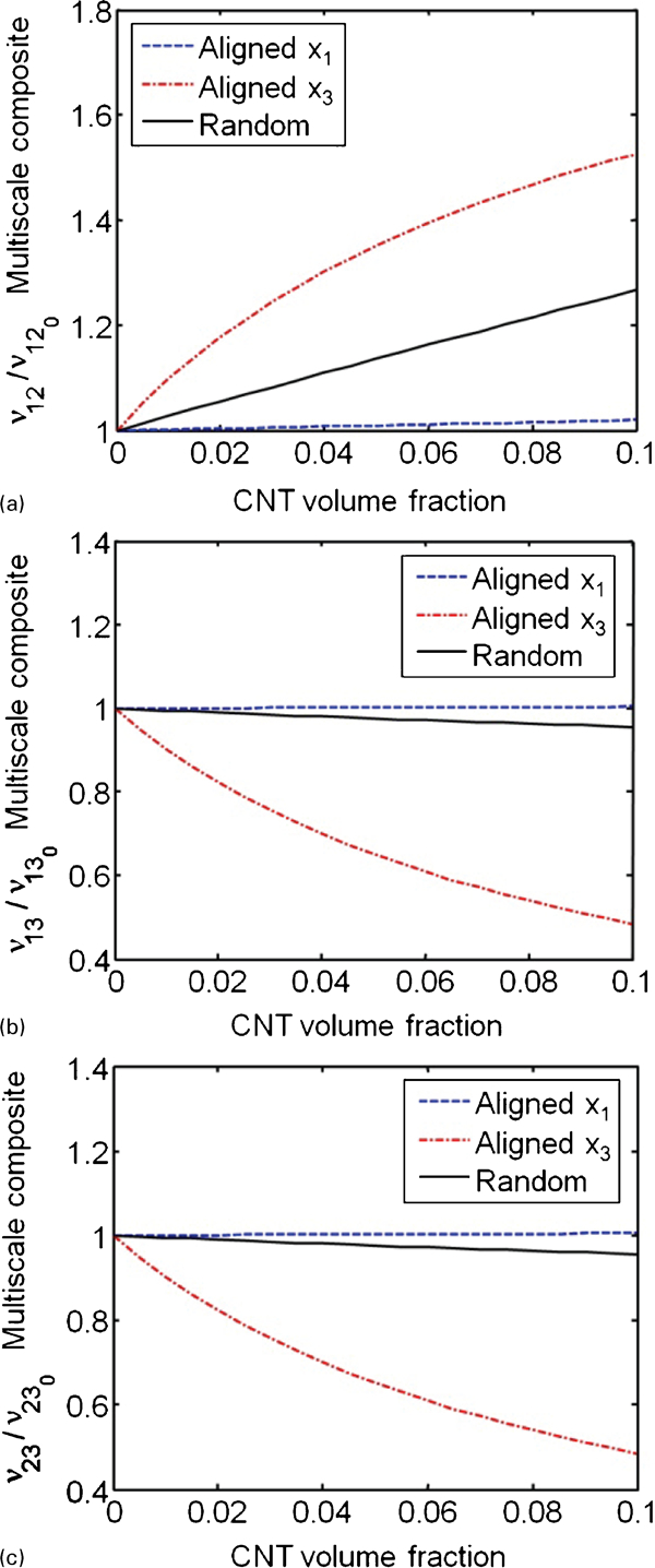
a Poisson's ratio in x–y plane (ν12); b Poisson's ratio in x–z plane (ν13); c Poisson's ratio in y–z plane (ν23)
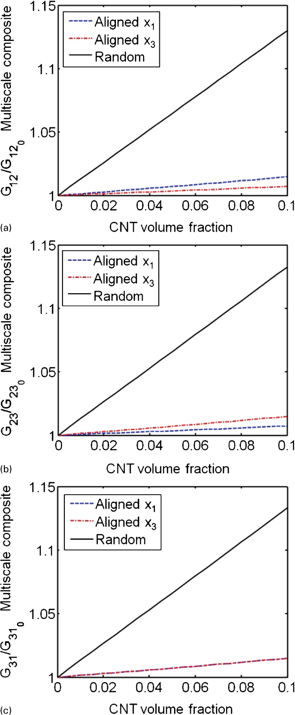
a shear modulus in x1–x2 plane; b shear modulus in x2–x3 plane; c shear modulus in x3–x1 plane
Figure 8 shows the effect of CNT content on the Young's modulus of multiscale composites. Figure 8a–c depicts the variations of aligned (x1 and x3) and randomly oriented CNTs with volume fraction. Figure 8a implies that the values of E11 are higher in the aligned x1 composites than the others. This is replicated in the values of E33, with the aligned x3 multiscale composite yielding the highest values (Fig. 8c). It is worthwhile to note that the addition of CNTs has the greatest effect on the out-of-plane structural response, where 5% loading (CNT volume fraction 0·05) with random (isotropic) orientation results in an improvement of >2% of the in-plane modulus (<1·02 of
 and
and
 in Fig. 8a and b), whereas the out of plane modulus increases by nearly 10% (Fig. 8c). The trends for the aligned composite are even more drastic where the 5% CNT loading aligned in the x1 direction results in an 11% increase in the E11 modulus (Fig. 8a), whereas the 5% CNT loading aligned in the x3 direction would result in an improvement of E33 of nearly 56% (Fig. 8c). In both cases, the transverse Young's modulus E22 shown in Fig. 8b is less drastic where the randomly oriented multiscale composites experience the greatest improvements.
In Fig. 9a, all the Poisson's ratios of ν12 increase with the increase in CNT loading in multiscale composites. In multiscale composites with CNTs aligned along the x3 axis, ν12 increased from 0·0318 at 0 vol.-% of CNT (see Table 4) to 0·0485 at 10 vol.-% of CNTs, that is, the ratio of
 increased from 1 to 1·53. For the x3 axis aligned multiscale composites in Fig. 9b and c, the Poisson's ratios associated with the out of plane direction (x3), i.e. ν13 and ν23, decrease significantly with the increase in CNT loading, like ν21 and ν31 of the x1 axis aligned nanocomposites in Fig. 7b. Figure 10 shows the effect of CNT content on the shear modulus of multiscale composites. Figure 10a–c depicts the variations of aligned (x1 and x3) and randomly oriented CNTs with volume fraction. They show that the randomly oriented composites generated higher values than the two aligned composites in all three planes. As explained in the section on ‘Mechanical properties of nanocomposites with respect to CNT concentration’, randomly oriented CNTs can support shear stresses in any direction. In Fig. 10a, the shear modulus G12 of the multiscale composites with CNTs aligned along the x1 axis is higher than that of the multiscale composites with CNTs aligned along the x3 axis. However, the shear modulus G23 in Fig. 10b experiences reverse behaviour between the multiscale composites with aligned CNTs along the x1 axis and aligned CNTs along the x3 axis. Regarding G31 in Fig. 10c, the shear moduli of the multiscale composites with aligned CNTs along the x1 axis and aligned CNTs along the x3 axis are the same. These results suggest that when designing multiscale composites for shear modulus, the CNT reinforcements should be random, not aligned.
Effect of CNT aspect ratio on mechanical properties
To evaluate the effect of the aspect ratio of CNTs on the mechanical properties of composites, unidirectional nanocomposites and multiscale composites with discontinuous and continuous CNTs were studied. Figure 11 shows the comparison of Young's modulus E11 of nano- and multiscale composites with continuous and discontinuous CNTs.
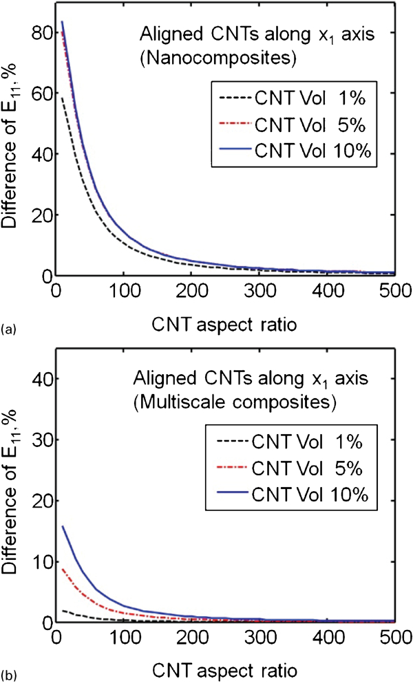
a longitudinal modulus (E11) of unidirectional nanocomposites with continuous and discontinuous CNTs; b longitudinal modulus (E11) of unidirectional multiscale composites with continuous and discontinuous CNTs
If a 5% error is allowed, the 5% difference in longitudinal modulus between continuous and discontinuous CNT nanocomposites occurs at the aspect ratio of ∼200 for unidirectional composites (Fig. 11a), whereas the 5% difference occurs at the aspect ratio of ∼70 for multiscale composites (Fig. 11b). Therefore, it can be concluded that the CNT aspect ratio has a stronger influence on the mechanical properties of nanocomposites than multiscale composites. For nanocomposites, it may be inferred that the mechanical properties of nanocomposites are not significantly affected by the CNT aspect ratio above ∼200.
Fibre/epoxy strands and CNTs/fibre/epoxy strands
As discussed previously, it was assumed that CNTs do not filtrate into fibre strands under high vacuum during the manufacturing process, such as VARTM and hand lay up, leaving neat epoxy resin in the fibre strands. However, if SWNTs, smaller diameter CNTs, with low aspect ratio (short SWNTs), are used to make multiscale composites, SWNTs may get into the fibre strands during the manufacturing process. As such, this work simulated two types of multiscale composites. The first was a multiscale composite without CNTs in the fibre strands (as discussed in the preceding section and shown in Fig. 12a); the other is a multiscale composite with randomly oriented CNTs in the fibre strands (Fig. 12b). For both composites, it was assumed that the CNTs were randomly oriented in the matrix region outside of the fibre tows.
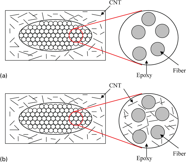
Multiscale composites a without and b with CNTs in fibre strands
Using equations (3) and (11), a comparison was made between the two systems, and the material properties are presented in Fig. 13. In Fig. 13a and b, it is quite clear that there is a significant difference in the Young's moduli of the multiscale composites between the two systems. For a 5% loading of CNTs in Fig. 13a, multiscale composites with CNTs in the fibre strands have an increase in the tensile moduli of nearly 7%, whereas the multiscale composite without CNTs in the fibre strands experiences an increase of only 2%. The response of a 5% CNT loading in the through thickness direction (x3) in Fig. 13b is even more drastic, where the tensile moduli increase by nearly 76·4% for the system with CNTs in the fibre strands versus an increase of only 10·8% in the case without CNTs in the strands. Drastic differences are observed between the two systems for the Poisson's ratios ν12 and ν13 and the shear modulus G12, as observed in Fig. 13c–e. Generally, the composites that have CNTs in the fibre strands generate more desirable mechanical properties than the composites that have no CNTs in the fibre strands.
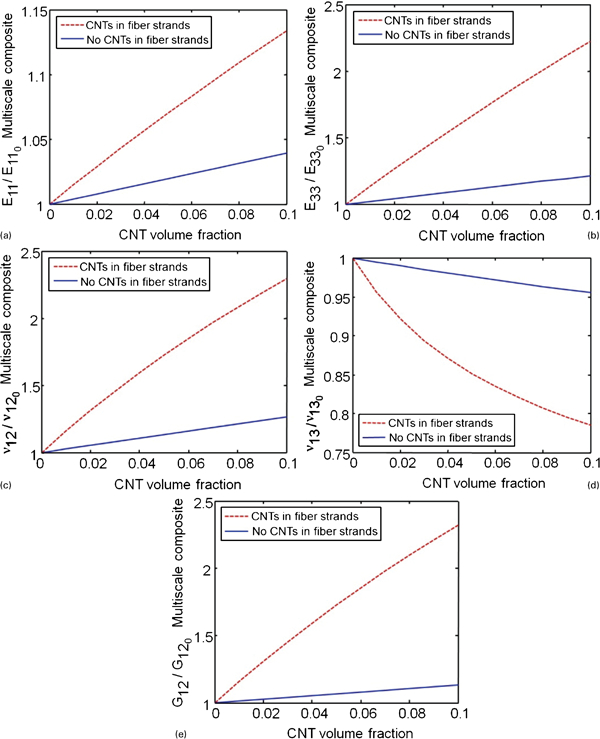
a tensile modulus along x axis; b tensile modulus along z axis; c Poisson's ratio on x–y plane; d Poisson's ratio on x–z plane; e shear modulus on x–y plane
Conclusions
This work investigated the effects of integrating CNTs in nano- and multiscale composites. The simulations were performed by combining dilute micromechanics (the Mori–Tanaka model) and woven fibre micromechanics (MESOTEX). The mechanical properties, namely, Young's modulus, Poisson's ratio and shear modulus, of nano- and multiscale composites were obtained for CNT loadings of up to 10 vol.-%. As expected and also shown in the sections on ‘Mechanical properties of nanocomposites with respect to CNT concentration’ and ‘Effects of CNT concentration on mechanical properties of multiscale composites with respect to CNT concentration’, the Young's moduli and shear moduli increase with the increase in CNT loading, and the rate of increase in these properties is more pronounced in nanocomposites than in multiscale composites. In the case of nanocomposites, some of the Poisson's ratios, such as ν21 and ν23, were significantly changed with <3 vol.-% of CNTs. In the x3 axis aligned multiscale composites, the Poisson's ratios associated with the out-of-plane direction (x3), i.e., ν13 and ν23, decrease significantly with the increase in CNT loading.
The effects of CNT aspect ratio on the mechanical properties of nano- and multiscale composites were also studied. The influence of CNT aspect ratio was stronger in nanocomposites than in multiscale composites. The 5% difference in longitudinal modulus between the continuous and discontinuous CNT nanocomposites occurs at the aspect ratio of ∼200 for unidirectional nanocomposites, whereas the 5% difference occurs at the aspect ratio of 70 for multiscale composites. In addition, the effects of the presence of randomly oriented CNTs in fibre strands were investigated. The results indicate that the composites that have CNTs in the fibre strands have improved mechanical properties as compared to the composites that have no CNTs in the fibre strands. The results reported in this study can be used as a preliminary tool to design CNT based nanocomposites and multiscale composites (e.g. CNT loading, orientation, etc.) such that the desired mechanical properties may be obtained.