
Abstract
Compressive strength reduction due to fibre waviness is a key concern in composite structures. Specimens with fibre misalignments representative of those that can occur at ply drops and resin rich areas in components were manufactured by incorporating either two or 10 discontinuous plies oriented either in 0° (‘longitudinal’) or 90° (‘transverse’). Longitudinal specimens did not fail in compression but failed by delamination initiating at the ply drops. Transverse specimens did not fail directly due to the waviness: specimens with 8° waviness failed at similar stresses and strains as fully aligned specimens, while 30° waviness specimens failed in the aligned plies at a slightly reduced overall stress due to redistribution of load from the less stiff wavy plies. None of the specimens failed directly in compression due to misalignment in the wavy plies, indicating that this is not necessarily the critical failure mechanism, and highlighting the importance of delamination and load redistribution at ply drops.
Keywords
Introduction
Fibre waviness (FW) defects, i.e. angular misalignment of fibres to the nominal direction (defined in the section on ‘Definition of FW’), have been noted for decades. Theoretical models of microbuckling failure in unidirectional (UD) composites identified the fibre misalignment/waviness as a critical governing feature.1, 2 This buckling instability may be initiated from local fibre misalignment,1 which propagates and causes compressive failure via a kink band/microbuckle.2–4 Failure mechanisms during kink band formation were studied either in situ5 or post-failure.6 Kink banding is thought to be initiated by matrix yielding through initial fibre misalignment,7 followed by sudden in-plane propagation and unstable increase in kink band features, with band broadening in the end.6
Most work about waviness effects has focused on the non-linear material behaviour and strength reduction.8–18 Daniel et al.19 reported that thick composites under compression loading failed by shear yielding in the matrix, induced by pre-existing fibre misalignment. Leong et al.20 showed both compression and delamination failure modes in the wrinkled face sheet of a wind turbine blade sandwich structure. This study aims to provide practical understanding of the effect of waviness to facilitate development of a comprehensive theory for failure and hence to benefit composites’ design. Two newly designed techniques21 for generating out-of-plane FW were therefore employed, and the sequence of failure modes including the damage initiating mechanism was studied. The effect of the designed in waviness on strength under compressive loading was quantified.
Definition of FW
The out-of-plane waviness of a whole ply in a flat laminate is defined by the wavelength λ (the maximum span of wavy fibres referenced to the nominal fibre direction, i.e. the length of the wavy region), amplitude δ (the maximum height of wavy fibres to the nominal fibre direction) and misalignment angle θ (the angle of wavy fibres inclined to the nominal fibre direction), as shown in Fig. 1. Wave severity (%) is expressed by δ/λ. As suggested by theoretical models for the effect of FW on composite strength, the maximum misalignment angle θmax is critical.
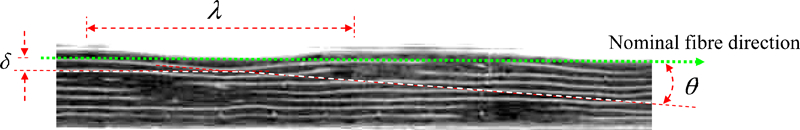
Photograph of out-of-plane waviness in resin transfer moulding component, adapted from Ref. 22, showing waviness length λ, amplitude δ and misalignment angle θ
Specimen preparation and compression test procedure
Materials used were carbon reinforced prepregs (AS4/8552) from Hexcel Composites. Nominal cured ply thickness and calculated fibre volume fraction are 0·13 mm and 57·42% respectively. An examination of some defects within commercial components was used to design a testpiece that combined the use of a conventional laminate compressive test rig with a suitable level of misaligned fibres. The testpiece design is believed to capture the features seen in practical defects, although it cannot be guaranteed that the strength reductions seen in the testpieces will be the same as those seen in defective components. Figure 2 shows a schematic of the fabricated test specimens using discontinuous layers that are rotationally symmetric to create a central waviness zone with a maximum misalignment angle of either 8 or 30°. One method uses longitudinal discontinuous plies, representing the effect of waviness produced at ply drops as shown in Fig. 2a, while the other uses transverse plies to form similar FW, but without the severe discontinuity of the longitudinal ply drops, as shown in Fig. 2b. For the constant thickness longitudinal ply drop (CLPD) case, a two-ply 150×75 mm 0° strip of prepreg was aligned and laid on a six-ply 150×150 mm laminate at one end. Two 150×150 mm 0° plies were added, and vacuum debulking was applied after every ply to reduce air trapped within the wavy region. A further two 150×75 mm 0° sheets were aligned at the other end of the laminate. This gives a gap between the discontinuous plies. Six more 0° 150×150 mm plies were added, and vacuum debulking was again applied after every ply. The laminate was then ready for vacuum bagging and autoclave curing. A caul plate was used on top. An equivalent method was used for the constant thickness transverse ply drop (CTPD) case.
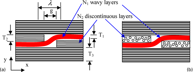
Cross-sectional views along nominal fibre direction (x axis) of laminates. Discontinuous layers used to generate waviness are a along nominal fibre direction and b transverse to nominal fibre direction. N1 and N2 are numbers of plies of wavy and discontinuous layers. T1, T2 and T3 are thickness of wavy layers, discontinuous layers and base layers respectively. g is gap between the two discontinuous layers. λ is length of wavy region
The cured laminate was end tabbed with 2 mm thick woven glass epoxy laminates (CYCOM 977-2 prepregs) using Redux 810 adhesive and finally machined to 90×10 mm length×width, schematically shown in Fig. 3.
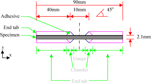
Cross-section of compression test specimen, showing end tabs bonding onto top and bottom surfaces of UD laminate; fibres are along x axis; failure regions are divided into gauge section, chamfer areas and end tab regions
Compression tests, using the fixture originally developed by Haberle and Matthews,23 were performed using a Zwick testing machine (100 kN capacity) at ambient temperature. Compressive strain was measured using an Imetrum non-contact video gauge24 comprising a 15 Hz video camera and a telecentric lens. All samples were loaded to failure under displacement control at a rate of 1 mm min−1 crosshead speed. Any samples with premature failures at the tab regions were discarded as invalid.
Unidirectional laminates were used to determine the baseline compressive strength. In total, 25 samples were tested. Samples were expected to fail at the end of the gauge section (see Fig. 3) due to the effect of the stress concentration. Therefore, 21 samples showing damage in the end tab regions were considered as invalid. The remaining four samples then gave an average value of 1539 MPa for the baseline.
Failure mechanisms under compression loading
In the current study, high speed photography was used to observe both the initiation and propagation of failure at a sufficient frequency to observe the sequence of events. The designed waviness was uniform across the specimen width, and so, an edge view was representative.
Sequence of failure modes: CLPD fabricated specimens
Careful examination of the video recording and the damage state of the tested samples indicates the sequence of failure modes for specimens with longitudinal discontinuous plies as follows: delamination initiates at the ply drops, followed by compressive fracture of the straight layers due to the loss of global stability, as shown in Figs. 4 and 5 for 8° waviness and in Fig. 6 for 30° waviness. Figure 4 shows an evolution of failure mechanisms using a series of high speed photographs for the 8° waviness case. Delamination occurred between the wavy layer and the discontinuous layers and propagated at high speed (>360 m s−1). The straight outer layers subsequently underwent bending due to the loss of stability and antisymmetry of the wavy layer. The bending curvature increased with compressive loading. At 675 μs, the wavy layer was compressively fractured, subsequently reducing the bending curvature. After a further 8·33 μs, compressive fracture of the straight layers occurred, leading to catastrophic failure. In the whole failure process, delamination was the initiation mechanism, followed by subsequent compressive failure in the primary elements with extensive delamination. Therefore, the stress concentration at the end of the ply drops induced interlaminar failure (normal and shear), rather than causing failure due to the introduced additional compressive stresses.
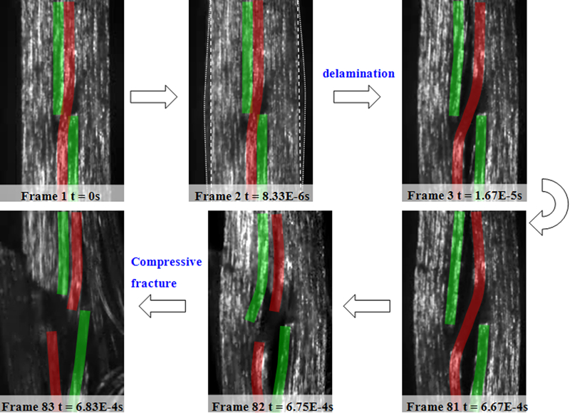
Evolution of failure mechanisms: from delamination at ply drops to compressive fracture through thickness of [06/FW2/02/06] using 120 000 frames/s
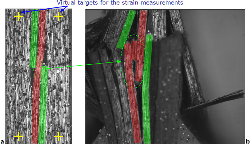
Video images of failure modes of [06/FW2/02/06] sample: wavy layer and discontinuous layers are highlighted
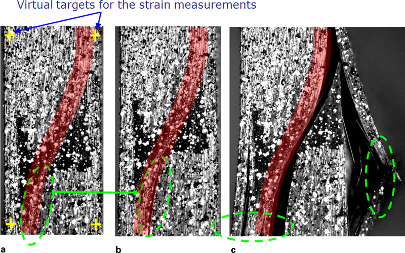
Video images of failure modes of [02/FW2/010/02] sample
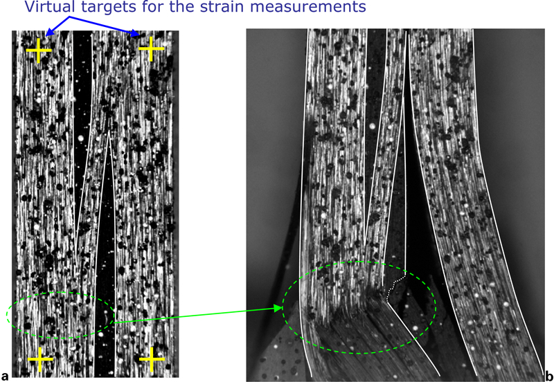
The measured loads and strains at catastrophic failure are shown in Table 1. The strains were measured in the straight plies by placing virtual targets along the fibre direction in the Imetrum Video Gauge software24 as shown in Figs. 5a and 6a. Via the software, the strains were determined from the relative displacements between the virtual targets (contrasting gauge marks) in the video clip. The four virtual targets gave two strain readings, which were then averaged to determine the overall compressive strain in the straight plies at the gauge section. In order to enhance the contrast for tracking the virtual targets, the surface in the gauge section was painted a white speckle pattern. In order to interpret ply stresses at failure, some approximate calculations were carried out based on linear elastic laminate theory. The ply stresses were estimated at two sections, across a section at the end of the gauge length and at the centreline section (where the θmax is). The approach is given in Appendix.
Compression results for specimens with longitudinal discontinuous plies (% coefficients of variation): five specimens for each lay-up were tested
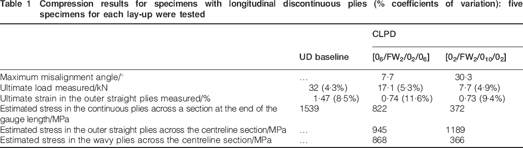
The large reductions in stress in the outer straight plies at the centreline section for the CLPD specimens show that the specimens failed prematurely due to the defects. It is demonstrated by the high speed photographs in Fig. 4 that the failure occurred by delamination, leading to instability of the outer straight plies, causing early failure before reaching the baseline strength of 1539 MPa. In other words, the failure occurred due to the stress concentration inducing delamination rather than by the additional compressive stress due to the stress concentration.
Sequence of failure modes: CTPD fabricated specimens
Figure 7 shows the evolution of failure in a series of high speed photographs for a sample with two transverse discontinuous plies (8° waviness). These images indicate delamination between the transverse discontinuous plies and the outer straight layer at 2·5 μs, followed by a downwards vertical movement (maybe due to microbuckling at the end of the gauge section outside the view) and further delamination after a further 5 μs, leading to catastrophic failure. Figure 8 presents photographs taken by a 15 Hz camera for another sample, showing that the catastrophic failure occurred by compressive fracture through the thickness at the end of the gauge section, with delamination at the same interface as that shown by the high speed photographs in Fig. 7. Note that delamination did not occur in the wavy plies where there is higher interlaminar shear, and the indications are that it initiated from the compressive fracture at the tab rather than due to the waviness.
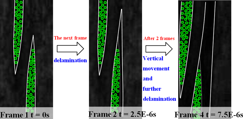
Evolution of failure mechanisms: from delamination at waviness region to compressive fracture through thickness of [06/FW2/902/06] using 400 000 frames/s
Video images of failure modes of [06/FW2/902/06] sample
Specimens with 10 transverse discontinuous plies (29° waviness) failed by kinking in the straight outer plies, followed by an angled fracture through the thickness, as shown in Fig. 9. Positions of the two straight outer layers were tracked versus time during testing using the Imetrum Video Gauge,24 shown in Fig. 10. It was detected that kinking failure occurred at the fourth and fifth points from the top, corresponding to the centre section of the gauge section.
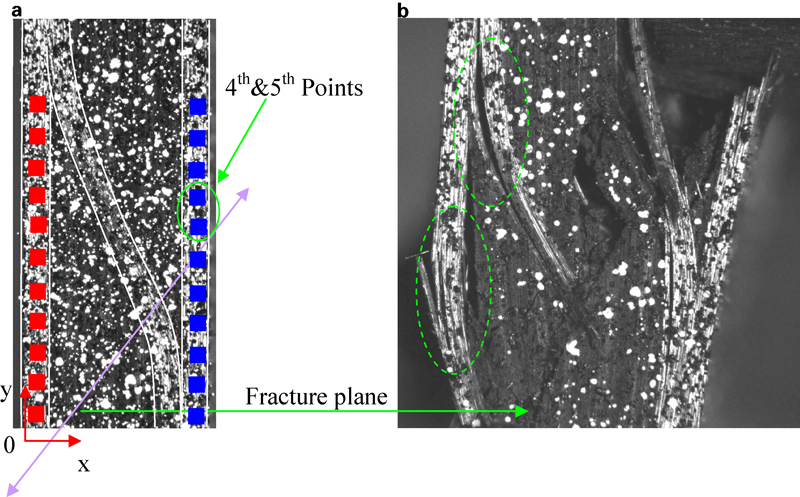
Video images of failure modes of [02/FW2/9010/02] sample
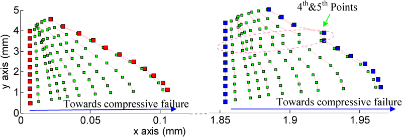
Out-of-plane displacements of the straight outer layers of [02/FW2/9010/02] sample, evolved during compression loading, referred to coordinate system shown in Fig. 9a
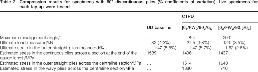
Table 2 shows the test results and estimated ply stresses. The approach for calculating ply stresses is presented in Appendix. The reduced modulus due to off axis misalignment of the wavy plies gives a lower ply stress than in the straight plies, e.g. 1380 MPa compared with 1514 MPa for the 8° waviness case. The outer straight plies at the centreline section also carry a higher load than those straight plies at the ends, 1514 MPa compared with 1496 MPa, due to load shed from the wavy plies. Failure is thought to occur when the straight outer plies adjacent to the waviness reach the critical 0° compressive strength. Table 2 shows that the specimens with two discontinuous plies and 8° waviness failed at a similar stress of 1514 MPa and 1·47% strain to the baseline values of the fully aligned specimens. The specimens with 10 discontinuous plies and 30° waviness also failed in the straight outer plies at an estimated stress at the centreline section (1640 MPa). This is actually higher than the baseline strength, possibly because the latter specimens have a stress concentration at the tabs. This mechanism is shown by Fig. 9, with failure in the outer straight plies at the centreline section and kinking at the fourth and fifth points shown in Fig. 10.
Compression results for specimens with 90° discontinuous plies (% coefficients of variation): five specimens for each lay-up were tested
Conclusions
Despite fibre misalignment of up to 30°, the specimens with longitudinal discontinuous plies did not fail in compression but by delamination due to the stress concentration at the end of the ply drops.
None of the specimens with transverse discontinuous plies failed directly in compression due to misalignment in the wavy plies. Specimens with two discontinuous transverse plies (8° waviness) failed at similar stresses and strains as the fully aligned specimens, implying a negligible effect of FW at low angles. Those with 10 discontinuous transverse plies (30° waviness) failed by kinking in the straight outer plies at a slightly reduced overall stress due to redistribution of load from the less stiff wavy plies, implying that the effect of FW was primarily due to the stiffness reduction in the wavy element.
None of the specimens failed directly in compression due to misalignment in the wavy plies, indicating that this is not necessarily the critical failure mechanism and highlighting the importance of delamination and load redistribution at ply drops.
Footnotes
Acknowledgements
This work was carried out as part of the programme Fibre Waviness Defects in Composite Structures (EP/G015848/1). The authors would like to acknowledge the support of the partners in that programme (University of Cambridge, Dowty Propellers, Vestas Technology UK and Simulayt Ltd) and the financial support from the UK Engineering and Physical Sciences Research Council and Ministry of Defence. Laboratory support from I. Chorley and English editing and proofreading by S. L. Lemanski are also gratefully acknowledged.