
Abstract
Biobased fibres of cellulose acetate butyrate (CAB) and cellulose nanocrystals (CNC) and triethyl citrate (TEC) as plasticiser were prepared by melt spinning. To obtain homogeneous dispersion of CNC, two different dispersion techniques were studied. In the first, the water content of the CNC suspension was reduced and exchanged to ethanol using centrifugation. In the second, the water in the CNC suspension was completely exchanged to ethanol by sol–gel process. Results showed that tensile modulus and tensile strength of the nanocomposite fibres produced with the first technique were lower than CAB–TEC fibres, but the fibres produced by the sol–gel process showed an increase in the tensile modulus and had no decrease in the strength. Optical microscopy of the fibres indicated a few aggregations on the sol–gel prepared materials. The results indicate that the sol–gel process is enhancing the dispersion of CNC and can be a suitable way to prepare nanocomposite fibres.
Keywords
Introduction
Cellulose is the most abundant, renewable, and biodegradable polymer with a hierarchical structure in plants and other biomass sources; it is also synthesised by some bacteria, algae and even animals.1, 2 Nowadays, the forest products industry in USA, Canada, Sweden, Brazil, and some other countries has turned to nanotechnology to develop new applications from cellulose. 3 The term of nanotechnology has been associated with high expectations regarding the potential success to prepare stronger and more functional materials. 4
From cellulosic sources two different types of nanoreinforcements can be achieved, cellulose nanofibres (CNF) and cellulose nanocrystals (CNC). 5 Cellulose nanofibres contain both amorphous and crystalline region of the cellulose and first successful isolation of it was reported in 1983.6, 7 When native cellulose subjected to strong acid hydrolysis, it can be readily hydrolysed to micro or nanocrystalline cellulose. 8 The characteristics of the CNC are dependent on the cellulose origin as well as the isolation conditions. The size can vary between 100 and 1000 nm in length and 4 and 25 nm in diameter, and the elastic modulus can vary between 120 and 140 GPa. 9 Due to its high mechanical strength, high aspect ratio and large surface area (150–250 m2 g–1), CNC has been promoted for the preparation of nanocomposites. 3 One main major challenge in using CNC as reinforcing agent is the difficulty to disperse them in non-polar polymers due to their strong hydrogen bonds, 5 and subsequently strong tendency for aggregation. 10 Different methods such as surface modification, 11 or use of surfactants12, 13 has been applied to overcome this problem, but the advantages of these methods are usually negated because they suppress the reinforcing effect of the crystals.14–16
As the result of environmental awareness of petroleum based polymers, the demand for environmentally friendly materials is dramatically increased. Therefore, the interest for composite materials based on renewable resources, has grown remarkably. 17 Cellulose esters such as cellulose acetate (CA) and cellulose acetate butyrate (CAB), which are produced by esterification of cellulose, can be used as cellulosic matrices in biobased nanocomposite production. 18 So far different studies were carried out regarding nanocomposite preparation of the cellulose esters films using different manufacturing methods,18–21 but only one article, which was produced by electrospinning, could be found in the literature regarding cellulose esters nanocomposite fibres. 22 Since the diameter of the fibres is small and even slight aggregations can cause spin failure, spinning of the nanocomposite fibres renders many challenges. Among different types of spinning methods such as melt spinning, wet spinning and electrospinning, melt spinning is the most common process in the production of continuous thermoplastic fibres. 23 Higher throughput rate of melt spinning compared to other spinning techniques made it an economical and convenient manufacturing method.
In this study, melt spinning was chosen as spinning technique and CAB was chosen as the matrix since it is soluble in ethanol and the results were comparable with previous studies in which other processing techniques were utilised to prepare CAB–CNC nanocomposite films. The main goal was to provide well dispersed CNC in CAB matrix to produce melt spun nanocomposite fibres without using surfactant or surface modification. To achieve the goal, two different techniques were applied to disperse CNC in the CAB matrix and produce nanocomposite fibres. The effect of dispersion methods on mechanical properties of the nanocomposite fibres was the main focus in this study. In a further study, the effect of more CNC content and the effect of fibre drawing on the thermal and mechanical properties of the fibres will be investigated.
Experimental
Materials
Cellulose acetate butyrate was chosen as polymer matrix and was supplied by Eastman Chemical Company (Kingsport, USA). The butyrate content was 46 wt-%, acetyl content 2 wt-% and hydroxyl content 4·8 wt-%. According to the supplier, the CAB used, has a glass transition temperature of 136°C and melting temperature in range of 150–160°C.
VIVAPUR microcrystalline cellulose (MCC) (Weissenborn, Germany) and non-dried dissolving cellulose residue (sludge), obtained from Domsjö Fabriker AB (Örnsköldsvik mill, Sweden) were used as starting material for the preparation of the nanocrystals (CNC) as reinforcing phase. The CNC from MCC was extracted by acid hydrolysis based on the method reported by Bondeson et al., 8 and CNC from sludge was extracted by acid hydrolysis based on the method described by Herrera et al. 9
Environmental friendly plasticiser, triethyl citrate (TEC) C12H20O7 was provided by Fluka Chemie GmbH (Buchs, Switzerland). Triethyl citrate was added to increase the flow by decreasing the melting temperature of the CAB and also to attain toughness to the matrix. Ethanol absolute (99·99%) purchased from VWR, was used as solvent for CAB and for making CNC organogel by sol–gel processing. Sulphuric acid (96%) for acid hydrolysis was also purchased from VWR.
Dispersion method I
The water content of the CNC suspension was reduced and exchanged to ethanol using centrifugation, then the CNC–ethanol mix was premixed with CAB and TEC followed by compounding and dilution to the final composition using extrusion.
Four grams of CNC in aqueous medium were solvent exchanged by four centrifugation steps and redispersed using ultra sonication (Hielscher UP400S, Teltow, Germany) at 70% of maximum power of the sonicator during 1 min to obtain uniform dispersion. The aim of this step was to remove water as much as possible and exchange it to ethanol. However, the bonded water remaining in the surface of the CNC could not be removed by centrifugation. By assuming that just one layer of water molecules was remained on the surface of the CNC, the amount of bond water was roughly calculated by 0·4 g for 4 g CNC (∼10 wt-% of CNC). In initial step to prepare the mixture, 66 g of CAB was dissolved in ethanol to form 15 wt-% solution, then 30 g TEC as well as 4 g CNC in ethanol were added to the mixture. The CAB–TEC–CNC suspension was mixed using magnetic stirring and ultra sonication, cast in polystyrene Petri dishes and dried in the vacuum oven. The dried mixture was pulverised/crushed using a Waring blender and left in the oven overnight to remove remaining solvent. The composition of the dried mixture was 66 wt-% CAB, 30 wt-% TEC and 4 wt-% CNC.
Then the mixture was diluted to the final composition (2 wt-% CNC and 15 wt-% TEC) with CAB using a twin screw extruder (Coperion W&P ZSK 18 MEGAlab, Stuttgart, Germany). The screw speed was 150 rev min–1 and the temperature profile was varied from 140°C at feeding zone to 170°C at the die. The prepared composite was pelletised and stored in the desiccator until the melt spinning process. Same procedure was applied to prepare the reference material of only CAB 85 wt-% and TEC 15 wt-%. Figure 1 shows the schematic view of the entire process.
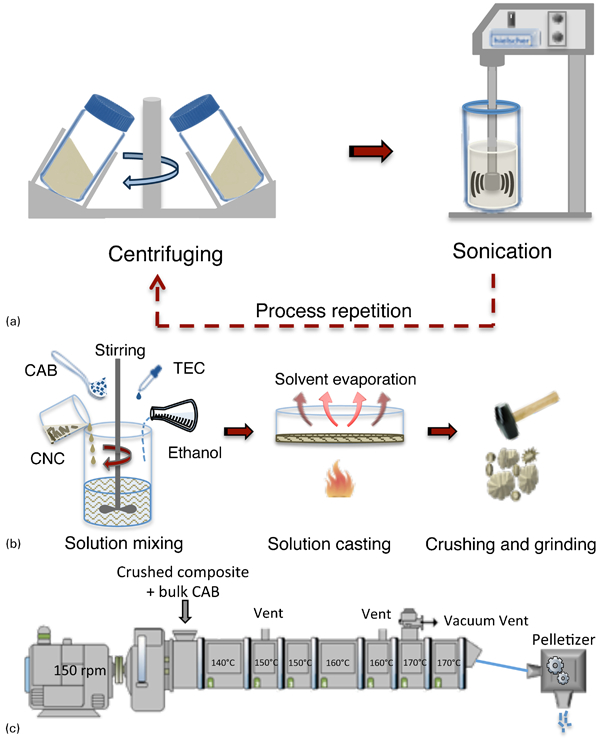
Schematic view of first dispersing technique, a solvent exchange by centrifuging, b solution mixing and c melt compounding using twin screw extruder
Dispersion method II
In the second technique, the water in the CNC suspension was solvent exchanged to ethanol by sol–gel process with the aim to remove the water completely following the procedure described by Siqueira et al. 21 Initially, the suspension of the CNC was diluted to 8·0 mg mL–1 in a 1000 mL beaker and subjected to a brief sonication to disperse the crystals and to remove air. Then, 350 mL ethanol was gently added on top of the CNC suspension to form an organic layer on the top of the aqueous dispersion. This organic layer was gently agitated and exchanged once a day to facilitate the solvent exchange. The mechanically coherent CNC ethanol organogel was formed after 6–7 days. The organogel of nanocrystals was broken by ultra sonication bath for 10 min.
There after dissolved CAB–TEC and the organogel with 2% CNC were mixed, solution cast, dried and pulverised/crushed using similar way to that one described earlier. Same process was applied to prepare CAB–TEC as the reference material. A schematic image of the sol–gel process is presented in Fig. 2.
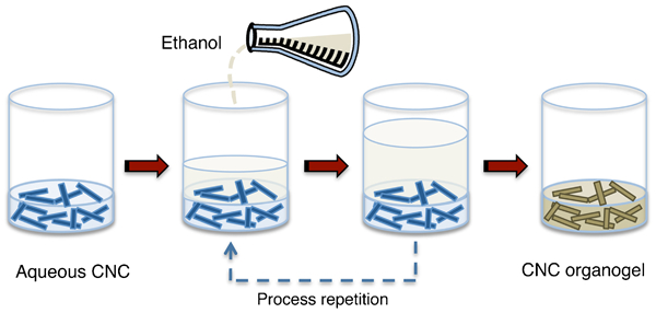
Schematic view of cellulose nanocrystals (CNC) organogel preparation
Melt spinning process
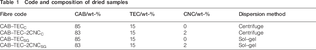
All materials were melt spun to monofilament fibres using a 15 mL twin screw microcompounder, DSM Xplore (Geleen, The Netherlands) at 160°C under argon atmosphere (Fig. 3). A 0·4 mm spinneret was attached to the outlet of the microcompounder to prepare monofilament fibres. The as spun fibres were cooled by air and collected directly on a rotating take-up roll with 50 cm distance from the spinneret and stored in a conditioning chamber prior to tensile testing. The compositions of the produced fibres are summarised in Table 1.
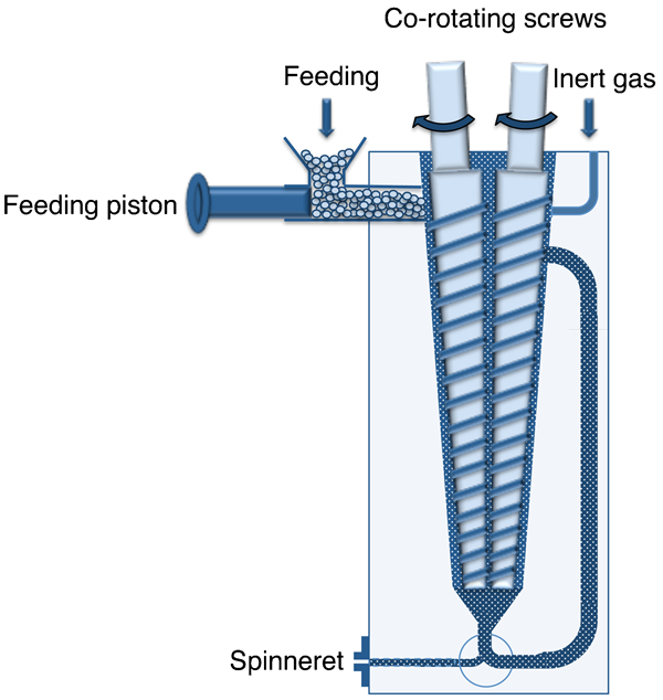
Schematic view of 15 mL twin screw microcompounder (DSM Xplore, The Netherlands)
Code and composition of dried samples
Instrumental analysis
Birefringence
A setup containing two polarising filters, a lamp and a magnetic stirrer was used to study flow birefringence of the CNC suspension. Flow birefringence is a preliminary method, which can be used to prove whether CNC is successfully isolated or not.9, 20, 24–26
Atomic force microscopy (AFM)
To characterise the isolated CNC a Veeco multimode scanning probe with nanoscope V software (Santa Barbara, CA, USA) was utilised. To prepare the samples, a drop of diluted aqueous CNC suspension was deposited on a mica surface and dried at room temperature. The scanning operated in tapping mode and the height and amplitude images were collected.
Scanning electron microscopy (SEM)
A JEOL JSM-6460LV scanning electron microscope (SEM) was used to morphology study of the fibres. The fibres were sputter coated with a gold layer prior to the examination to avoid charging. The acceleration voltage of 15 kV was used.
Optical microscopy (OM)
To acquire optical micrographs of the fibres, a Nikon ECLIPSE MA200 (Tokyo, Japan) optical microscopy with the NIS-Elements BR 3·1 image analysing software equipped with a polarised filter was used. To obtain more details, both transmitted and direct light mode were utilised for the all four produced fibres. In addition, to get more focused images, two nanocomposite fibres (CAB–TEC–2CNCC and CAB–TEC–2CNCSG) were pressed between two microslide glasses to thin films in an oven at 180°C. The films were examined on the microscopy on the same mode.
Tensile testing
To study the mechanical properties of the fibres, a universal testing machine, Tinius-Olsen UTM (Horsham, PA, USA) with a 100 N load cell was used. The tests were conducted at room temperature at a constant speed of 50 mm min–1 with 0·1 N preload and the gauge length of 50 mm. All samples were stored in a conditioning chamber at 23°C and 50% RH prior to testing. The fibres diameter was measured by micrometre for each replication and six replications for each sample were performed and the average values as well as standard deviations were reported. Moreover, statistical analysis based on the ANOVA and Tukey-HSD multiple comparison test was applied to see whether the results are significantly different at 5% significance level.
Results and discussion
Cellulose nanocrystals characterisation
Flow birefringence of produced crystals (Fig. 4) confirms the presence of crystals in the aqueous cellulose suspensions obtained after hydrolysis. As it can be seen the CNC isolated from both sources are showing birefringence and are well dispersed in water.
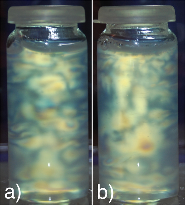
Flow birefringence of cellulose nanocrystals a isolated from MCC and b isolated from sludge
The structure and size distribution of the prepared suspension of crystals were analysed by AFM, as shown in Fig. 5. The height and amplitude showed the presence of well isolated and dispersed crystals in nanometre scale for both sources. Based on the AFM images, the diameter of the crystals was in range of 4–12 nm. To avoid broadening effect and get more accurate measurement, the measurements were made with the help of a software in which the height of the crystals is determined and considered as crystals diameter. Even though different cellulose sources have been used to produce crystals, the AFM results showed that they have similar shape and size. According to earlier studies in our group, these crystals have very similar crystallinity index as well (85·4±4·2% for MCC and 85·8±4·4% for sludge).9, 27
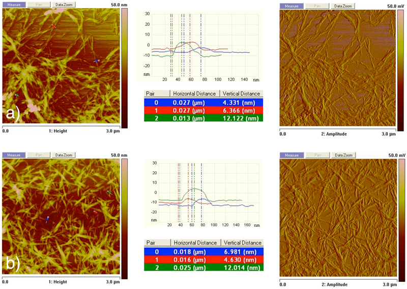
Image (AFM) of cellulose nanocrystals a isolated from MCC and b isolated from sludge
Processing of CAB–TEC fibres and their nanocomposites
The preparation of melt spun nanocomposite fibres renders many challenges, having well dispersed nanoparticles in the matrix polymers is very important for fibre spinning. Due to the similar size of the aggregated particles and fibres diameters, the aggregation can affect on the processability of the fibres and cause spin line failure. In this study two nanocomposite fibres were prepared using two different dispersion methods. Because of hydrophilicity of the CNC, they have strong tendency for aggregation when drying in non-polar solvents, thus to avoid aggregation, it is necessary to remove the water content in the mixture and exchange it to a non-polar solvent like ethanol which is soluble with the polymer. To redisperse the crystals in the solvent and in the dissolved polymer, two solvent exchange techniques were used.
In the first technique, the initial step was to exchange as much as possible water to ethanol by several centrifugation steps. The second step was to premix the CNC with dissolved CAB–TEC followed by compounding with bulk CAB using the twin screw extruder to achieve desired concentration (2 wt-%CNC).
In the second technique, the water content exchanged to ethanol almost completely by using sol–gel process and then the prepared organogel was mixed with dissolved CAB–TEC in ethanol.
The melt spinning of prepared CAB–TEC and their nanocomposites was successful for both dispersion techniques. The produced as spun fibres were uniform and had diameters in range of 550 to 650 μm.
Fibre characteristics
The results obtained from tensile tests are summarised in Table 2. It can be seen that the tensile strength and Young's modulus for nanocomposite fibres prepared by centrifuge and extrusion technique was reduced by 25 and 13% respectively, and the reduction was statistically significant. The reduction of fibres mechanical properties when different nanoreinforcements were used has been reported earlier, for instance PLA–clay bionanocomposite fibres28, 29 and for PLA–CNC bionanocomposite fibres. 23 The lower tensile properties of the nanocomposite fibres compared to the reference CAB–TEC fibres can be due to defects introduced in the fibres and because of the aggregations of the CNC in the matrix.
Mechanical properties of produced nanocomposite fibres
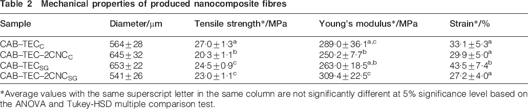
*Average values with the same superscript letter in the same column are not significantly different at 5% significance level based on the ANOVA and Tukey-HSD multiple comparison test.
The nanocomposites fibres prepared using sol–gel, showed better mechanical properties. Only a slight reduction effect on the tensile strength (3%) was seen, but the Young's modulus was improved significantly, by 17%. Although 17% increase is not too much, even this minor improvement for only 2% CNC can consider the sol–gel process as a promising method to provide homogenous dispersion of CNC in the matrix and consequently obtaining higher mechanical properties. As mentioned before, no report was found in literatures regarding mechanical properties of melt spun CAB nanocomposite fibres, but Bondeson et al. 19 prepared CAB–15%TEC–5%CNC nanocomposite films by extrusion where the nanocrystals were fed in the extruder as suspension, and then the extrudate was compression moulded to a thin film. The authors reported an improvement for modulus and tensile strength by 300 and 100% respectively. In another study done by Siqueira et al., 21 CAB–CNC films were prepared using very similar methods as we report here. They used sol–gel process followed by solution casting without using plasticiser to prepare nanocomposite films and reported improvement of 34 and 15% for tensile strength and modulus respectively. 21 The lower Young's modulus for both CAB–TEC samples in this study (0·26 and 0·29 GPa) compared to the values reported by Siqueira et al. (1·2 GPa) 21 and Bondeson et al. 19 (0·8 GPa) can be explained by the high amount of plasticiser (15%) used in this study. It is possible that the different specimen shape (monofilament fibres compared to films) for tensile testing will also affect the values.
In both samples prepared in this study, a reduction in elongation can be seen in nanocomposite fibres (11 and 38% for fibres prepared by centrifugation and sol–gel respectively). The reduction for fibres produced by centrifugation was not significant, while fibres produced by sol–gel process were significantly different. The reduction of the elongation could be probably due to improved interaction between the CAB matrix and the cellulose crystals because of the more efficient removal of water from the crystal surfaces, which might limit the polymer chains mobility.
Microscopy
Figure 6 shows the surface of CAB–TEC fibres and its nanocomposites observed in SEM. The micrographs indicate uniform diameters for fibres produced with both methods. SEM also reveals that by addition of CNC to the matrix, the surfaces of the fibres prepared by centrifugation are slightly rougher, and some clusters or agglomerates can be observed on the surface (Fig. 6c and d). By taking into account the mechanical properties, this roughness shows that CNC probably were aggregated in the matrix. As it mentioned earlier, due to the high polarity of the CNC, usually the use of surfactant or some surface modification is needed to provide well dispersed and distributed CNC in non-polar matrix such as CAB. However, in this experiment due to having solvent exchange step by centrifugation followed by several mixing and compounding steps (solution mixing, twin screw extruder and microcompounder) it was supposed to get well dispersed CNC and homogeneous structure. An increase in surface roughness was reported for PLA melt spun fibres reinforced with CNC as well; 23 however, in this case the surface roughness of CAB–CNC was much less than PLA–CNC nanocomposite fibres.
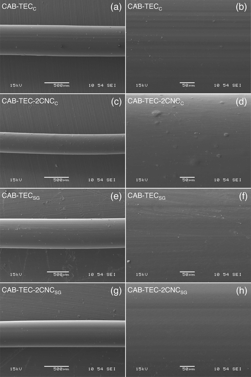
Images (SEM) of CAB–TEC fibres and their nanocomposites
In contrast to the CAB–TEC–2CNCC, the surface of the CAB–TEC–2CNCSG fibres showed no clusters and surface roughness. This can be evidence that the CNCs were uniformly dispersed and did not aggregate in the matrix.
Figure 7 shows the microstructure of the fibres obtained by optical microscopy. As it is obvious in the direct light mode images (Fig. 7a, c, e and g), nanocomposite fibre prepared by sol–gel process (Fig. 7g) has almost the same structure as pure matrix fibres (Fig. 7a and e), while nanocomposite prepared by centrifuge and extrusion has different microstructure (Fig. 7c). The transmitted light mode images (Fig. 7b, d, f and h) show some light scattering for the nanocomposite fibres (Fig. 7d and h). This light scattering is more obvious for the CAB–TEC–2CNCC fibre (Fig. 7d) compared to CAB–TEC–2CNCSG fibre (Fig. 7h), which is probably due to bigger and more clusters of CNC caused by aggregation. To confirm this idea and obtain more focused images, the films of the nanocomposite fibres were prepared and examined by the same microscopy (Fig. 8). As it can be seen in both direct and transmitted light mode, the dots are bigger and denser for the CAB–TEC–2CNCC fibre compared to CAB–TEC–2CNCSG fibre.
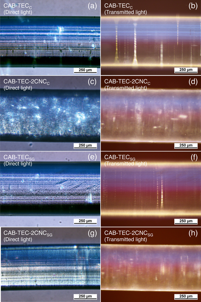
Optical microscopy images of CAB–TEC fibres and their nanocomposites
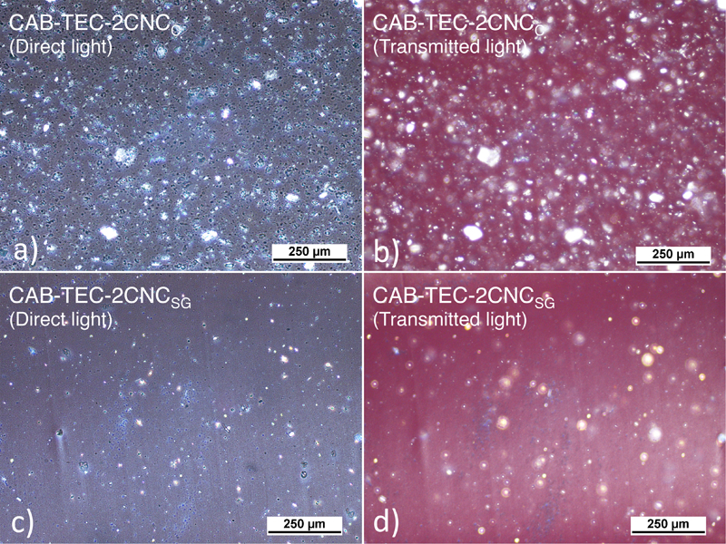
Optical microscopy images of CAB–TEC nanocomposite films
Conclusions
The objective of this study was to prepare CAB fibres with well dispersed and distributed CNC to improve the mechanical properties. To achieve this goal, two dispersion techniques were applied and the effect of the methods on the mechanical properties of the fibres was the main focus of this study.
In the first technique, CNC in water was solvent exchanged to ethanol by centrifugation and then premixed with dissolved CAB–TEC in ethanol followed by extrusion, while in the second technique, same amount of CNC in water was completely solvent exchanged to ethanol by sol–gel process and then mixed with dissolved CAB–TEC.
Nanocomposite monofilament fibres were melt spun using a twin screw microcompounder equipped with a rotating take-up roll. The spun fibres were relatively uniform and had diameters ranging between 550 and 650 μm.
The SEM study showed that addition of CNC resulted in surface roughness of the fibres prepared by the first dispersion technique (centrifugation, premixing and extrusion), while fibres prepared by sol–gel showed smoother surfaces.
Mechanical properties of the nanocomposite fibres prepared by centrifugation and extrusion were reduced compared to the reference fibres without CNC. The nanocomposite fibres prepared using the sol–gel process had positive impact on the mechanical properties; the Young's modulus was improved with 17% and the addition of the CNC did not affect the strength. The decreased mechanical properties of the fibre prepared by centrifugation together with the surface roughness and optical microscopy study, interpreted small CNC agglomerates in the CAB matrix, which affect the mechanical properties negatively. Although an increase in Young's modulus by 17% is not a dramatic improvement, it indicates that sol–gel process is a promising technique to disperse CNC in CAB without any surface modification or use of surfactant. Future work will focus on the preparation and characterisation of CAB–TEC–CNC nanocomposite fibres with an increased amount of CNC as well as solid state drawing of the fibres to align the CNC in the matrix.
Footnotes
Acknowledgements
The authors gratefully acknowledge the VINNOVA for the financial support of this work in NANOFIBRE project as well as Domsjö Fabriker AB for supplied materials.