
Abstract
In the present study, friction stir processing (FSP) was successfully carried out on Ti–6Al–4V alloy and nanocalcium phosphate (CaP) particles were incorporated during process. Subsequently, nanohydroxyapatite (HAp) film was effectively synthesised on Ti–CaP nanocomposite interlayer by sol–gel method. The Ti–CaP nanocomposite interlayer and nano-HAp film were characterised by XRD, OM, SEM and EDS. The substrate topography was studied by AFM analysis. The CaP particle size in the nanocomposite interlayer was in the range of 40–100 nm and nano-HAp film obtained was 10–12 μm thickness. It was found that the Ca/P atomic ratio is 1·67 in the nano-HAp film which changes to 1·21 in the Ti–CaP nanocomposite interlayer. Finally, the potentiodynamic polarisation of as received and coated samples in simulated body fluid solution was studied.
Introduction
Among bioceramic materials, hydroxyapatite [HAp, Ca10(PO4)6(OH)2], is one of the most important calcium phosphates which has a microstructural similarity to bone tissues.1 – 6 The orthopedic and dental applications of HAp are limited by its poor mechanical properties.7 – 9 Therefore, the combination of metallic implant and HAp coatings can be used in order to take advantage of the mechanical properties of substrate and the biocompatibility of HAp.10 – 12 Among metallic implants, Ti–6Al–4V alloy has a good biocompatibility and high specific strength which has been utilised in orthopedic applications.8,10,11 As compared with other methods that have been utilised to synthesise HAp coatings on titanium substrate, sol–gel has several advantages of changing the chemistry or processing conditions in order to modify the microstructure of coatings.13 – 15 Furthermore, surface modification has an important role in HAp coating process on Ti–6Al–4V substrate.16 There are many surface modifications for enhancing mechanical, chemical and physical properties of metallic implants, such as machining,16,17 polishing,16,18 sand blasting,16 shot peening,19,20 laser peening21 and wire brushing.22
Friction stir processing (FSP) has been demonstrated as a solid state technique to obtain a fine grained microstructure and is a novel method to produce metal matrix composites with ceramic particulates.23 – 26 The process is carried out by plunging and traversing a non-consumable rotating tool along the workpiece. The friction between the tool and the work piece raises the temperature and consequently the thermomechanical treatment is done by severe plastic deformation.24 – 26
In the current study, titanium–calcium phosphate (Ti–CaP) nanocomposite interlayer was successfully fabricated on Ti–6Al–4V substrate by inserting nano-HAp powders under the FSP tool and subsequently the nano-HAp film was synthesised on the Ti–CaP interlayer by sol–gel method in the water based suspension. The fabrication of Ti–CaP nanocomposite interlayer is considered as an efficient technique for surface modification from the biomedical viewpoint. As a result, the amount of calcium and phosphorus on Ti–6Al–4V substrate is increased by nano-CaP products that were formed by decomposition of nano-HAp powders under the FSP tool during the process. Consequently, the calcium to phosphorus atomic ratio (Ca/P) would be improved at the interface between nano-HAp film and Ti–6Al–4V substrate with regard to unmodified substrate. Furthermore, the corrosion behavior in simulated body fluid (SBF) solution of nano-HAp coated on the nanocomposite interlayer sample was discussed.
Experimental procedure
Materials
Mill annealed Ti–6Al–4V plates were used as the as received material (AR) with 3 mm thickness and the chemical composition of 6·28Al, 4·90V, 0·29Fe, 0·05Nb, 0·03Mn, 0·02Cr, 0·05Si, <0·05Sn, <0·03Mo, <0·02Cu, 0·01Zr and Ti balance (all in wt-%). The AR plates were additionally heat treated at 850°C for 1·5 h to have a fully equiaxed microstructure. In order to fabricate Ti–CaP nanocomposite interlayer, nano-HAp powders with average size of 65 nm (synthesised by precipitation method22) were used. For synthesising the nano-HAp film on the Ti–CaP interlayer, Ca(NO3)2.4H2O (Merck no. 141231) and (NH4)2HPO4 (Merck no. 21,599-6) as starting precursors and ammonia solution for pH adjustment were used. Furthermore, a natural gelatin (agar–agar) with the structure of polysaccharide was used in the resulting colloidal sol to improve sol stability.27
Friction stir processing of Ti–6Al–4V substrate
Ti–6Al–4V plates with 200 mm length, 20 mm width and 3 mm thickness were fixed on FSP machine. The tungsten carbide cylindrical tool consists of a shoulder with no pin was applied. The 3° tilt angle of fixed tool, tool shoulder diameter of 16 mm and length of 200 mm were employed. The rotation speed, advancing speed and plunge depth were set to be 250 rev min−1, 20 mm min−1 and 1·5 mm respectively. Three passes FSP was used to incorporate homogenously nano-HAp powders into Ti–6Al–4V substrate. In this regard, three parallel grooves with 1 mm depth and 2 mm width were machined out of the workpiece and separated from each other by a 2 mm distance. Subsequently, nanosized HAp powders were compacted into the grooves and FSP was carried out on the prepared sheets under an argon gas shrouding system to prevent oxidation of the Ti–6Al–4V workpiece (Fig. 1). Cross and lateral sections of the nanocomposite samples were mounted, and then mechanically polished, followed by etching in an etchant composed of 10%HNO3, 5%HF, and 85% distilled water. For the characterisation of Ti–CaP interlayer optical microscope (OM Olumpus BH-2) and scaning electron microscope (SEM Philips XL 30) were used. The surface topography of the nanocomposite sample was analysed by scanning probe microscope (SPM, DME DS-95-50E). Elemental composition of Ti–CaP nanocomposite interlayer was studied by energy dispersive spectroscopy. Finally, samples with surface area of 1×1 mm2 were cut from friction stir processed samples and prepared as substrates for synthesising nano-HAp film by sol–gel method.
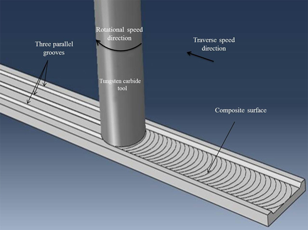
Schematic image of workpiece and tungsten carbide tool
Synthesising of nano-HAp film on modified substrate
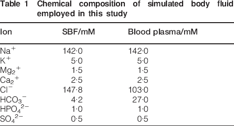
The friction stir processed samples were ground using SiC papers from 800 to 1200 grit and cleaned with deionised water. The Ca(NO3)2.4H2O particles were dissolved in 50 mL of deionised water (0·164M) at 37°C. Then, it was added to a 50 mL solution containing (NH4)2HPO4 (0·098 M) at 37°C under stirring condition. The pH value for each of above mentioned solution was adjusted above 9 by addition of strong ammonia. Subsequently, the natural gelatine (agar–agar) was added to resulting colloidal sol and then was vigorously mixed by magnetic stirrer for 2 h at 37°C. The friction stir processed samples were dipped in the HAp sol and withdrawn with the speed of 5 cm min−1. Thickness of the nano-HAp film was gradually increased by multiple dipping. After the process was completed, the coats were carefully dried in oven for 20 min. This process was repeated 6 times to increase the film thickness. Dried samples were annealed under argon atmosphere with heating rate of 500°C h−1 at 750°C for 1 h and were cooled down at the furnace. The phase composition of coated surface was analysed by XRD (Philips PW 1480), by scanning in 2θ = 20–100° range at a step size of 0·02° and a count time of 0·6 s. The microstructural characterisation of the coated sample was carried out by using SEM (Philips XL 30). Moreover, the line scanning analysis of nano-HAp film toward the Ti–CaP interlayer was studied by EDS. In order to study corrosion behaviour of nano-HAp coated on the modified Ti–6Al–4V substrate, samples with a surface area of 1 cm2 were set in cold-curing epoxy resin. Potentiodynamic polarisation tests in a corrected SBF solution at temperature of 37°C and pH of 7·40 were carried out by means of Autolab Pgstat 30. The chemical composition of the working SBF is presented in Table 1. Two parallel graphite rods served as the counter electrode for current measurement and the potentials were measured with regard to a saturated calomel electrode. Samples were immersed into the SBF solution and allowed to be stabilized for 5 min in order to ensure a steady open circuit potential (OCP). Then, the potential was increased at a rate of 1 mV s−1 from 200 mV below the OCP, and the scan was stopped when it reached 400 mV. The corrosion parameters were estimated from the polarisation curve by using Tafel extrapolation method via Nova v1·6 software.
Chemical composition of simulated body fluid employed in this study
Results and discussion
Characterisation of Ti–CaP nanocomposite interlayer
Figure 2 shows optical micrographs of stir zone after three passes FSP. The thickness of the friction stir processed zone is ∼200 μm wherein nanosized CaP particles were found to be incorporated due to the occurrence of vigorous stirring during the process. Figure 2a demonstrates an appropriate continuity between the nanocomposite layer and Ti–6Al–4V substrate and no defects are visible at the interface. Figure 2b confirms that the grain size decreases in the stir zone during FSP. Dynamic recrystallisation (DRX) is regarded as dominant mechanism that decreases the grain size in the stir zone during FSP on the Ti–6Al–4V substrate.24 – 26,28 During the process, high temperature and severe plastic deformation cause softening and work hardening, respectively. The severe plastic deformation increases the dislocation density nearby the grain boundaries and high temprature leads to subgrain formation by annihilation of dislocations and as a result, new dislocation free grains are nucleated.28
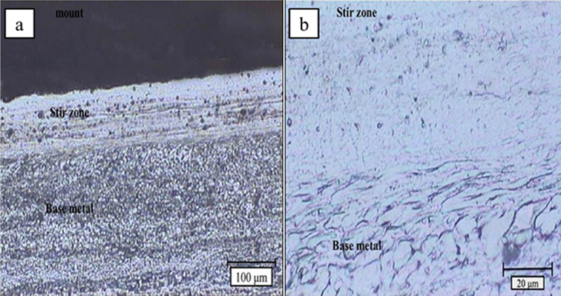
Optical micrographs of fabricated Ti–CaP nanocomposite interlayer
Figure 3a shows SEM image obtained from the surface of nanocomposite fabricated by three passes FSP. It is clear that, CaP particles (the white regions) are distributed homogeneously by three passes FSP. In addition, the average CaP particle size was estimated to be lower than 100 nm. The EDS analysis on the CaP particles within the Ti–6Al–4V matrix including the atomic percentage of O, P, Ca and Ti elements are illustrated in Fig. 3b. The resulting Ca/P atomic ratio was obtained about 1·21 which proves that HAp particles were decomposed into other calcium phosphates phases. This value is between 1 and 1·33 which are known for dicalcium phosphate anhydrous (DCPA) and octacalcium phosphate (OCP) respectively.4 In consequence, the high temperature of process and vigorous stirring during the process promote decomposing of HAp particles into other CaP phases such as DCPA and OCP. The EDS mapping image of Ca, P, O and Ti elements on the nanocomposite surface are illustrated in Fig. 3c showing that CaP particles were homogenously mixed on the surface.
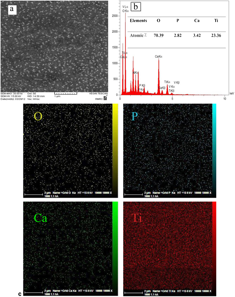
a Image (SEM), b EDS spectrum and c EDS mapping image of Ti–CaP nanocomposite interlayer fabricated by three passes FSP
The AFM image presented in Fig. 4 depicts the surface topography and nano-CaP particles distribution on the nanocomposite surface. Figure 4a shows three-dimensional topography of the nanocomposite surface. It was observed that the maximum and average heights from the surface are 107 and 98·6 nm respectively. Surface topography profile along z axis for an arbitrary direction is illustrated in Fig. 4b. The peak width depicts the average size of CaP particles which was obtained 46·4 nm and it confirms the results shown in Fig. 3a.
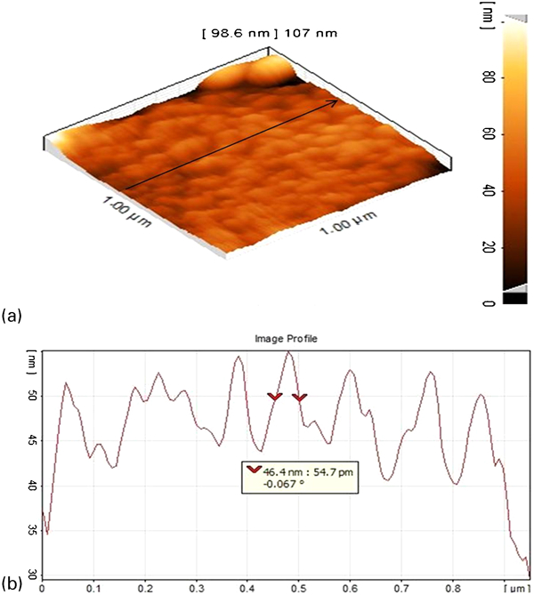
a three-dimensional AFM topography image and b surface topography profile along z axis for arbitrary direction on Ti–CaP nanocomposite interlayer
Characterisation of synthesised nano-HAp film on modified substrate
Figure 5 shows the XRD pattern of HAp film on the modified Ti–6Al–4V substrate after heat treatment for 2 h at 750°C. The XRD analysis of samples proved the high crystallinity of nano-HAp film and also indicated the presence of TiO2 (rutile) in the synthesised layer. The film was mainly composed of Ti, rutile and HAp. The rutile phase was formed in the film by reaction between Ti and O during sintering. In the XRD pattern, the peaks at 22·8, 26·1, 32·3, 32·7, 34·2, 44·2 and 48·2° are consistent with the (200), (201), (121), (112), (202), (113) and (320) Bragg reflections of HAp respectively. Meanwhile, XRD peaks at 2θ = 27·3, 36, 41·1, 54·6, 56·4, 64·3 and 68·8° can be assigned to the diffraction of (110), (101), (111), (211), (220), (310) and (301) planes of TiO2.
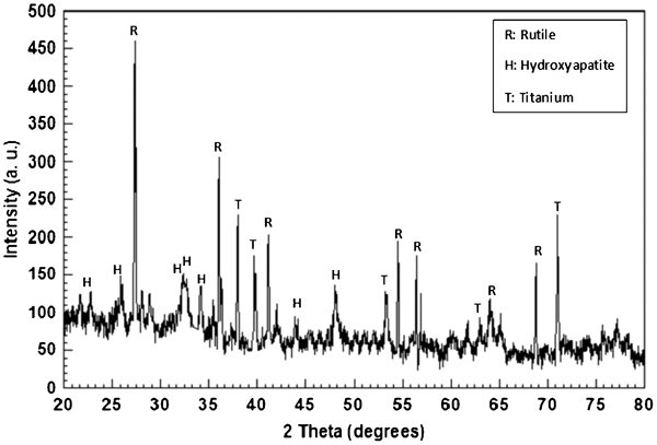
X-ray diffraction pattern of nano-HAp film coated on modified Ti–6Al–4V substrate after heat treatment for 2 h at 750°C
Figure 6a shows the cross-sectional view of the nano-HAp film on the modified substrate. The uniform HAp film with 9–12 μm thickness is obtained. The SEM image shown in Fig. 6b depicts that a relatively rough and nanoporous structure of nano-HAp film was achieved on the modified Ti–6Al–4V substrate after heat treating the sample at 750°C.
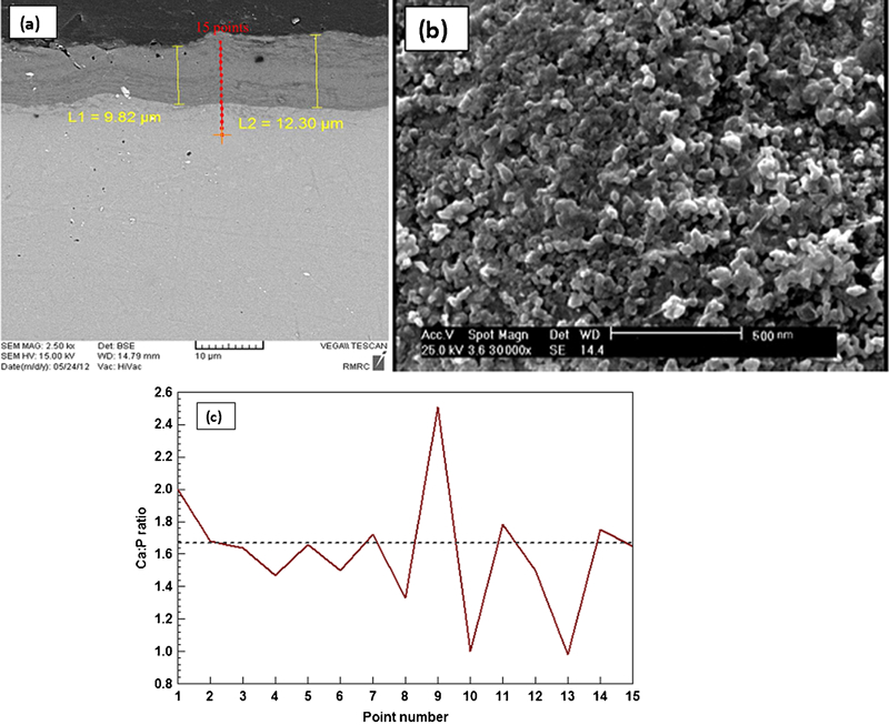
Images (SEM) of a cross-sectional view, b surface of nano-HAp film onto modified Ti–6Al–4V substrate and c EDS line scanning profile indicating variation of Ca/P atomic ratio through nano-HAp film toward modified substrate
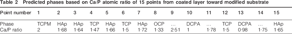
The Ca/P atomic ratio variation was studied from the nano-HAp film toward the modified substrate by EDS (Fig. 6c). The line scanning analysis was carried out through 15 points (8 points in nano-HAp film, 3 points near the interface and 4 points in nanocomposite interlayer). The phases predicted to be stable for each point are presented in Table 2. The Ca/P atomic ratio is approximately 1·67 for the points which are in the vicinity of the nano-HAp film. This shows that HAp is the most stable CaP phase in the nano-HAp film.4 However, for the points at interface or nanocomposite interlayer, other CaP phases such as tricalcium phosphate (TCP) and DCPA are specifically stable due to its Ca/P atomic ratio.4
Predicted phases based on Ca/P atomic ratio of 15 points from coated layer toward modified substrate
Potentiodynamic polarisation study in SBF solution
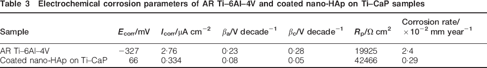
The potentiodynamic polarisation curves of AR Ti–6Al–4V and coated nano-HAp film on Ti–CaP layer in the corrected SBF solution are depicted in Fig. 7. The corrosion parameters (βa, βc, Icorr and Ecorr) are extrapolated from polarisation curves by using Tafel least square fitting method and presented in Table 3. The polarisation resistance Rp was calculated by using Stern–Geary equation29
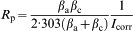
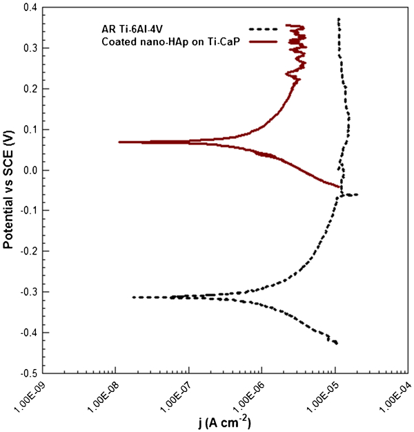
Potentiodynamic polarisation curves of AR Ti–6Al–4V and coated nano-HAp on Ti–CaP nanocomposite interlayer in corrected SBF solution
Electrochemical corrosion parameters of AR Ti–6Al–4V and coated nano-HAp on Ti–CaP samples
Conclusion
Friction stir processing as a surface modification method was carried out on Ti–6Al–4V substrate to incorporate the CaP particles and fabricate Ti–CaP nanocomposite interlayer. Then, sol–gel method was utilised to form the nano-HAp film on the modified surface and the results indicated as follows.
The CaP particle size in the composite layer was acquired in the range of 40–100 nm.
The sol–gel derived nano-HAp film was obtained 10–12 μm thickness on the nanocomposite interlayer.
According to EDS analysis from nano-HAp film toward the modified substrate, the Ca/P atomic ratio is about 1·67 in the coated film. However, it is less than 1·67 in the friction stir processed substrate. The high temperature and severe plastic deformation during FSP promote decomposing of HAp particles into other CaP phases such as DCPA, TCP and OCP.
Based on the electrochemical corrosion behaviour of nano-HAp film on Ti–CaP sample in SBF solution at 37°C, the corrosion current density and corrosion rate significantly decreased after nano-HAp coating on Ti–CaP sample while corrosion potential and linear polarisation resistance were increased.