
Abstract
Ongoing research in the area of adhesive bonding is focused on the optimization of the bonding method used as well as on the use of newly developed high quality adhesives. In this work, the bonding quality of adhesively bonded composite U-joints was experimentally investigated using C-Scan ultrasonic inspection. The reference adhesive used was Epibond, while the newly developed adhesive was the one developed within the ABITAS project. Based on the geometry of the U-joint, different scan areas of the two existing bondlines were defined in order to effectively capture the quality of the entire bonded area. Furthermore, two different bonding methods were evaluated in terms of bonding quality assessed through the ultrasonic inspection tests. In this frame, U-joints including normal cured and spot cured bonded areas have been investigated. The evaluation was carried out on the basis of the total defected area by using the clustering mode of ULTRAWIN image analysis software. This mode enables the quantitative assessment of the defective percentage (%) out of the total scanned area. The results reveal a significant amount of voids in the components investigated. In most cases, spot curing areas are clearly distinguishable. The spot curing process causes a variation of the adhesive layer thickness and the creation of bubbles. Comparison between the conventional and the newly developed adhesive was made; for components using the conventional adhesive, damage is located mostly around the rivets, probably due to the increased local pressure.
Introduction
The progress accumulated over several decades on the technologies of fibre reinforced polymers led to a dramatic increase in the use of composites in modern civil aircraft primary structures. Apart from the established manufacturing methods (e.g. autoclave curing) as well as the promising alternative routes (e.g. infusion of integrated dry preforms), the composites assembly is a typical solution for making integral parts. Currently, in aerostructures, carbon fibre reinforced plastics are being mainly assembled by mechanical fasteners. This type of design implies weight penalties emanating from the need to deal with the stress concentrations developed around the bolts. Moreover, bolts and rivets damage the continuous reinforcing fibres and consequently, can greatly affect the overall load carrying capacity of the structure. 1 Owing to the possibility of cocuring, adhesive bonding is the most desired alternative joining method for composite structural parts as it provides significant cost and weight savings. Adhesive bonding of aerospace components is a fabrication technique which has increased markedly in popularity during the last two decades and currently is a focal point in many studies regarding aging aircraft.
Military applications initiated the use of adhesively bonded advanced composites, and aircrafts such as the F-18 and the F-22 employ significant amounts of bonded polymer matrix composite laminates at wing skins and control surfaces. 1 Similar applications may be found on many types of commercial aircrafts whose economical operations benefit considerably from the reduced weight offered by the bonded composite assemblies (e.g. AIRBUS A380, Fig. 1). 2
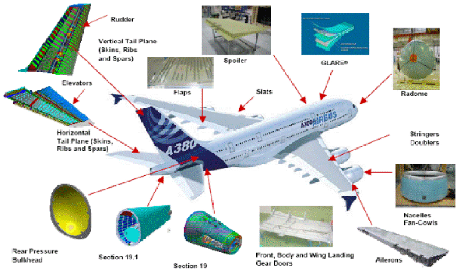
Adhesive bonding applications at new AIRBUS A380 2
Moreover, the component under investigation as well as L, H and T shaped profiles comprise a family of modular profiles which are destined to replace mechanical fasteners in the assembly of aircraft structural parts. However, in order to benefit from this enhancement in strength of the joint, effective bonding must be also ensured. On the other hand, the limited mechanical properties of the adhesive represent a drawback for the widespread use of adhesive bonding.2, 3 Furthermore, past difficulties with surface preparation and troubles with associated environmental durability obstruct the establishment of adhesively bonded joints as a reliable joining method for composite parts. At present time, despite prior success in metal and composite bonded joints and repairs, a number of questions still remain regarding durability and damage tolerance of adhesive bondline. Despite dimensionally small compared with the adherents, the bondline contains not only the adhesive but also interphase regions and is the crucial part of any bonded structure, regardless of the adherent materials. Thus, understanding the effect of defects on the adhesive is necessary for assessing the performance of bonded structures. This issue is of critical importance in the current climate of extending the lives of existing aircraft and of creating new designs intended for operational periods measured in decades rather than years. 3
Ongoing investigation towards the establishment of adhesive bonding is focused on the development of new bonding processes, which could minimise the presence of defects in the bondline, new adhesives of increased mechanical performance and improved surface treatments prior the bonding. Ultrasonic inspection of adhesively bonded composite joints which are capable of being used in structural aeronautic applications is a subject of nowadays edge research. A representative one is an investigation conducted on Pi joints. 4 In Ref. 4, beside the joining advantages mentioned previously, the Pi shaped profiles were found also capable of joining panels in a vertical T shaped configuration something impossible by mechanical fastening.
Within the frame of the intense investigation currently being conducted on the quality of adhesively bonded joints, in this work, the bonding quality of adhesively bonded composite U-joints was experimentally investigated using C-Scan ultrasonic inspection. The reference adhesive used was Epibond, while the newly developed adhesive was the one developed within ABITAS project. 5 Based on the geometry of the U-joint, different scan areas of the two existing bondlines were defined in order to effectively capture the quality of the entire bonded area. Furthermore, two different bonding methods were evaluated in terms of bonding quality assessed through the ultrasonic inspection tests. In this frame, U-joints including normal cured and spot cured bonded areas have been investigated. The evaluation was carried out on the basis of the total defected area.
Geometry and materials
Adhesively bonded U shaped joints between carbon fibre reinforced plastic laminates have been considered (Fig. 2a).
5
The U shaped profile is used as a stiffener in one of EUROCOPTER's helicopter skin panels (Fig. 2b).
5
The laminates are made from eight layers of the prepreg AS4/8552 composite material stacked in the
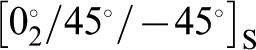 sequence. Bonding was achieved by using two different epoxy adhesives, namely, the Epibond 1590 A/B,
6
which has been considered as a reference in this study, and the newly developed epoxy LMB adhesive.
5
The Epibond 1590 A/B adhesive is an aerospace qualified adhesive for structural bonding, while the LMB adhesive is an advanced prototype two-component paste adhesive, which is processed by mix dosing and exhibits long assembly time with medium temperature cure profile. The new adhesive shows improvements over Epibond 1590 A/B on peel performance, open time, hot/wet Tg and processing (slump).
6
Moreover, the LMB adhesive showed a better fracture resistance and shear behaviour compared to the Epibond 1590 A/B adhesive in experimental investigation conducted in Ref. 7. The experimental configuration used for the adhesion process is schematically described in Fig. 2c. The mean thickness of the bondline is 0·55 mm and the mean bondline width was 25 mm. Moreover, in all components investigated, two different curing methods were used in combination, namely, the typical one by means of oven as well as local spot curing using resistant heaters. The total number of beams was 4 (Fig. 3).
sequence. Bonding was achieved by using two different epoxy adhesives, namely, the Epibond 1590 A/B,
6
which has been considered as a reference in this study, and the newly developed epoxy LMB adhesive.
5
The Epibond 1590 A/B adhesive is an aerospace qualified adhesive for structural bonding, while the LMB adhesive is an advanced prototype two-component paste adhesive, which is processed by mix dosing and exhibits long assembly time with medium temperature cure profile. The new adhesive shows improvements over Epibond 1590 A/B on peel performance, open time, hot/wet Tg and processing (slump).
6
Moreover, the LMB adhesive showed a better fracture resistance and shear behaviour compared to the Epibond 1590 A/B adhesive in experimental investigation conducted in Ref. 7. The experimental configuration used for the adhesion process is schematically described in Fig. 2c. The mean thickness of the bondline is 0·55 mm and the mean bondline width was 25 mm. Moreover, in all components investigated, two different curing methods were used in combination, namely, the typical one by means of oven as well as local spot curing using resistant heaters. The total number of beams was 4 (Fig. 3).
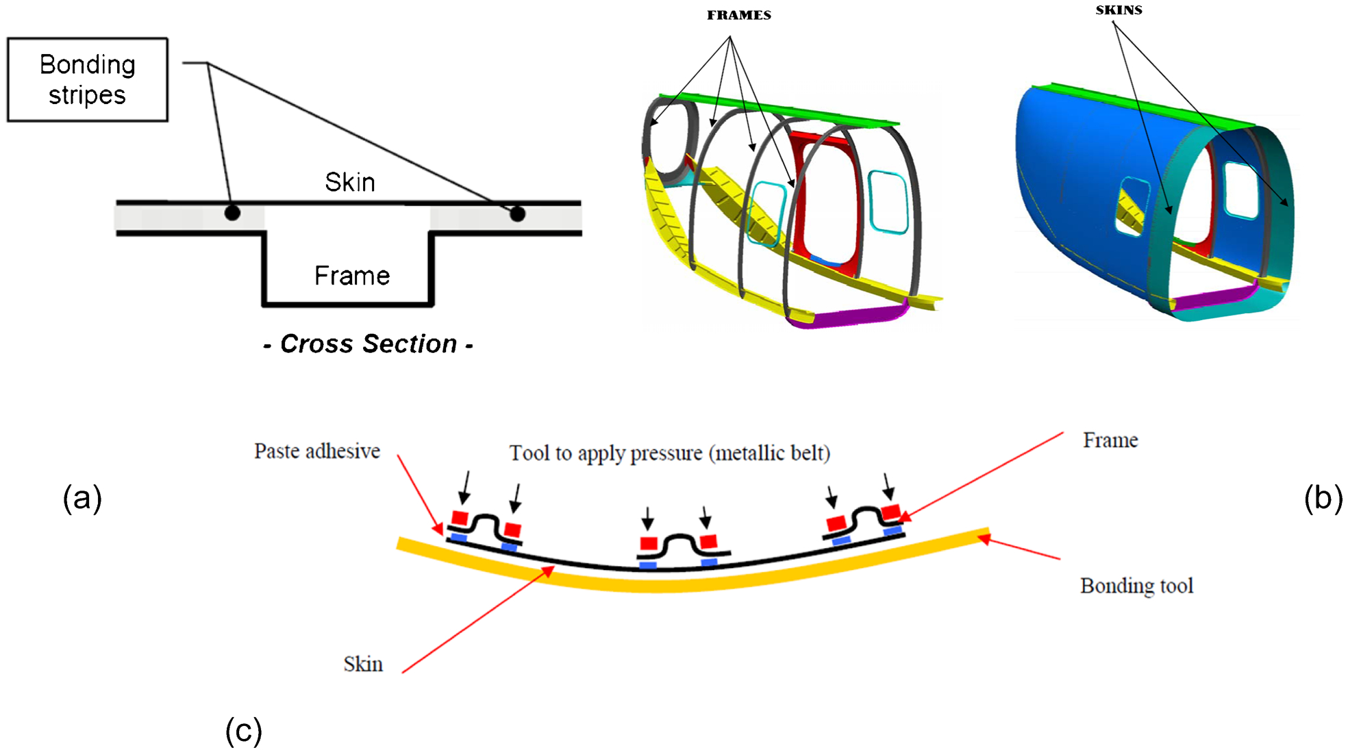
a U profile considered, b stiffened helicopter panel and c experimental configuration of adhesive bonding process 5
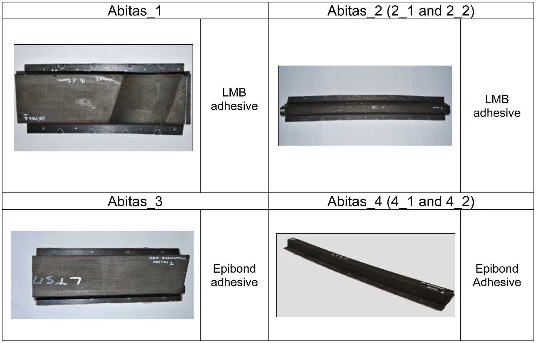
Components investigated where both LMB and Epibond adhesive were used, as well as typical curing and spot curing was applied
Ultrasonic inspection of bonding quality
Experimental investigation
The quality of the bondline was checked using ultrasonic C-Scan inspection. To this end, the ULTRAPAC II system (automated immersion system) of the Physical Acoustics Corporation was used in association with the ULTRAWIN software 8 for data acquisition, control and imaging. Tests have been carried out using the pulse echo method with the gates being synchronised with the max echo. Different scan areas from the bottom of the bondlines were accordingly defined in order to effectively capture the quality of the entire bonded area of each investigated component. The scan areas of the investigated parts are shown in Figs. 4–7. The remained holes from the supplementary bolted joints are also shown. Each scan area has different slope and the UT sensor was placed perpendicularly in order to achieve maximum scanning resolution.
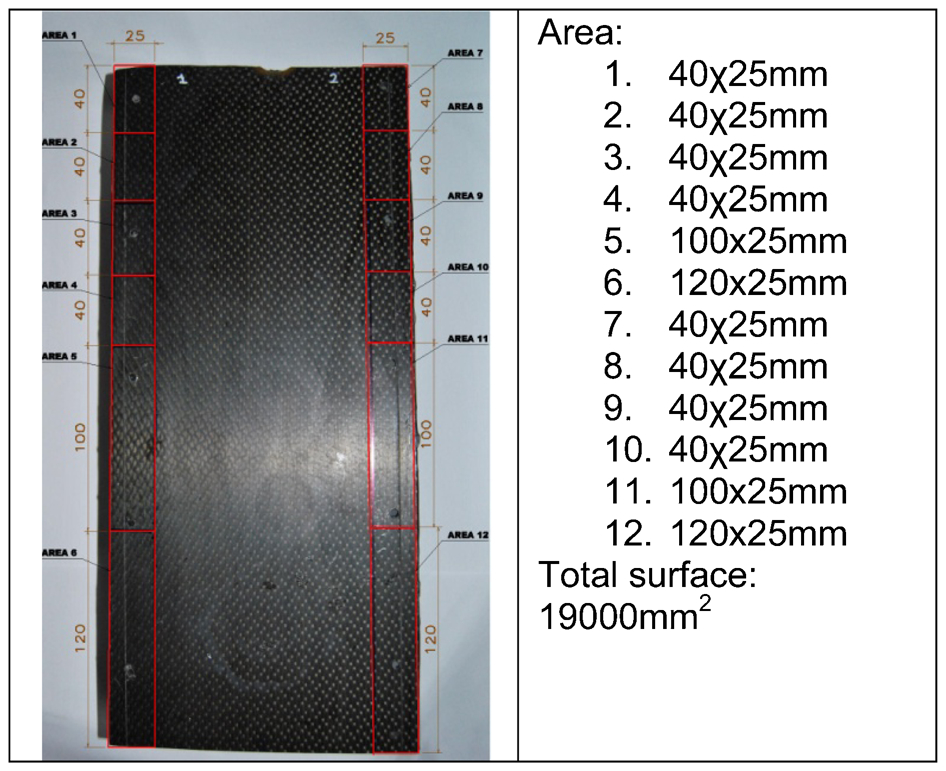
Scan areas defined for component Abitas_1
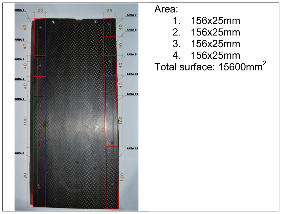
Scan areas defined for component Abitas_3
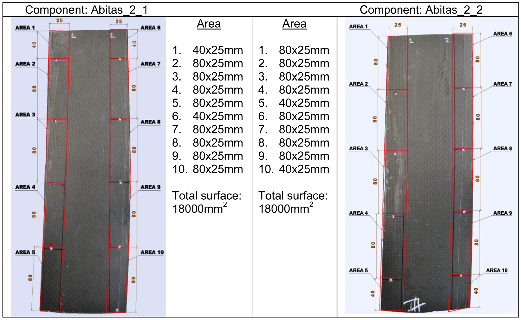
Scan areas defined for component Abitas_2 (cut in two parts Abitas_2_1 and Abitas_2_2 to enable correct placement inside C-Scan bath)
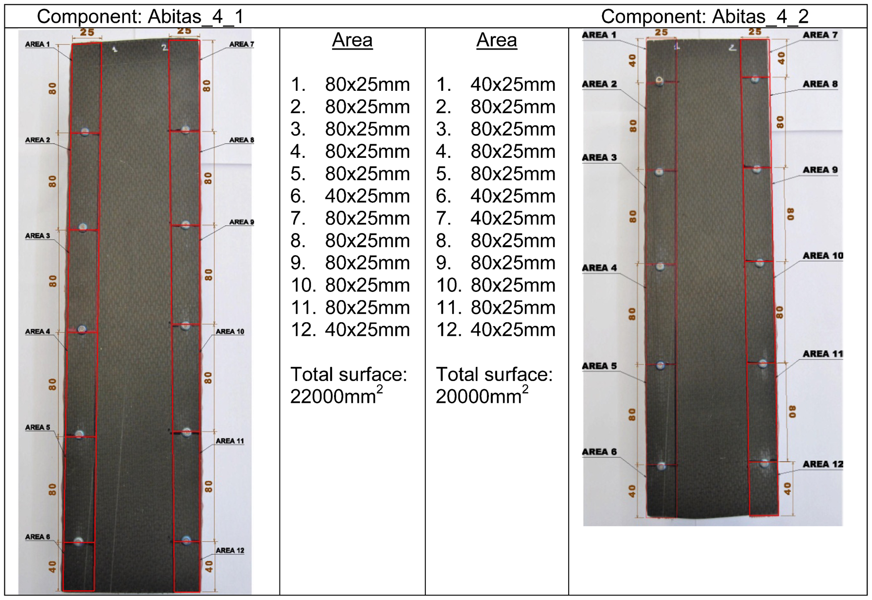
Scan areas defined for component Abitas_4 (cut in two parts Abitas_4_1 and Abitas_4_2 to enable correct placement inside C-Scan bath)
The C-Scan experiments were focalised to the bonded areas. Concerning the position of the scanning gates, for the case of LMB newly developed adhesive two gates were used, while for the case of EPINOBD reference adhesive, only one gate was used. The first gate was focused between the two laminates,covering the adhesive volume. Defective areas are represented with red colour. Defects are caused mainly by bubbles. Amplitude exceeding 70% of full screen height (FSH) is considered as defect. The second gate was focused at the backwall eco for confirming the results of the fisrt gate. Defective areas are represented in blue colour. High attenuating signal implies porous bonding or defects which are cleearly visible at the first gate. For the numerical evaluation, data from the first gate are used only. The C-Scan settings and gates used are summarised in Tables 1 and 2 respectively.
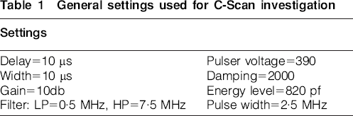
General settings used for C-Scan investigation
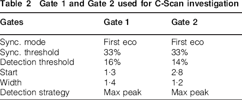
Gate 1 and Gate 2 used for C-Scan investigation
C-Scan images
The C-Scan images for the above cases along with the scale of the acoustic energy reflection are depicted in Figs. 8 and 9. Defective areas are represented in red colour (very dark grey) and in blue colour (very dark grey) for the Gate 1 and Gate 2 respectively. Amplitude exceeding 70% of FSH is considered as defect. High attenuating signal implies porous bonding or defects which are cleearly visible at the first gate.
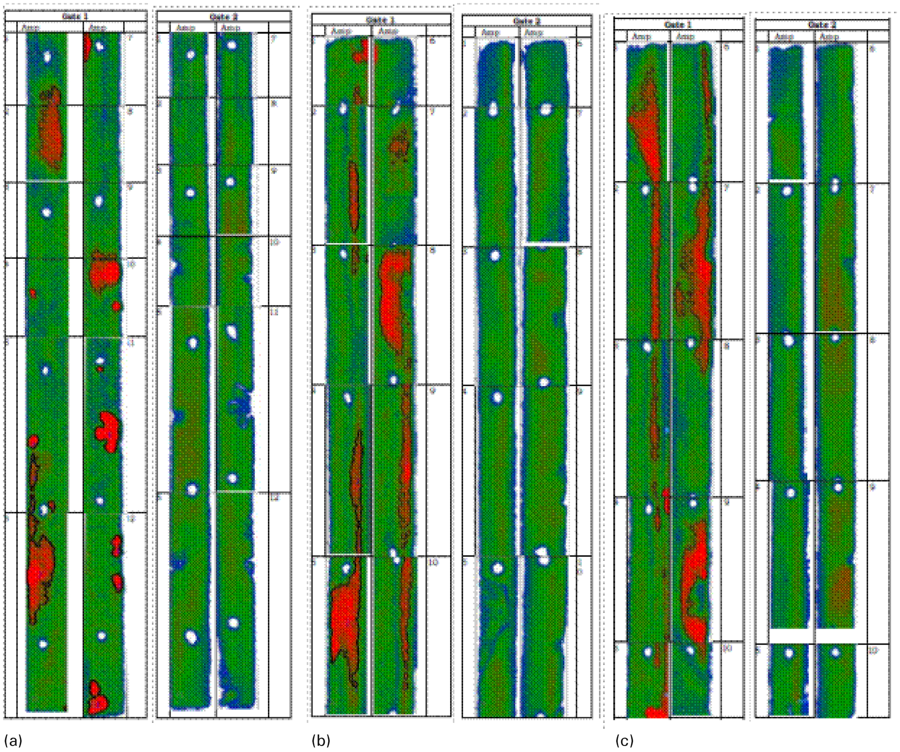
C-Scan images obtained for both gates of a Abitas_1, b Abitas_2_1 and c Abitas_2_2
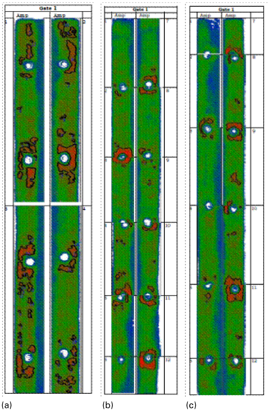
C-Scan images obtained for a Abitas_3, b Abitas_4_1 and c Abitas_4_2
The C-Scan scale is:
Red colour corresponds to 100% FSH (very dark grey)
Green colour corresponds to 50% FSH (dark grey)
Blue colour corresponds to 0% FSH (grey)
Refering to the first component under investigation, the total lack of bond area is 2022·981 mm2 (10·64% of the total bondline) and the spot cured areas, which were located between the holes are clearly visible in most area cases. Most damage is found in sc. area 6 evaluated at 640 mm2. Only in sc. areas 4 and 12, damage is limited to one or two bubbles which are located at the outer limit of the bondline. In sc. areas 5 and 6. a ‘line’ connecting the spot cured areas is found. Red (very dark grey) spots in sc. area 7 and lower in sc. area 12 are caused by lack of adhesive at the inner side of the bondline. The C-Scan resulting from the second gate provides better resolution of the boundaries of the defects. Each area coloured in blue (very dark grey) corresponds to a defect found in first C-Scan.
Concerning Abitas_2_1 and 2_2 parts, the total lack of bond area is 5860·85 mm2 (16·27% of the total bondline). In many sc. areas (e.g. 2, 4, 9 and 10 of 2_1, 2, 3 and 4 of 2_2) highlighed areas represent a reduction of the adhesive layer thicknes allong with voids probably coused by the spot curing processs. In sc. areas 1 and 6 of Abitas_2_1, red (very dark grey) spots at the top are coused by lack of adhesive at the inner side of the bondline.
Concerning the Abitas_3 as well as Abitas_4_1 and 4_2 parts, the total lack of bond area is 1630 mm2 (10·45% of the total bondline), 1152 mm2 (5·23% of the total bondline) and 920 mm2 (4·6% of the total bondline) respectively. For both cases, a difference in eco amplitude around the rivets is observed, which is considered as damage probably caused by the increased local pressure. However, the quality obtained is by far higher as compared to the components where the new LMB adhesive was used.
Conclusions
An extensive non-destructive testing study on the imperfect bonding of U shaped composite bonded joints was conducted. Ultrasonic inspection was employed to detect imperfect bonding. The study is summarised as follows.
A significant amount of voids was detected in all parts tested, in which the LMB adhesive had been used. To this end, the components contained the LMB adhesive, revealed through the ultrasonic inspection process, significant amounts of defects (bubbles, lack of adhesive).
At the specimens involving the well established EPIBOND, adhesive damage is located mostly around the rivet holes, probably due to the increased local pressure.
All scanned areas included spot and typical cured adhesions. In most cases, spot curing areas are clearly distinguishable. In this frame, the spot cured areas exhibited much higher density in terms of defects as compared to the normal cured areas. The spot curing process causes a variation of the adhesive layer thickness and the creation of bubbles.
However, a comprehensive study on the decipherment of the C-Scan images regarding the type and extent of the defects they indicate as well as their correlation with continuum mechanics methods is necessary to provide more stable conclusions for future use.
The final evaluation of the bonding quality between spot cured and normal cured areas will take place after the conduction of the mechanical tests.
Footnotes
Acknowledgements
The current research was conducted within the frame of the EU Project ‘ABITAS’ (Advanced Bonding Technologies for Aircraft Structure). Financial support provided by the European Commission under contract no. 030996 (FP6) is gratefully acknowledged.