
Abstract
The aim of this work was to study preparation and characterisation of layered double hydroxides (LDHs) and their effects on the mechanical and flame-retardant properties of ethylene propylene diene (EPDM) polymer. A series of Mg–Al, Ni–Al, and Cu–Al hydrotalcite-like compounds were prepared. The surface morphology, interlayer space, interlamellar structure, and thermal properties of these LDHs were investigated. Results showed that a best thermal stability could be obtained with Cu–Al–LDHs as the most effective components. EPDM/Cu–Al–LDHs composites were prepared by conventional compounding with EPDM and Cu–Al type of LDHs. The cure characteristics, tensile strength, wear resistant, and flame-retardant properties were investigated. The best properties were observed for 10 phr of Cu–Al–LDHs filled composite, which resulted in no obvious changes of tensile strength, increased thermal stability, 45% decrease in abrasion loss, and 53% increase in vertical burning time, respectively, compared to that of pure EPDM matrix.
Introduction
Ethylene propylene diene monomer, also called EPDM, is one of the most widely used and fastest growing synthetic rubbers having both specialty and general-purpose applications. EPDM rubbers are valuable for their excellent resistance to heat, oxidation, ozone, and weather aging due to their stable polymer backbone structure. As non-polar elastomers, they have good electrical resistivity, as well as resistance to polar solvents, such as water, acids, alkalis, phosphate esters, and many ketones and alcohols. However, one of the setbacks of these synthetic rubbers that limit their usages for highly demanding applications is its inherently high flammability.1, 2
The use of flame-retardant additives allows their fire properties to be optimised. 3 Potential approaches for fire retarding of these polymers were focused on two main approaches, that is, halogenated additives at low loading level or high loadings of aluminium hydroxide (ATH), neither of which were satisfactory. The traditional halogen based flame retardant additives can reach better flame-retardant effect, but it will release poisonous hydrogen halogen gas and have harm to the human body and environment. Inorganic flame-retardant fillers, ATH, need high quantity to satisfy the flame-retardant requirement and this may influence the application properties of polymeric materials. 4 The mechanical properties of rubber vulcanisate decreased when increasing the content of ATH, while the flame resistance was improved. Wu and Luo 5 obtained the results that the oxygen index of the vulcanisate was 19·3% when the content of ATH was 0 phr, and the oxygen index was 40·2% when the content of ATH was 200 phr. Also, the vertical combustion grade achieved FV-0 when the content of ATH was 140 phr. Guo and Luo 6 demonstrated that when the total amount of ATH was 80 phr, the oxygen index of EPDM was 27%, but its physical properties were on an obvious decrease.
Layered double hydroxides (LDHs), also known as hydrotalcite-like compounds, have recently attracted increasing attention because of their potential applications in many areas.7, 8 Kuila et al. 9 prepared rubber nanocomposites containing ethylene vinyl acetate (EVA) having 60 wt-% of vinyl acetate content and organo-modified layered double hydroxide (DS-LDH) as nanofiller by solution intercalation method. EVA/DS-LDH nanocomposites showed improved mechanical properties such as tensile strength and elongation at break in comparison with neat EVA. Costa et al. 10 demonstrated that the organically modified layered double hydroxide (O-LDH) and the dispersed filler particles could significantly influence the crystallisation process. The effect of size of the organic modifier was obviously visible on the interlayer distance of O-LDH and also on the morphological reorganisation of the dispersed O-LDH particles during vulcanisation process. Pradhan et al. 11 prepared silicone rubber SR/Mg–Al LDH nanocomposites by the solution intercalation of SR cross-linked by a platinum catalysed hydrosilylation reaction into the galleries of dodecyl sulphate intercalated layered double hydroxide (DS-LDH). The tensile strength and elongation at break of SR/DS-LDH (5 wt-%) were maximally improved by 53 and 38%, respectively, in comparison with those of the neat polymer. In conclusions, the industrial applications of LDHs in rubber systems focused on the improvement of tensile properties. However, decomposition of LDHs at moderate temperatures leads to mixed oxides with high thermal stability that are of interest in flame-retardance for polymeric matrix.
This work reported on the preparation and application of newly synthesised LDHs as reinforcing and flame-retardant agents for EPDM. Different types of LDHs, Mg–Al–LDHs, Ni–Al–LDHs, and Cu–Al–LDHs, were prepared by coprecipitation method using NaOH and Na2CO3 as precipitation agents. These LDHs agents were analysed by Fourier transform infrared spectroscopy (FTIR), scanning electron microscopy (SEM), X-ray diffraction (XRD), and thermogravimetric analysis (TGA). Then, one type of these agents, Cu–Al–LDHs, was selected and incorporated into EPDM. The properties of these EPDM composites, such as cure characteristics, tensile strength, elongation at break, thermal stability, and flame-retardance were researched and compared.
Experimental
Preparation of LDHs
Mg–Al, Ni–Al, and Cu/Al type of LDHs were prepared by coprecipitation at pH = 10 under vigorous stirring. A solution containing Al(NO3)3.9H2O with Mg(NO3)2.6H2O, or Ni(NO3)3.9H2O, or Cu(NO3)2.6H2O, in a certain atomic ratio (Al/Mg = 1∶3, Al/Ni = 1∶3, Al/Cu = 1∶3) and a mixed solution of NaOH and Na2CO3([OH−]/[
 ] = 2) were added dropwise simultaneously to a three-necked round-bottom flask containing 200 mL of distilled water. The slurry obtained was aged at 40°C for another 30 min under stirring. The mixture was then aging at 50°C for 12 h, and then filtered and washed with distilled water. After washing, the precipitate was collected by centrifugation and dried over-night at 100°C. Thus, the different types of LDHs, such as Mg–Al–LDHs, Ni–Al–LDHs, and Cu–Al–LDHs were obtained.
Preparation of EPDM/LDHs composites
Different rubber additives shown in Table 1 were added into the EPDM systems on a twin roll mill. After mixing for 20 min at the temperature about 40°C, different amounts of selected LDHs were added, and mixing for about 10 min and then EPDM/LDHs composites were prepared. Then, these mixtures were moulded in a dumbbell mould. Curing was conducted at 170°C for 30 min, after which elastic vulcanisates were obtained.
Formulation of EPDM vulcanisates
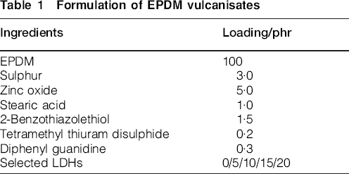
To compare the physical, mechanical, and flame-retardant properties of different EPDM composites, following formulation, which is presented in Table 1, was used. EPDM, (ethylene propylene diene monomer, 66% ethylene, 30% propylene and 4% ethylene norbornene), industrial grade, was supplied by Shanghai Hongshun Co. Ltd (Shanghai, China). Sulphur and zinc oxide, chemical grade, were supplied by Shanghai Guoyao Chemical Group (Shanghai, China). Stearic acid, analytical grade, was supplied by Shanghai Lingfeng Chemical Agent Co. Ltd (Shanghai, China). 2-Benzothiazolethiol, tetramethyl thiuram disulphide, and diphenyl guanidine, chemical grade, were supplied by Shenyang Leshan Chemcial Additive Co. Ltd (Shenyang, China).
Characterisation
Fourier transform infrared spectroscopy spectra of LDHs were obtained using a spectrometer (model Avatar 370; Nicolet Corporation). The scanning range was from 4000 to 700 cm−1 with a resolution of 2 cm−1. Samples were ground and mixed with KBr to form pellets. Sixty-four scans were necessary to obtain spectra with good signal to noise ratios.
X-ray diffraction patterns of LDHs were obtained by packing the air-dry, finely ground samples into an aluminium sample holder, and scanning from 5 to 80° of 2θ at a rate of 2° min−1. A Rigaku D-Max/400 X-ray diffractometer and goniometer (Japan) was used. The X-ray beam was nickel filtered Cu Kα (λ = 0·154 nm) radiation operated at 50 kV. The corresponding basal (d001) spacings were derived from the first order reflections by applying Bragg law.
Scanning electron microscopy of LDHs was observed using a Hitachi S-2150 scanning electron microscope. The SEM was taken using an electron beam potential of 25 kV. The specimens were previously coated with a conductive gold layer.
Thermogravimetric analysis of LDHs and EPDM/LDHs composites was carried out at 20°C min−1 under nitrogen using a Linseis PT-1000 microbalance. In each case, the mass of the sample used was fixed at 10 mg. The samples were positioned in open vitreous silica pans. They were examined at temperature ranging from room temperature to 700 or 600°C.
The curing parameters of EPDM/LDHs composites were determined on an oscillating disk rheometer (MDR-2000, Wuxi, Liyuan, China) according to ASTM D 2084-81. The compositions were then vulcanised at 170°C during the respective optimum cure time under 15 MPa pressure on an electrically heated press. In order to compare test results conveniently, all of the uncured mixes and vulcanisates in this paper were prepared using the above conditions and the formulation shown in Table 1.
The mechanical properties of the vulcanisates were measured with dumbbell specimens (6 mm wide in cross-section) according to the Chinese National Standard GB 528-82. The value for each sample was taken as the median value of five specimens. These tests were carried out at room temperature on a universal tensile testing machine (TCS-2000, Dongguan, China) with a crosshead speed of 500 mm min−1. The tensile specimens for each composition were tested, and the stress and strain at break were determined.
The wear resistant tests of the vulcanised rubber composites were conducted on a WML-76 Akron abrasion testing machine according to the Chinese National Standard GB/T1689-1998. The rotating velocities of the sample wheel and the emery wheel were 76 and 33 rev min−1, respectively. The angle between the shafts of the two related wheels was 15°. A pressure of 26·7 N was loaded on the sample during the wearing.
The vertical burning tests were carried out on a 5400 horizontal and vertical burning tester (5400, Jiangsu, China) according to UL-94 levels. The size of the sheets was 125×13×2 mm. This fire-test-response test method covered a small scale laboratory screening procedure for comparing the relative linear rate of burning time of rubbers in the form of moulded sheets, and tested in the vertical position. The sheets were first burned for 10 s, and the after flame time was recorded as t1. If it extinguished, burning for 10 s again, and the after flame time was recorded as t2. The photos of the vertical burning of these composites were taken by a digital Sony camera.
Results and discussion
Analysis of LDHs
Preparation mechanism of LDHs
The structure of these hydrotalcites-like materials is best visualised by starting with the structure of Brucite (Fig. 1). Hydrotalcites consist of Brucitelike layers with positive charge and anionic compounds in the interlayer to form neutral materials. The main properties of hydrotalcites are as follows:
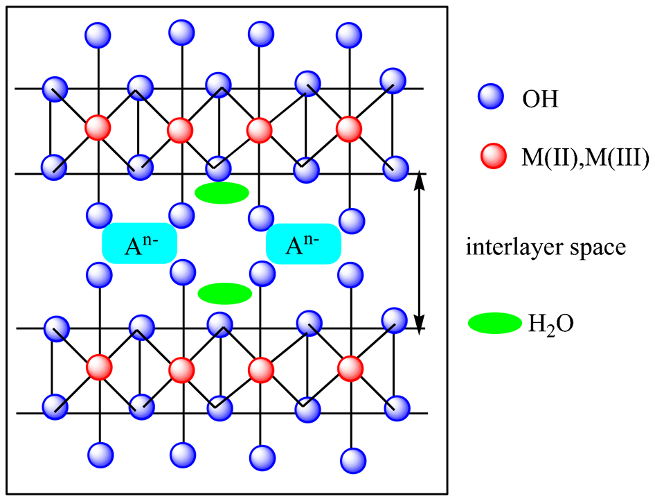
Schematic representation of Brucite LDHs
anion exchange ability in the interlayer
cation exchange ability in the Brucite-like layer
In Brucite structure, Mg2+ is surrounded by six hydroxyl groups in an octahedral co-ordination and these octahedra are connected through edge sharing to form inner sheets. These inner sheets are stacked upon one another to give layered network held through hydrogen bonds.
The coprecipitation preparation method of Brucite type of LDHs formation may conform to the process shown in Fig. 2 and the corresponding reaction schemes for the synthesis of all LDHs are summarised in Fig. 3. The mechanism of coprecipitation relies upon the condensation of hexagonal complexes in solution in order to build brucite-like layers having a uniform distribution of both metallic cations and solvated interlamellar anions. 15
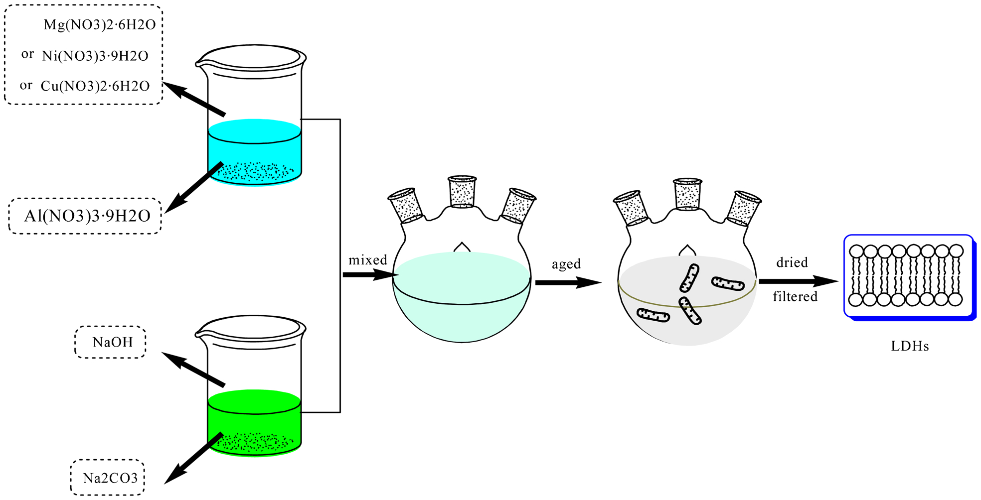
Schematic representation of formation process of Brucite LDHs
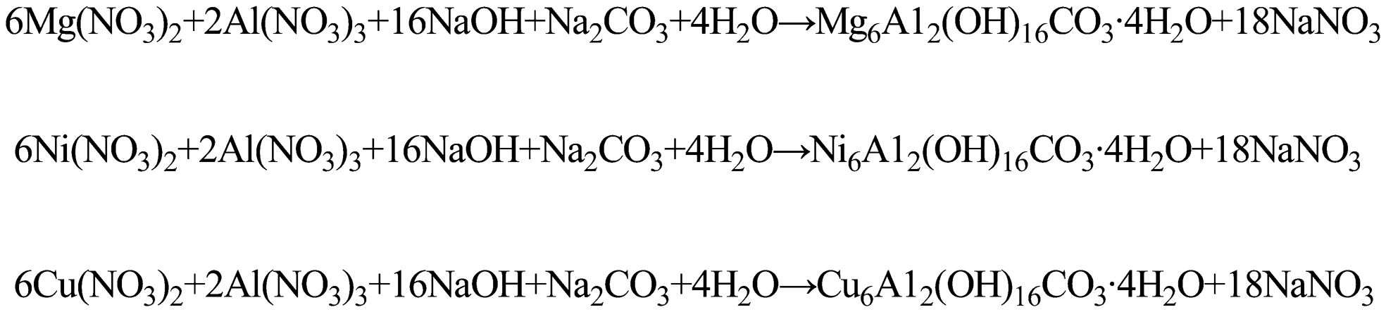
Reaction schemes for synthesis of all LDHs
As shown in Fig. 2, first, aqueous solutions of M2+ (Mg2+, Ni2+, or Cu2+) and M3+ (Al3+) containing the anion that is to be incorporated into the LDHs are used as precursors. Of the various (M(II)/M(III)) LDHs systems, some display a variable composition in terms of M(II)/M(III) ratio, while certain phases can be obtained only within a narrow range of ratios. Then, an aqueous solution containing precipitants was prepared. The precipitants, NaOH and Na2CO3, were used for this process. This solution of an alkali is added into the reactor simultaneously at such a rate as to maintain the pH at a selected value leading to the coprecipitation of the two metallic salts. Following coprecipitation, a thermal treatment process, that is, the conventional aging process is often performed in order to increase yields and/or the crystallinity of amorphous or badly crystallised materials. 16
FTIR
The FTIR spectra of the different LDHs are shown in Fig. 4. The antisymmetric OH stretching of the host layers and symmetric stretching of water molecules were observed for all the samples. The broad band at around 3500 cm−1 indicated the presence of the OH stretching modes, which may be the weak H bonding. This can be attributed to the vibrations of OH groups attached to Al, Mg, Ni, or Cu in the layers.
17
The H2O scissoring mode at around 1630 cm−1 provided the evidence of water molecules in the interlayer. A weak broad band at around 750 cm−1 may be due to the appearance of OH bending. In all cases the antisymmetric stretching mode (v3) of the
 species showed the position of around 1360 cm−1, as well as the in-plane bending mode at near 680 cm−1 can also provide the further evidence of a carbonate compound.
18
A sharp band at 450 cm−1 for all the samples showed metal–oxygen (Mg–O, Ni–O, or Cu–O) antisymmetric stretching in plane. It can provide the further evidence that substituting magnesium ions for nickel or copper ions led to the enhancement of charge density within the host-layers, and thereby strengthening the host-layers electrostatic interaction with guest interlayer.
19
species showed the position of around 1360 cm−1, as well as the in-plane bending mode at near 680 cm−1 can also provide the further evidence of a carbonate compound.
18
A sharp band at 450 cm−1 for all the samples showed metal–oxygen (Mg–O, Ni–O, or Cu–O) antisymmetric stretching in plane. It can provide the further evidence that substituting magnesium ions for nickel or copper ions led to the enhancement of charge density within the host-layers, and thereby strengthening the host-layers electrostatic interaction with guest interlayer.
19
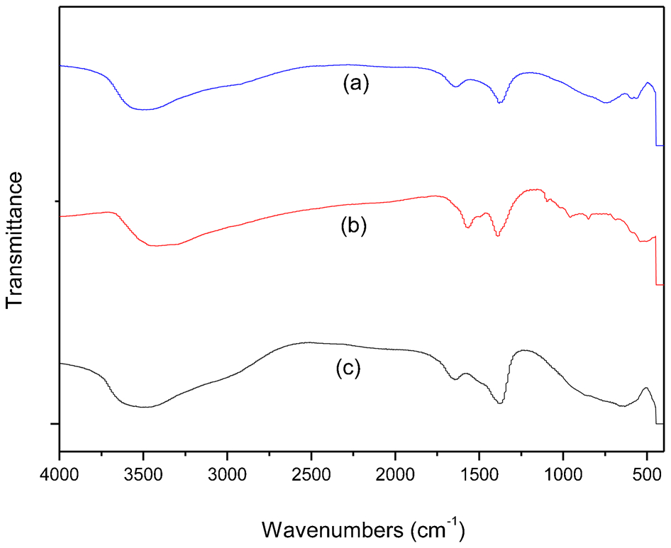
a Mg–Al; b Ni–Al; c Cu–Al
XRD
X-ray diffraction patterns of the different LDHs are shown in Fig. 5. The Mg–Al and Cu–Al LDHs showed the typical reflections of a pure well crystallised hydrotalcite, without any trace of other crystalline phases. Indexing of the diffraction peaks was done using standard Joint Committee on Powder Diffraction Standards (JCPDS) file 22-700. Clearly, the structural properties of the samples Mg–Al (Fig. 5a) gave a series of (001) peaks appearing as narrow symmetric lines at low angle, corresponding to the basal spacing and high order reflections. Parameters of the crystalline lattice determined from the position of diffraction lines 003 and the second basal reflection 006 of synthesised hydrotalcite equal to 0·8 and 0·4 nm. Such parameters are in accordance with the characteristics of hydrotalcites of the composition (1∶1) Mg2Al2(OH)12.CO3.nH2O.20, 21
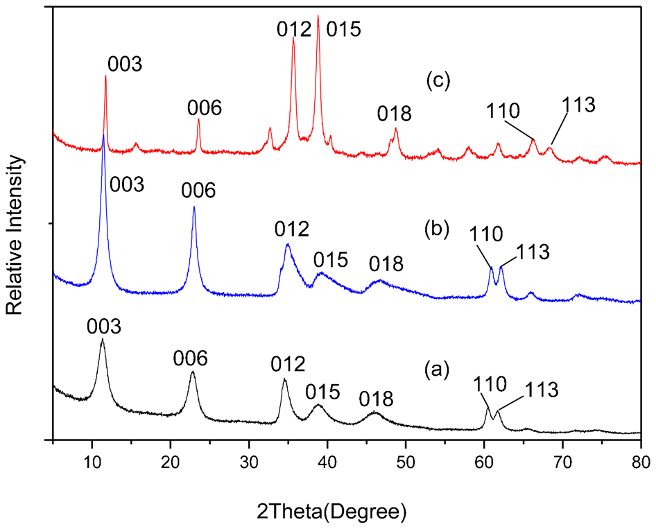
a Mg–Al; b Ni–Al; c Cu–Al
The XRD patterns of the Ni or Cu containing precursor (Fig. 5b and c) showed the diffraction lines of a well crystallised hydrotalcite-like phase (JCPDS 22-700) alone, suggesting that Ni2+ or Cu2+ was incorporated in the Mg2+ site and dispersed uniformly in the brucite layer of hydrotalcite-like structure. However, there was a difference in the intensities of peaks (b) and (c) from (a), indicating different degrees of crystallinity or structural order when the cationic composition varied. The intensities of the diffraction lines due to the hydrotalcite-like phase slightly increased by the addition of Ni or Cu cations, indicating that the crystallinity of the hydrotalcite-like phase in the Ni containing precursor, were higher than that of the Mg–Al–LDHs. Meanwhile, the substitution of the smaller magnesium ions for the bigger nickel or copper ions led to the increase in the average distance of metal ions within the host layers, thus lattice parameter and intensities may increase. In addition, charge density of the host layers decreased, thereby decreasing host-layers electrostatic interaction with guest interlayer, which resulted in interlay distance increasing.22, 23
TGA
The thermogravimetric profiles of different LDHs are shown in Fig. 6. The process of thermo-destruction for Mg–Al–LDHs had two stages (Fig. 6a). The first thermal effect observed at 100–260°C corresponded to the loss of the interlayer water, while the second at 260–600°C was to the destruction of the structure of the hydrotalcite like phase. The weight loss of Ni–Al–LDHs sample was almost the same as that of Mg–Al–LDHs (Fig. 6b), suggesting that two type of LDHs had almost the same structures. The first weight loss between 100 and 220°C was attributed to the loss of interlayer water, while the second was to the removal of host-layers hydroxyl and interlayer carbonate ions. In comparison with the weight loss of Mg–Al–LDHs, the final temperature of the weight loss for Ni–Al–LDHs obviously shifted towards low temperatures, indicating the decrease of host-layers electrostatic interaction with anions of guest interlayer. This was also confirmed by the shifts of the H2O scissoring mode and the characteristic modes of the
 towards larger wavenumbers in the FTIR spectra.24, 25
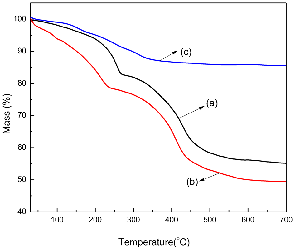
a Mg–Al; b Ni–Al; c Cu–Al
The thermal decomposition process of Cu–Al–LDHs could be described in two consecutive overlapped steps with a total weight loss of 13%. The first weight loss of 5% occurred between 40 and 200°C corresponding to the removal of water molecules physically adsorbed on the external surface of the crystallites. The second loss of 8% between 240 and 700°C was ascribed to the removal of interlayer water molecules, dehydroxylation, and decarbonation of the layers. Alejandre et al. 26 had found a similar thermal feature in an attempt to synthesise pure Cu–Al hydrotalcites and attributed this to differences in the coordination of carbonate anions within the brucite-like lattice.
SEM
The SEM image of the samples observation (Fig. 7) indicated clearly the different morphology of hydrotalcite. The colour, size, and dispersion of these particles were obviously affected by the different elements. These three kinds of LDHs presented white, yellow, and green colours, respectively. As shown in Fig. 7a, the surface of the plates, more or less even, shown by the Mg–Al hydrotalcite was preserved. It presented large grains attributed to inhomogeneously small particles (less than 1 μm). The micrographs of the Ni–Al hydroxycompounds studied in this work showed similar results. These small particles were distributed in the intergranular spaces left by the hydrotalcite grains. These images presented irregular particles assembled very loosely forming a cloud-like network (Fig. 7b). In addition, it was observed that the as synthesised sample, Fig. 7c, had bigger sheets, and the construction of as synthesised sample became more loose than usual. Also, the sheets became irregular, and the oxide agglomerated and formed to particles with irregular shape. These particles stacked each other with an irregular size of about 10 μm. The flat crystals were constituted by hexagonally shaped layers stacked in small groups. 27
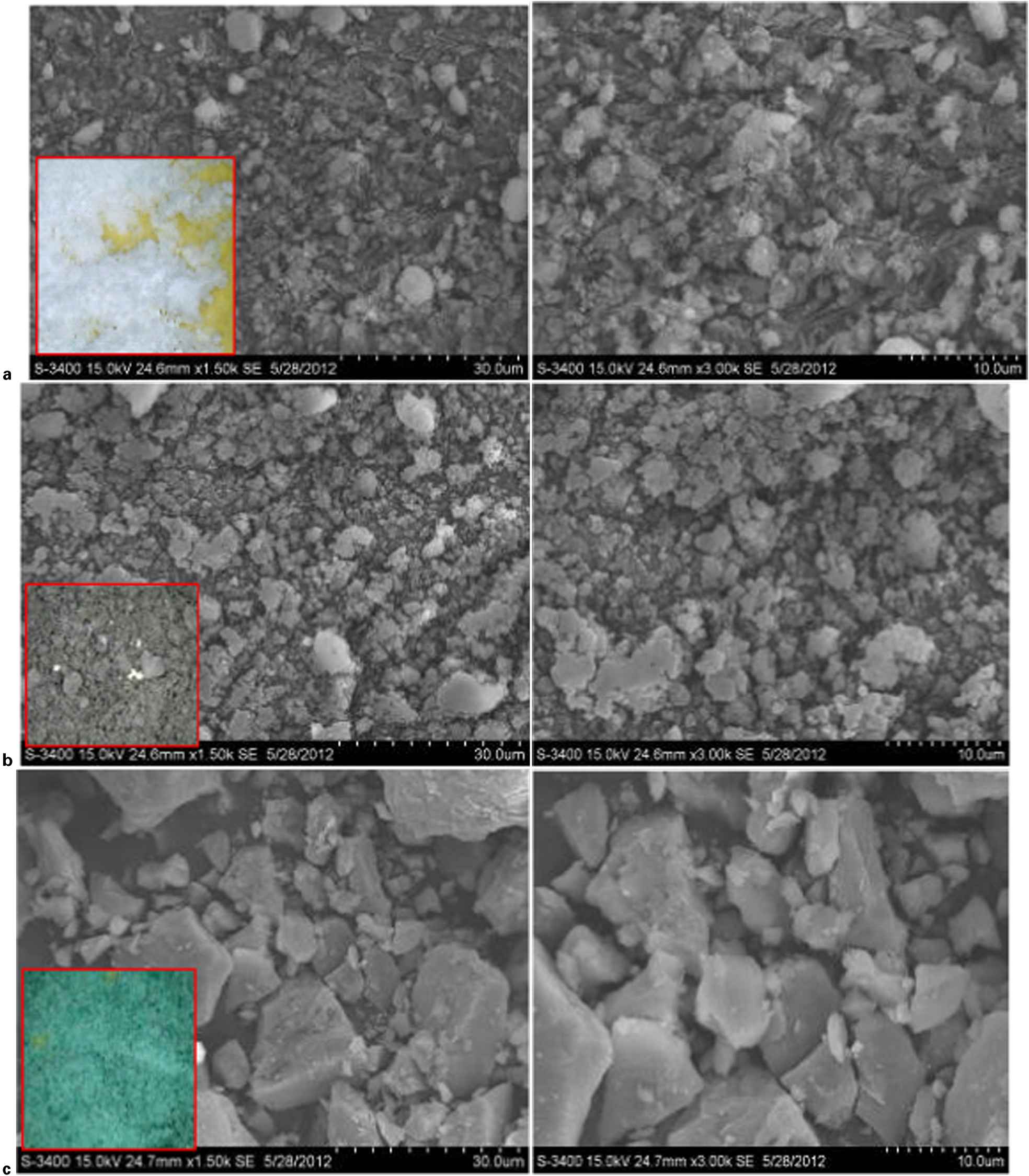
a Mg–Al; b Ni–Al; c Cu–Al
Analysis of EPDM/Cu–Al–LDHs composites
The Cu–Al–LDHs with the highest thermal stability via TGA were chosen as the agents applied in EPDM composites.
Cure characteristics
The cure curves of different EPDM composites are shown in Fig. 8. The EPDM cross-linking in presence of filler seems highly perturbed. This is the only way to explain the lower final torque measured during the process. The curves were similar and the theoretical cross-linking time was about 30 min. The maximum torque (Mm) has some relationship with the cross-linking density of the composites. However, the maximum torque of most EPDM/Cu–Al–LDHs composites was relatively decreased in comparison with that of pure EPDM composites. Compared with the following mechanical properties of these composites, the torque had no relationship with this property. This may be resulted from the different sensitivity to the degree of clay dispersion in polymer matrix for the tensile strength and the maximum torque, and small clay stacks were probably responsible for these less than expected decreased results. 28 Meanwhile, the relatively increase of minimum torque (ML), which showed an increase of viscosity, can make the different EPDM composites not easier to process.
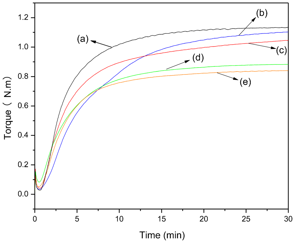
a EPDM; b EPDM/Cu–Al–LDHs-5; c EPDM/Cu–Al–LDHs-10; d EPDM/Cu–Al–LDHs-15; e EPDM/Cu–Al–LDHs-20
In addition, the data of other cure characteristics, such as t10 (scorch time, the time during which a rubber compound can be safely worked at a given temperature before curing begins in rubber manufacture) and t90 (optimum cure time, the time taken for the rubber to rise to its maximum point, and at 90% of this level) for different amounts of Cu–Al–LDHs filled EPDM systems were summarised in Table 2.
Cure characteristic of different EPDM systems at 170°C
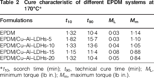
*t10, scorch time (min); t90, technical cure time (min); ML, minimum torque (lb in.); Mm, maximum torque (lb in.).
Scorch time is a parameter that is used to determine the safety of processing of rubber products. The longer the scorch time, the safer the processing. Compared with pure EPDM composite, it can be seen that the addition of 5–20 phr of Cu–Al–LDHs can increase scorch time (t10) and make processing safer.
Technical cure time is the shortest time that is used for the rubber to reach the maximum cross-linking degree during vulcanisation process. It can be deduced from the longer technical cure time (t90) that more energy was used in the cure process after the addition of different amount of LDHs.
Mechanical properties
The tensile strength and elongation at break of these EPDM/Cu–Al–LDHs composites showed different trend (Fig. 9). The tensile strength of these composites showed no remarkable changes compared with that of pure EPDM composite. However, the elongation at break also showed a remarkable decrease. The worst elongation at break was obtained when 5 phr of Cu–Al–LDHs amount was added. This may be due to the aggregates of Cu–Al–LDHs in the composites. In addition, the elongation at break was increased when more Cu–Al–LDHs were added. The induced increase in the apparent degree of cross-linking was the reason for such an increase. 29
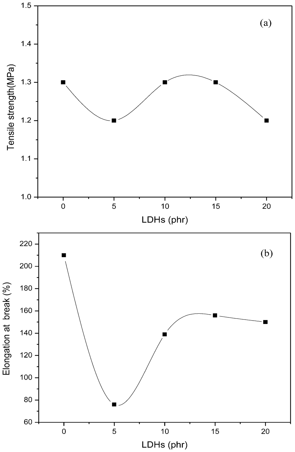
a tensile strength; b elongation at break
Wear resistant properties
Generally, wear resistance are thought to affect not only the performance, but also the life time of rubber products. The abrasion loss of the EPDM composites changed significantly with the addition of the Cu–Al–LDHs.
In this experiment, the abrasion was a kind of microcutting caused by the sanding between the grinding wheel of Akron machine and the soft rubber surface. This belonged to the line abrasion mechanism proposed by Burwell. 30 First, crack initiated in the rubber surface when the shearing force produced from friction exceeded the limited shearing strength the rubber could stand. Second, a tongue-like material was produced after the initiation of crack. Third, a tongue-like material ruptured and broke off the rubber matrix during the periodical friction, and thus the ridge-like morphology was developed.
Figure 10 presented the abrasion loss value of systems with the Cu–Al–LDHs. In the EPDM with 5–20 phr of Cu–Al–LDHs, the loss value showed a strong reduction by the increase of LDHs up to 10 phr. The abrasion loss of the composite EPDM/Cu–Al–LDHs-10 was 0·31 cm3, nearly 45% decrease, compared with the neat EPDM system, 0·56 cm3. However, due to the worse compatibility between EPDM and the aggregated silicate layers, the system showed worst wear resistant property after the addition of 20 phr of Cu–Al–LDHs. The abrasion loss of EPDM/Cu–Al–LDHs-20 was 0·61 cm3, about 9% increase.
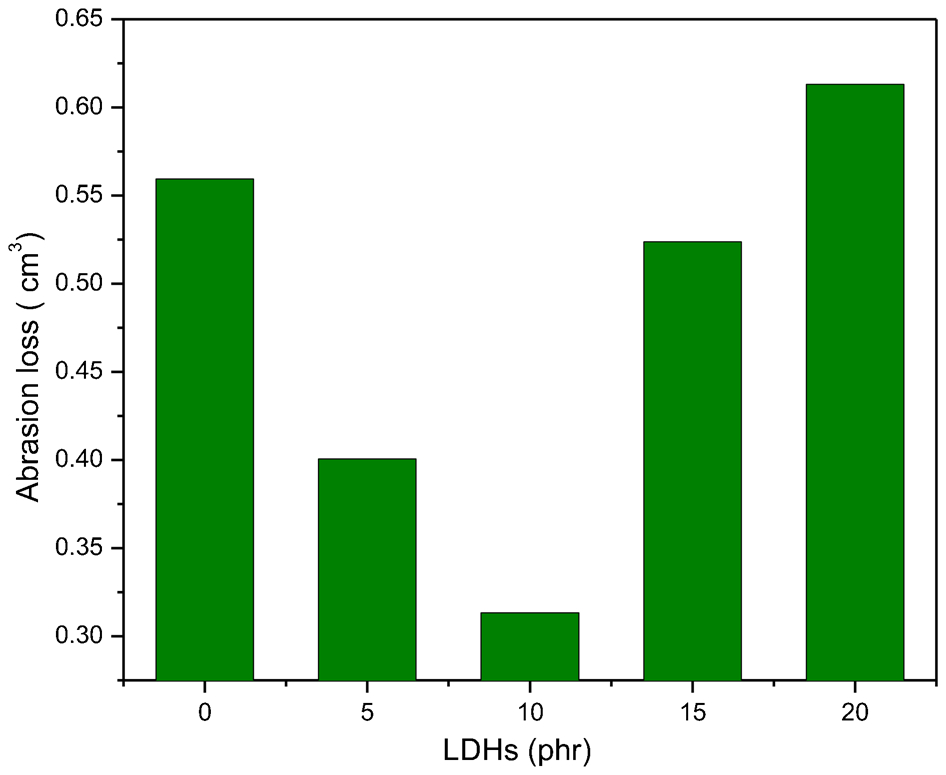
Abrasion loss of different EPDM composites
Thermal stability
In order to compare their thermal stabilities clearly, three parameters were measured from the TGA curves (Fig. 11), that is, the onset temperature of thermal degradation (Tonset, the temperature at which weight loss is 5 wt-%), the centre temperature of thermal degradation (Tmax, the temperature at which weight loss is the fastest), and the yield of charred residue at 600°C. 31
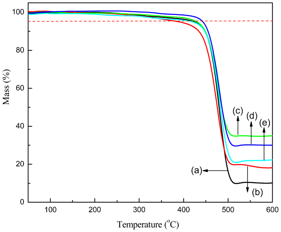
a EPDM; b EPDM/Cu–Al–LDHs-5; c EPDM/Cu–Al–LDHs-10; d EPDM/ Cu–Al–LDHs-15; e EPDM/Cu–Al–LDHs-20
Overall, the thermal stability of EPDM/Cu–Al–LDHs composites was almost better than that of EPDM (Table 3). At loading of 10 or 15 wt-% of Cu–Al–LDHs, Tonset and Tmax was about 450 and 480°C, respectively, 10 and 5°C higher than that of pure EPDM.
Thermogravimetric analysis results for thermal degradation of different EPDM composites
The well dispersed silicate layers not only hindered the evaporation of decomposition products but more effectively hindered the access of oxygen to the polymer, reducing the rate of initiation of polymer chain scission to produce volatile small products. The high decomposition temperature indicated the improved thermal stability of the composites. However, it is not so obvious that all these composites delivered the best thermal stability. For example EPDM with 5 phr of Cu–Al–LDHs had lower onset and centre degradation temperatures compared with that of pure EPDM. This was mainly attributed to the increased porous and damaged structure caused by the aggregates of Cu–Al–LDHs in the composites.
Flame-retardant performance
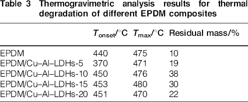
Due to the lack of excellent flame retardant effect, the UL-94 levels such as V-0, V-1 and V-2 levels of all samples cannot be obtained. The parameter t1 was recorded in this experiment. The vertical burning time t1 of EPDM/Cu–Al–LDHs systems are shown in Fig. 12. The burning time value of pure EPDM was relatively lower (235 s). By adding 5–20 phr of Cu–Al–LDHs into pure EPDM, the burning time value was improved about 53%. The EPDM/Cu–Al–LDHs-10 showed a longer burning time, 360 s, due to the flame inhibition effect of Cu–Al–LDHs. However, with addition of 20 phr of Cu–Al–LDHs into EPDM, these composites showed a decreased burning time, 205 s. This was probably due to the damaged structure and the resulted more holes, which were beneficial for the oxygen to flow into and helpful to the burning behaviour of these composites. 32
Vertical burning time of different EPDM composites
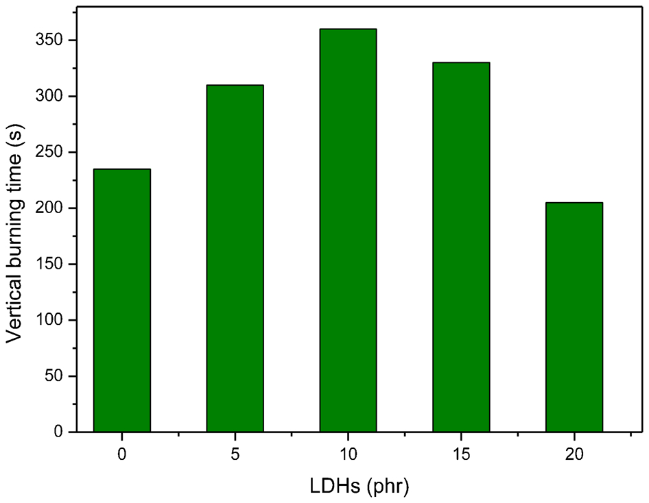
The photos were the images of vertical burning tests for the typical EPDM composites (Fig. 13). As can be seen, EPDM was easily flammable (Fig. 13a) and the EPDM/Cu–Al–LDHs composites can also be ignited. With addition of 10 phr of Cu–Al–LDHs, Fig. 13b, it showed better fire protection for EPDM. We can see that the fire of it was smaller after being ignited. The char layer was relatively thicker compared with that of pure EPDM. This was probably due to the high thermal stability of Cu and Al elements in the composites. In addition, the fire became more intensive as can be seen from the vertical burning image of EPDM/Cu–Al–LDHs-20 (Fig. 13c).
a EPDM; b EPDM/Cu–Al–LDHs-10; c EPDM/Cu–Al–LDHs-20
Regarding the improvement of flame-retardant performance for EPDM/Cu–Al–LDHs composites, we may explain that the carbonaceous layers that formed during burning had great effect on the fire-retardant properties. In all, the EPDM system containing Cu–Al–LDHs may have following flame-retardant mechanism. First, CuO and Al2O3 may be produced from the degradation product of Cu–Al–LDHs, and they may cover over the surface of EPDM which can inhibit the further combustion of the polymeric matrix (Fig. 14a). Second, LDH may act as a catalyst to facilitate the production of aromatic compounds and carbonaceous layers from the degradation products of methylene groups in EPDM (Fig. 14b). Char or coke then can be produced from these materials by hydrogen transfer reaction. They can act as a physical barrier and prevent combustible gases from feeding the flame, and also separate oxygen from the burning material. 33
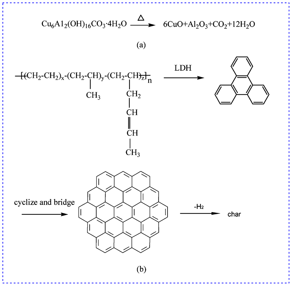
Flame-retardant mechanism of Cu-Al-LDH in EPDM composites.
Conclusions
In this work, different LDHs were prepared by coprecipitation method. The morphology, structure, and properties of these agents were analysed by FTIR, SEM, XRD, and TGA. These studies indicated structural transformations and phases formed of pure hydrotalcite with uniform size, which was porous and well crystallised. The thermal properties of the as synthesised sample were consistent with the inherent structure of hydrotalcite.
In addition, Cu–Al–LDHs were selected and effective for improving the mechanical and flame-retardant properties of EPDM composites. Experimental results demonstrated that incorporation of Cu–Al–LDHs into neat EPDM system had no obvious influence on the tensile strength and elongation at break. Meanwhile, the abrasion loss of EPDM/Cu–Al–LDHs-10 was 0·31 cm3, nearly 45% decrease, compared with the neat EPDM system, 0·56 cm3. Moreover, with the addition of 10 phr of Cu–Al–LDHs into EPDM system, the vertical burning time was increased from 235 to 360 s, almost 53% increase.
The mechanism for flame-retardant ability of Cu–Al–LDHs was proposed. Carbonaceous layers developed from silicate layers which could inhibit the pyrolysis degree of the rubber systems, and thus improve the flame-retardant behaviour for EPDM matrix.
Footnotes
Acknowledgements
This work was financially supported by National Natural Science Funds (Project No. 51173102), ‘Shu Guang’ project (Project No. 10SG53) supported by Shanghai Municipal Education Commission and Shanghai Education Development Foundation, Shanghai Talent Development Fund (Project (2012) No. 23), Construction of Innovative Team on Natural source of pharmaceutical engineering Project (Project No. XKCZ1205), Capacity-building of Local University Project by Science and Technology Commission of Shanghai Municipality (Project No. 11490501500), and Students Research and Training Project of Shanghai University of Engineering Science (Project No. cx1204001, No. cs1204007 and No. cy1204003).