
Abstract
This work aims to investigate how some significant atomising parameters influence the mass median particle size d50 of water atomised metal powders. More specifically, these were water pressure, melt flowrate, water jet angle, liquid metal viscosity and surface tension. Existing models for the prediction of d50 during water atomisation were reviewed. The selected models were fitted and compared with atomising experiments of liquid iron containing 0·5–4·4%C. Experimental results and model calculations were used in a parameter study to investigate how the different parameters influenced d50. The effect on d50 was large for the water pressure, medium for the viscosity and low for the melt flowrate and surface tension. Model calculations indicate that the jet angle has a large effect on d50, which should be verified by additional studies. The model proposed by Bergquist (B. Bergquist: Powder Metall., 1999,
List of symbols
apparent density/g cm−3
mass median particle size of as atomised powder/μm
diameter of liquid metal stream/m
model constant
mass flowrate of liquid metal/ kg s−1
mass flowrate of water/kg s−1
density of liquid metal/kg m−3
index used to relate the dependence of water pressure to d50
water pressure/Pa
water velocity/m s−1
jet angle between the axis of the water jet and axis of the metal stream/°
surface tension of liquid metal/N m−1
viscosity of liquid metal/Pa s
viscosity of atomising water/Pa s
density of atomising water/kg m−3
standard deviation for the log normal distribution
Introduction
Water atomisation of metal powders is a well established process, which can be used to produce many different products for a large number of applications. Moreover, a wide range of particle sizes can be produced by the process. More specifically, the most classical example probably is the production of water atomised iron powder for the powder metallurgy (PM) and welding industries.1 The PM grades with an as atomised particle size distribution containing 30–40% below 45 μm are here atomised at a water pressure of about 10–12 MPa and at steel flowrates between 75 and 500 kg min−1. Another application for water atomised powders is the component produced by metal injection moulding.2 Ultrahigh water pressures up to 150 MPa are here used to produce metal injection moulding powders with a mass median particle size d50 of ∼10 μm.
The water nozzles used in water atomisation are either in the form of discrete multiple nozzles or an annular slit concentric to the metal stream.3 Annular and V shaped jet geometries are generally used, and ‘free fall configurations’ is the most common design. The liquid metal is here poured through a tundish nozzle, from where the liquid metal stream falls under gravity into a system of water jets.
In an early study by Gummeson,4 it was pointed out that several variables affect the particle size during water atomisation, such as water pressure, diameter of the liquid metal stream, angle of the water jets, liquid metal viscosity and surface tension. Several studies5– 8 have shown that the pressure of the atomising water has a very large effect on the atomised particle size. This was illustrated in a study by Ankus and Venter,8 who increased the water pressure from 17·2 to 33·8 MPa during the atomisation of silver in a V jet laboratory atomiser. The increased water pressure decreased d50 from 102 to 40 μm. These tests were carried out at a superheat of 75°C above the liquidus temperature for silver. Further tests in this study were concentrated to investigate how d50 was influenced by a raised superheat. It was seen that this parameter had less effect on d50 than the water pressure. The mass median particle size decreased between 25 and 38%, depending on the water pressure, when the superheat was raised from 75 to 430°C. These results were confirmed by Dunkley and Palmer,6 who concluded that d50 decreases by about 5–10% per 100°C of superheat for alloys with a melting point above 500°C.
Bergquist9 alloyed liquid iron with sulphur to investigate how a decreased surface tension of the liquid metal influenced the particle size for water atomised iron powder. Sulphur contents up to 0·20% had a small effect on the particle size. However, it was estimated that a sulphur content of 1·5%S reduced d50 by 22% compared to pure liquid iron. In a study by Wang et al.,10 it was seen that d50 was affected by the dissolved carbon content in liquid iron. Water atomising tests were performed between 0·1 and 0·4%C, where d50 had a minimum value at ∼0·2%C. It was briefly discussed that this could be related to a minimum value for the viscosity and surface tension of liquid iron at carbon contents of about 0·1–0·3%C.
The purpose of this study is to investigate and evaluate how some significant parameters influence the as atomised mass median particle size during water atomisation. More specifically, these were water pressure, melt flowrate, water jet angle, liquid metal viscosity and surface tension. The first part of the study is a review of existing models for the prediction of the particle size during water atomisation. The selected models are then fit and compared to experimental results. The final part of the work is a parameter study, where it is investigated how d50 is influenced by different atomising parameters. This part includes both results from laboratory experiments and calculated d50 values from selected models.
Models for prediction of particle size
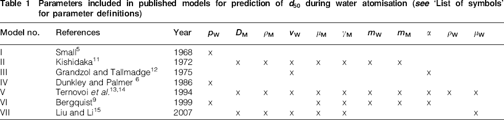
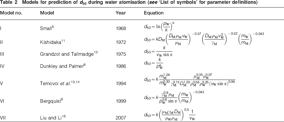
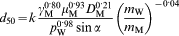
Careful control of the as atomised particle size distribution is necessary to produce water atomised metal powders with high quality and at low production cost. Therefore, it is important to have substantial knowledge of the relation between operational parameters and particle size to be able to produce water atomised metal powders with consistent and high yields. Table 1 summarises the published studies, which have modelled the relation between the mass median particle size d50 and the operational parameters during water atomisation. More specifically, these variables are water pressure pW, diameter of liquid metal stream DM, density of liquid metal ρM, water velocity vW, viscosity of liquid metal μM, surface tension of liquid metal γM, mass flowrate of water mW, mass flowrate of liquid metal mM, water jet angle α, density of atomising water ρW and viscosity of atomising water μW. The equations for each model are given in Table 2, and the intervals for the atomising parameters tested in these studies are presented in Table 3. In 1968, Small and Bruce5 studied the effect of atomising pressure during water and gas atomisation of a Stellite alloy. They found that the water pressure had the largest influence on the particle size and proposed an expression between d50 and the water pressure. Later, Kishidaka11 developed an equation that includes both Reynolds and Weber numbers for the liquid metal. The purpose was to simulate how viscous and surface tension forces affect the breakup of the liquid metal stream during atomisation. The model also includes the effect of an increased diameter of the liquid metal stream and a water to metal ratio term mW/mM. In 1975, Grandzol and Tallmadge12 studied how the water velocity and jet angle influenced the particle size. It was seen that the mass median particle size for a low alloyed steel powder decreased from 91 to 64 μm by increasing the jet angle from 15 to 30°. The water pressure had a constant value of 3·8 MPa during these tests. It was proposed that the velocity component vW sin α normal to the metal stream is responsible for the atomisation.
Parameters included in published models for prediction of d50 during water atomisation (see ‘List of symbols’ for parameter definitions)
Models for prediction of d50 during water atomisation (see ‘List of symbols’ for parameter definitions)
Intervals for different atomising parameters used in previous and present works (see ‘List of symbols’ for parameter definitions)*
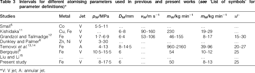
*V: V jet; A: annular jet.
Almost a decade later, Dunkley and Palmer6 derived a useful practical relation between the water pressure and d50 (Table 2). Here, it was found that n typically takes values between 0·7 and 1·2 for flat jets and that the proportionality constant k depends on the atomising parameters and liquid metal properties. In 1994, Ternovoi and Nichiporenko13 developed a mathematical model for annular jets, which included many parameters relevant to water atomisation. Final verifying tests were carried out for tool steels, after which the model was slightly modified to the formula14 given in Table 2. Five years later, Bergquist9 carried out water atomising tests in an atomiser with four individual flat jets at Höganäs AB (Fig. 1). A model for d50 was developed based on atomising test results for iron powder at different water pressures, superheats and dissolved sulphur contents in the steel. Finally, in 2007, Liu and Li15 developed a universal equation for d50 on an approach based on dimensionless numbers. A special model was proposed for water atomisation, but this equation was not verified with experimental data.
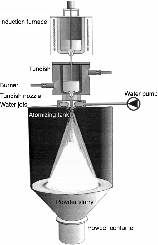
Experimental set-up used in this work and by Bergquist9
Experimental
Experimental facility
The atomising experiments were performed in a V jet laboratory water atomiser equipped with a high frequency induction furnace (Fig. 1). Around 12 kg of iron and graphite was melted in an alumina crucible in the furnace. The liquid steel temperature in the crucible was continuously measured by a thermocouple placed in a molybdenum zirconia stopper rod. When the target steel temperature for atomisation was reached, the liquid metal was bottom tapped through an 8 mm large nozzle into a clay graphite tundish. Liquefied petroleum gas burners were used to preheat the tundish, which was red hot when the atomisation was started. The liquid iron was poured through a 6 mm tundish nozzle into a V jet water atomising system. The V jet has in total four water nozzles, including two pairs of side and main jets respectively. The jet angle between the water jet and the metal stream was 25° for the main jets and 15° for the side jets. A constant total water flowrate of 50 L min−1 was used during all the tests. The water pressure was changed by using different combinations of water nozzles for the main and side jets respectively. The relation between the water flowrate in the side and main jets was constant in this study. Nitrogen was used to flush the atomising tank to avoid the risk for hydrogen explosions. Atomised powder was collected after settling for 1 h in the atomising tank. Finally, the wet powder was dried in a vacuum furnace for 13 h at 110°C.
Experimental programme and procedure
Five initial trials were carried out with decreased carbon contents in the steel from 4·4 to 0·5%C at a water pressure of 17·5 MPa (Table 4). The superheat was maintained at ∼200°C for these heats. The superheat is here defined as the difference between the liquid steel temperature in the induction furnace just before the start of atomisation and the liquidus temperature for the specific alloy. Six additional trials were thereafter performed to study how the particle size was influenced by a decreased water pressure and a raised superheat (Table 5). Liquid iron containing 4·7%C was initially atomised at water pressures from 13·5 to 8 MPa. These tests were followed by three heats at 17·5 MPa and 4·5%C, where the superheat was increased up to 500°C. The software Thermocalc16 was used to estimate the liquidus temperature for all the test heats in this work. The calculated values are given in Tables 4 and 5.
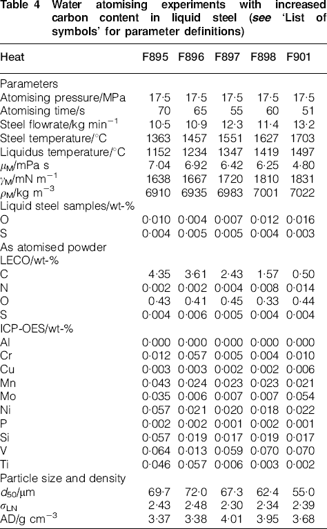
Water atomising experiments with increased carbon content in liquid steel (see ‘List of symbols’ for parameter definitions)
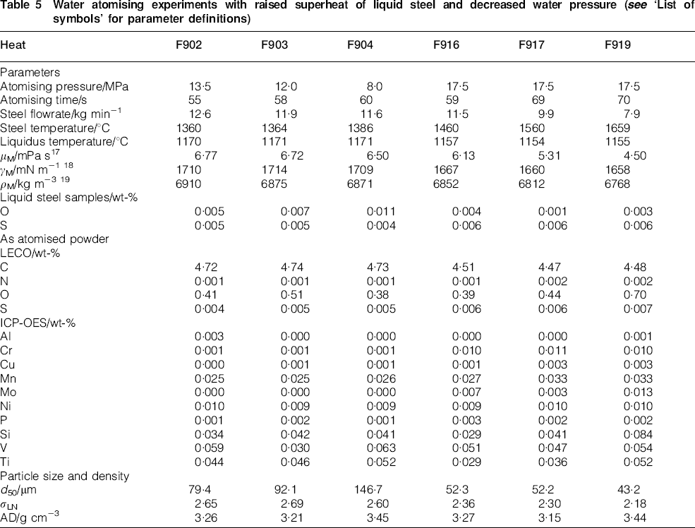
Water atomising experiments with raised superheat of liquid steel and decreased water pressure (see ‘List of symbols’ for parameter definitions)
Melt samples were taken with a quartz tube in the induction furnace just before the liquid steel was poured into the tundish to estimate the percentages of O and S in the steel before atomisation. Powder samples were prepared by a spinning riffler, where all the as atomised powders from each heat were split to the specific amounts needed for each analysis. A LECO analysis was used to determine the carbon, sulphur, oxygen and nitrogen contents according to ISO 15350 (percentage of C and S) and ISO 15351 (percentages of O and N). Trace elements were determined by inductively coupled plasma atomic emission spectroscopy according to ISO 13898-1–4 (1997), where a microwave assisted digestion method was used for the sample preparation. The as atomised particle size was analysed with sieve analysis (EN ISO 24497). The AD was determined with a Hall flowmeter (ISO 3923-1). The powder particle shape and morphology were investigated with a scanning electron microscope (SEM).
Results and discussion
As mentioned earlier, this paper has two objectives. In the initial part, the selected models for the prediction of d50 for water atomised metal powders are fit and compared to experimental data. These models are thereafter used together with the experimental results in a parameter study, where it is studied how significant operational variables affect the as atomised particle size. Models II, V, VI and VII were evaluated in more detail and compared with experimental data (Table 2). Models I, III and IV were excluded since these models only consider parameters of the water jet and not properties of the liquid metal. The values for d50 were calculated by curve fitting of data from a sieve analysis against the log normal distribution. It has been shown that this distribution is a useful tool to characterise the cumulative particle size distribution of as atomised metal powders. 6 6,17 The correlation between the log normal distribution and the cumulative particle size distribution obtained from sieve analysis was very good for all the experiments in the present study (Fig. 2). Investigation in SEM showed that the atomised powders in this work contained irregular, rounded and almost spherical particles. It was also noticed that the heats atomised at higher carbon contents seemed to have a larger amount of rounded and spherical particles (cf. Figure 3 Figs. 3 and 4).
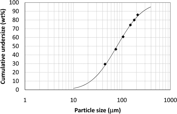
Curve fitting of as atomised sieve analysis against log normal distribution, heat F902, liquid iron alloyed with 4·72%C, water pressure 13·5 MPa
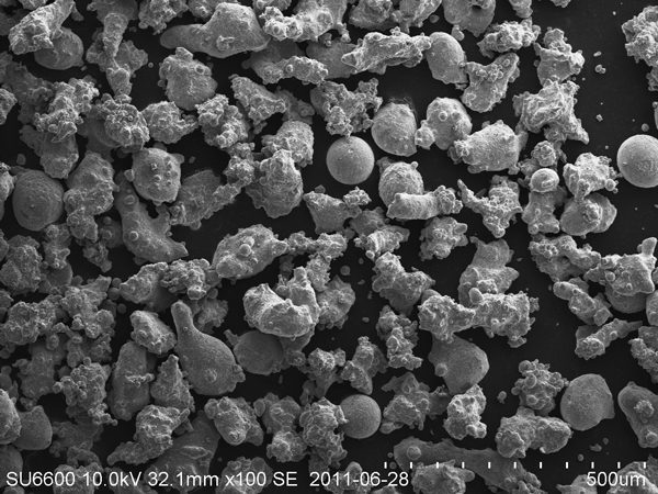
Scanning electron microscopy investigation, heat F901, 0·50%C, particle size of 75–106 μm
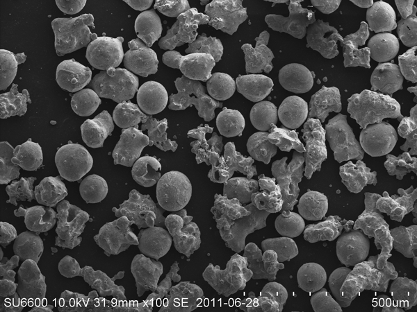
Scanning electron microscopy investigation, heat F895, 4·35%C, particle size of 75–106 μm
Oxygen and sulphur are strong surfactants, and small amounts of these elements can have a significant effect on the surface tension of liquid iron. The sulphur and oxygen contents were therefore analysed in samples taken in the liquid steel just before atomisation (Tables 4 and 5). The oxygen content was measured between 10 and 160 ppm, depending on %C and degree of superheat. Sulphur varied between 30 and 60 ppm. A detailed LECO analysis of the oxygen content in as atomised powder was also performed for heat F895 and F919. The power input to the LECO analyser was increased in five steps to estimate at which temperature the oxygen was released from the samples. Figure 5 shows the relative concentration of CO (g) at different temperatures for heat F895. The total oxygen content (84%) was released already at 1000°C, and 12% at 1160°C. A very similar result was obtained for heat F919. These results, together with the relatively low oxygen contents in the melt samples, indicate that the major part of the oxygen is located as iron oxides at the surface of the particles.
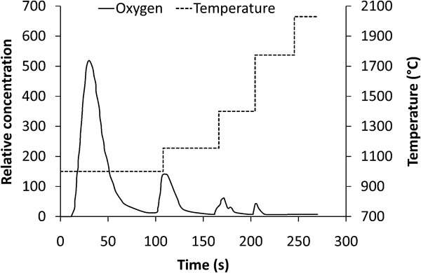
Relative oxygen concentration released as CO (g) at different temperatures, TC-436 LECO analyser, heat F895, total oxygen released as 0·40%CO and 0·03%CO2
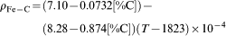
Estimations of liquid metal viscosity, surface tension and density are summarised in Tables 4 and 5. It was here assumed that the temperature loss between the induction furnace and the tundish nozzle was 100°C for all the heats. Viscosity data were estimated from a study of the Fe–C system by Krieger.18 In addition, values for the surface tension were taken from a review by Keene,19 who has summarised the data for binary iron alloys. The surface tension was estimated with data from Tszin-Tan et al.
20 at %C below 2·3, while the values from Nizhenko and Floka21 were used at higher carbon contents. The temperature of the atomising water was assumed to be 20°C in the calculations, which gives water density and viscosity of 0·998 g cm−3 and 1·00 mPa s respectively. The density of liquid iron was calculated using equation (1) developed by Jimbo and Cramb22
Models II, V and VII contain a term for the water velocity instead of the water pressure (Table 2). Therefore, equation (2)12 was used to relate the water velocity to the water pressure

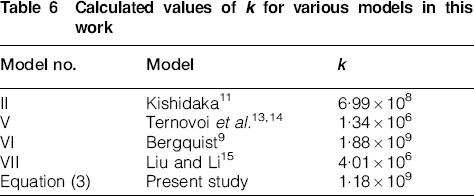
The constant k in models II, V, VI and VII was calculated with the least square method using data from heat F895-901 (Table 4). The parameter units defined in ‘List of symbols’ were used to calculate k. The determined values of k are given in Table 6. These k values were then used for all the calculations in this study. A comparison between experimental and calculated values of d50 is given in Fig. 6. The 1∶1 line represents here a perfect correlation between calculated and experimental d50 values. Models II, VI and VII show a relatively good agreement with experimental data. However, a poor correlation is seen for model V.
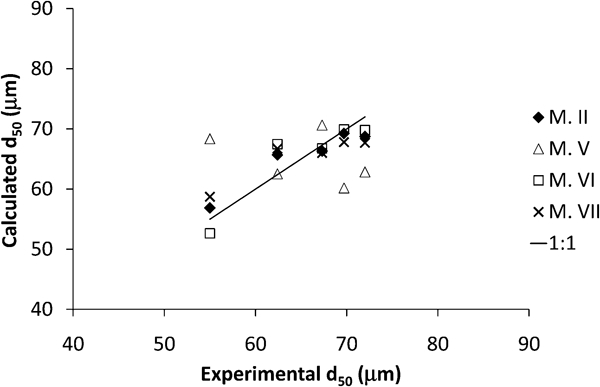
Calculated and experimental d50 values for various models: heat F895-901
Calculated values of k for various models in this work
Influence of water pressure
Water atomising experiments of liquid iron alloyed with 4·4–4·7%C were used to further compare the selected models. The water pressure was varied between 8 and 17·5 MPa during these tests. Figure 7 shows the relation between the water pressure and the d50 values for experimental heats and model calculations. Model VI shows the best agreement with the experimental results, but all the models predict too low d50 values at low water pressures. In addition, the calculated values for model V have a relatively large scatter compared to the other models. A deeper evaluation shows that the melt flowrate has a very large influence on d50 for model V. The heats in Fig. 7 had a variation of the melt flowrate between 10·5 and 12·6 kg min−1. This corresponds to an increase in d50 by 1% for models II and VI if all the other parameters are held constant. A similar calculation for model V gives an increase in d50 by 25%, which seems unrealistic. This explains to a large extent the scatter and poor correlation to experimental data seen for model V in Figure 6 Figs. 6 and 7.
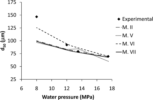
Comparison of experimental and predicted d50 for various models as function of water pressure: atomisation of liquid iron alloyed with 4·4–4·7%C
The effect of water pressure on d50 in Fig. 7 can be discussed by using model IV proposed by Dunkley and Palmer.6 The exponent n is here a measure of the pressure dependence for a given atomiser and system. A regression analysis for the experimental data in Fig. 7 gives n = 1·0, which is within the interval of n = 0·7–1·2 normally reported for flat jets.6 An n value of 0·8 is suggested in model VI, whose predictions also show the best agreement with the current experimental data. If the water velocity vW is recalculated with equation (2) for models II, V and VII, then these models would get an equivalent n value of between 0·48 and 0·51. This explains why especially these models underestimate d50 at decreased water pressures compared to the experimental data in this study.
Influence of melt flowrate
The melt flowrate into the atomiser can vary during the atomisation, which can result in a variation of the particle size and a wider accumulated particle size distribution for the entire heat. The varying melt flowrate can be caused by several factors, like a changed height of liquid metal in the tundish, a wear of or freezing in the tundish nozzle and a different fluidity of the liquid metal. The particle size distribution can also be affected if the melt flowrate is increased to increase the capacity of the atomiser. The present study has only used a 6 mm tundish nozzle. It has thereby not been possible to experimentally determine how d50 is influenced by the melt flowrate. The selected models were therefore used to simulate how the particle size was influenced by an increased diameter of the liquid metal stream. The melt flowrate was estimated by using the value of 10·8 kg min−1 as a reference for a 6 mm tundish diameter. The melt flowrate for the other tundish diameters was also calculated by multiplying this reference melt flowrate with a corresponding change of the cross-sectional area of the liquid metal stream. All the models predict an increased particle size with an increased tundish diameter (Fig. 8). As seen in Table 2, model VI contains only a water to metal ratio term, which with the exponent −0·043 gives very moderate influence on d50 by changing the melt flowrate. In addition, model V results in a very large increase in d50 when the melt flowrate is increased. More specifically, this model predicts that d50 will increase from 36 to 81 μm by increasing the tundish diameter from 4 to 7 mm.
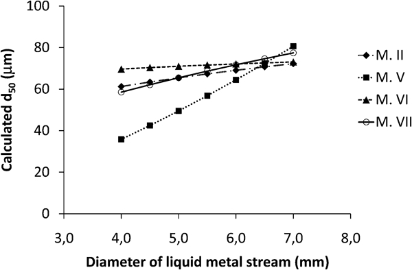
Calculation of d50 as function of liquid metal stream diameter for various models: water flowrate = 50 L min−1, pw = 12 MPa, α = 25°; alloy composition: Fe–0·5C, γM = 1834 mN m−1, μM = 4·9 mPa s, ρM = 7021 kg m−3
Influence of jet angle
The influence of jet angle on d50 was calculated for models V and VI, since a constant jet angle was used during all the experiments in this work. The use of the factor sin α in these models has its origin from model III developed by Grandzol and Tallmadge,12 where it is assumed that the velocity component normal to the liquid metal stream is responsible for the atomisation. For a 12 MPa water pressure, these models predict a large decrease in d50 at increased jet angles (Fig. 9). It can be speculated that a larger jet angle results in an increased transfer of energy from the water jet to the liquid metal, which decreases the as atomised particle size.
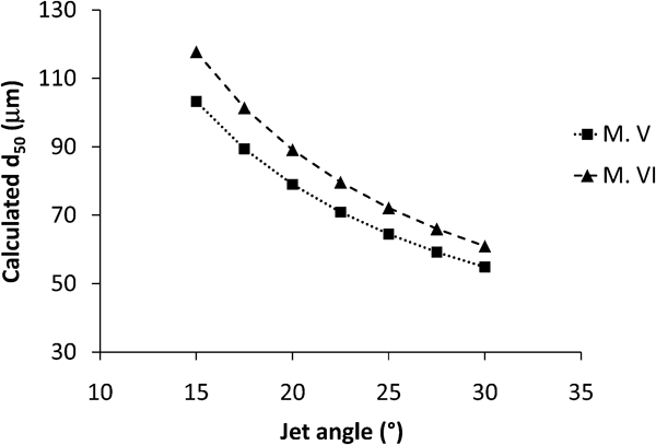
Calculation of d50 as function of jet angle for models V and VI: water flowrate = 50 L min−1, pw = 12 MPa, DM = 6 mm, mM = 10·8 kg min−1; alloy composition: Fe–0·5C, γM = 1834 mN m−1, μM = 4·9 mPa s, ρM = 7021 kg m−3
Influence of viscosity and surface tension
Atomising tests were also carried out to investigate how the liquid metal properties viscosity and surface tension influence the powder particle size. Trials were performed at various superheats and carbon contents at a water pressure of 17·5 MPa. Figure 10 shows the relation between d50 and the dynamic viscosity of liquid iron for experimental heats. The correlation is relatively good, where the particle size increases with an increased viscosity. A further analysis was made by calculating the influence of viscosity for the d50 models presented in this study. The calculations show a similar influence of viscosity on d50 as the experimental results (cf. Figure 10 Figs. 10 and 11). The best correlation between predicted and experimental results is obtained for model VI. The coefficient for μM in this model is 1·0, which is close to the value of 0·9 obtained by the regression analysis in Fig. 10.
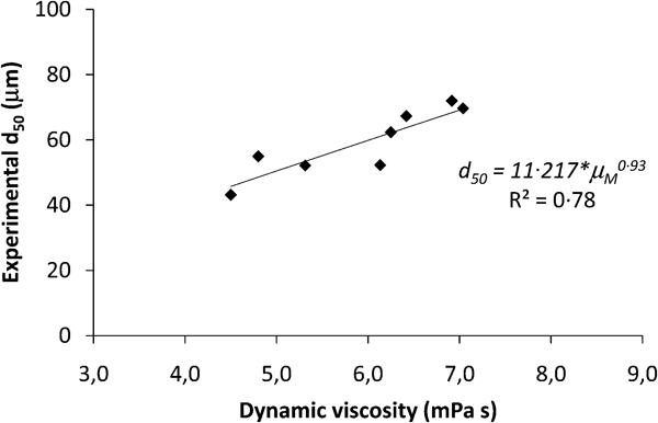
Relation between liquid metal viscosity and d50 for experimental heats atomised at water pressure of 17·5 MPa
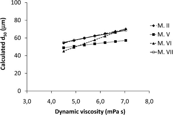
Calculation of d50 for various models as function of liquid metal viscosity: water flowrate = 50 L min−1, pw = 17·5 MPa, α = 25°, DM = 6 mm, ρM = 6835 kg m−3, γM = 1660 mN m−1 and mM = 10 kg min−1
No correlation was seen between the experimental d50 values and the surface tension for heats atomised at 17·5 MPa. Model calculations also predict a very small change of the particle size, within the interval that the surface tension was varied during these experiments (Fig. 12). This seems reasonable since an increased %C and melt temperature generally have a small effect on the surface tension for Fe–C alloys.19 It is therefore probable that the surface tension has to be varied more than in the current work to determine its actual effect on the particle size.
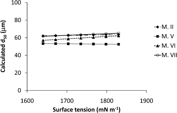
Calculation of d50 for various models as function of surface tension of liquid iron: water flowrate = 50 L min−1, pw = 17·5 MPa, α = 25°, DM = 6 mm, ρM = 6835 kg m−3, μM = 5·75 cP and mM = 10 kg min−1
However, it has to be pointed out that the results presented for the viscosity and surface tension in Figure 10 Figure 11 Figs. 10–12 will be seen as provisional and have to be verified by additional studies. This since measurements of both viscosity and surface tension data are difficult, which has resulted in a large scatter between published data for the system Fe–C. 19 19,23 In addition, the heats atomised at 17·5 MPa at various superheats and %C have a relatively large variation of the steel flowrate (Tables 4 and 5). This could to some extent have influenced the scatter for the data presented in Fig. 10.
Final discussion
The present study shows that mathematical modelling can be a useful tool to predict the as atomised particle size during water atomisation. Existing models in the literature today are mainly empirical, and further studies are recommended to describe the complex phenomena related to water atomisation. Model VI proposed by Bergquist9 showed in general the best agreement with the current experimental results. A modified expression based on this model is therefore proposed as
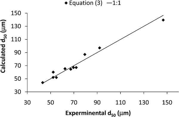
Calculated d50 values for equation (3) versus experimental data from present study
Conclusions
This work has focused on the particle size of the water atomised metal powders. Published models for prediction of d50 were fitted and compared with experimental data. Model calculations and atomising tests of Fe–C alloys were used to study how some important atomising parameters affect the particle size. The influence of water pressure and viscosity was investigated by both model calculations and atomising experiments. Model calculations were used to estimate the effect of jet angle, melt flowrate and surface tension. The influence on d50 was as follows for investigated parameters:
water pressure: large effect, 45–50% decrease for pressures from 8 to 17·5 MPa
jet angle: large effect, 45–50% for jet angles from 15 to 30°
viscosity: medium effect, 25–35% for viscosities from 7 to 4·5 mPa s
melt flowrate: small effect, 5–15% for tundish diameters from 7 to 4 mm
surface tension: small effect, 0–10% for surface tensions from 1830 to 1640 mN m−1.
The large estimated influence of the jet angle on d50 will be treated with care. This since its strong effect is only supported by the proposed models,9,12– 14 which are based on a limited amount of experimental data. In addition, the presented results in this study for the viscosity and surface tension will be seen as provisional. Careful additional studies are needed to describe their individual influence on the particle size. Model VI proposed by Bergquist9 showed in general the best agreement with the current experimental results. Additional studies are therefore recommended to further develop this model.
Footnotes
Acknowledgements
The authors wish to thank H. Tegefeldt, M. Augustsson, M. Ohlsson and L. Boo for all their assistance during the atomising experiments. Thanks are also given to P. Johansson for the support and help during the metallographic investigation. B. Kaplan and E. Hervestad are also acknowledged for their participation in the initial part of the study.