
Abstract
To date, the modelling of crack formation during the ejection stage in powder metallurgy die compaction processes has fallen outside the scope of conventional finite element studies on this process. In this paper, we attempt to make an exploratory step in this regard by presenting a case study that exemplifies how crack simulations can be harnessed to solve real powder metallurgy manufacturing problems. The part subjected to the study is a multilevel adapter whose design to production process proved problematic to the manufacturer, to the point that simplifications in the geometry of the part were to be made. The goal here is, through finite element simulations, to clarify the reasons behind the difficulties in ejecting free crack compacts, to understand the connection of such difficulties with the geometry modifications introduced in the design and to make recommendations on the prevention of similar problems in other situations.
Introduction
Cracking in green compacts is one the major quality problems experienced by the powder metallurgy (PM) industry; it is perhaps the bête noire of ferrous component manufactures. Cracks formed during pressing operation, due to the insufficient interparticle bonding, mass slippage, etc., can be prevented by devising pressing schedules that ensure a nearly uniform density distribution or at least avoid sharp density gradients. The density prediction ability of available finite element models can greatly assist the PM designer in this task, as shown for instance by Federzoni et al. 1 The first serious attempt to numerically model cracking in PM compaction, made by Coube and Riedel,2 and also most of the later proposals,3 have focused exclusively on the simulation of these ‘pressing’ cracks.
Very frequently, however, cracks in green compacts are not the manifestation of an inappropriate consolidation process, but rather the result of improper pressure release and/or ejection (from the die cavity) stages; the poor tensile properties of green parts render their structural integrity exquisitely vulnerable to tensile/shear stresses provoked by improper punch deflections or excessive elastic spring back.
In contrast to the modelling of ‘pressing’ cracks, the numerical study of cracking during pressure release and ejection in PM die compaction processes has been scarcely considered in the PM literature. Earlier attempts 4 4,5 to predict post-pressing failure focused on merely analysing the evolution of stresses throughout the part so as to detect excursions above a given stress threshold, but without giving any hint on crack propagation features, such as length, orientation, severity, etc. To actually model crack propagation, it is necessary to enrich the constitutive model with some means to capture the deterioration of strength experienced by the material after the attainment of the corresponding yield or fracture threshold, namely, a strain–stress softening law. The work by Jonsen et al. 6 stands as a landmark in this regard since it provides the first, to the authors’ knowledge, experimental measurements of fracture energy — an indispensable ingredient for the calibration of the aforementioned softening law — of consolidated iron based powder. In a subsequent paper by Jonsen and Haggblad,7 a fictitious crack model featuring a stress versus crack width relation dependent on fracture energy is proposed and successfully applied to reproduce cracking in a diametral compression test; however, no critical assessment of its performance in a real manufacturing scenario is carried out, nor are the theoretical formalisms behind the inescapable coupling between densification and cracking considered (the higher the density attained locally, the higher the strength and the toughness and hence the resistance to cracking). In two recent papers, 8 8,9 the present authors do address this coupling issue by elaborating a continuum plasticity framework that permits to describe these two conspicuously distinct phenomena (cracking and densification) in a thermodynamically sound, unified manner. A radically distinct approach to crack prediction in PM compacts, on the other hand, is adopted in the work of Rolland et al. 10 They address the problem in a probabilistic fashion: rather than treating the occurrence of cracks as a ‘deterministic’ event, Rolland et al. account for the inherent randomness and uncertainty of material parameters and tooling kinematics and use a failure risk model that enables one to identify and delimit areas of the part where cracks are likely to develop.
Despite these recent efforts to improve the cracking predictive ability of die compaction models, the topic remains still within the research arena, and crack simulation technology is not yet being exploited by the PM industry to tackle problems linked with cracking during ejection in die compaction processes. It is precisely the purpose of the present paper to attempt to make an exploratory step in this regard by presenting a detailed case study that exemplifies how crack simulations can be used to address real PM manufacturing problems. The finite element program used for this purpose has at its core the abovementioned constitutive model developed by the authors. 8 8,9 The part subjected to study is an axisymmetric, low height, multilevel adapter (Fig. 1) whose design to production process proved dramatically problematic, i.e. costly and time consuming, to the manufacturer: although almost every reasonable and technically realisable alternative was tried, it was not possible to find a single ejection procedure leading to free crack compacts. In order to obtain a reliable product, the manufacturer was finally compelled to abandon the fabrication of the part in its original form and agree with the client certain modifications, inconsequential to the functionality of the finished component, in the initial geometry. The result of these modifications is shown in Fig. 2; the abruptness of the cross-sectional change between the outermost levels is eliminated by a tapered surface. The goals of the present study are, by interpreting the outcome of finite element simulations of various, alternative ejection schemes (and admittedly with the advantage of hindsight), to throw some light on the possible reasons behind such difficulties; to understand their connection with the geometry modification introduced in the revised design; and on the basis of the insight gained from the computed results, to make recommendations on the prevention of similar problems in other situations. This case study will serve also to provide some useful guidelines and advises on the modelling of pressure release and ejection in computed numerically controlled (CNC) advanced press machines and on how computed results should be interpreted in order to arrive at an accurate diagnosis and avoid misleading claims regarding the adequacy of a given ejection route.
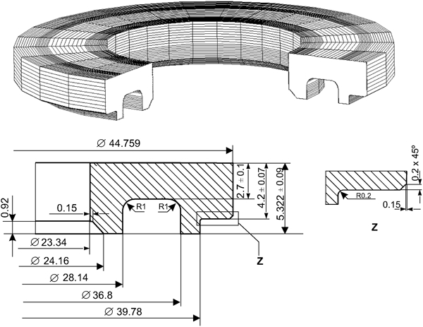
Geometry of part (dimensions in mm): axisymmetric geometry is revolved 270° for ease of visualisation
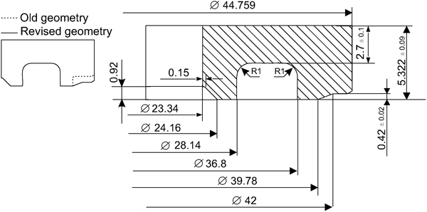
Revised geometry (dimensions in mm)
Preliminaries
Constitutive model
The powder constitutive model used for the computations is basically an extension and refinement, to cover also the description of material failure, of the classical isotropic, elastoplastic Drucker–Prager/Cap type model (Fig. 3). Strain history is encapsulated into two internal variables: a hardening variable ξs, which is taken approximately as the relative density ξs≈η, and a softening variable ξs associated with the accumulated (plastic) shear strain.
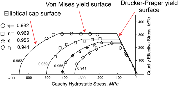
Experimental yield stress data (as function of relative density η) from consolidated and overconsolidated compression tests on Distaloy AE powder specimens,11 together with isodensity contours constructed using Drucker–Prager/Cap type criterion refined with density dependent von Mises yield surface
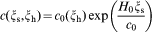
When the stress state remains on the Drucker–Prager yield surface during the interval of continued plastic loading, the internal softening variable increases its magnitude, causing, in turn, a decrease in the cohesion variable c, which is the intersection of the Drucker–Prager yield surface with the deviatoric axis. This cohesion variable can be regarded as a measure of the green strength of the compacting powder. The relationship between cohesion and internal softening variable is given by the following softening law
For further details on the theoretical basis of the employed constitutive model and its numerical implementation in a finite element code, the reader is referred to Hernandez et al. 8 8,9
Description of compacting press
The schematic of the CNC, multiplaten press machine employed for compacting the part is shown in Fig. 4a. In Fig. 4b, only those elements considered for modelling purposes are displayed: an upper punch (UP), four lower punches (LIP, LMP, LOP-I and LOP-II) (the acronyms LIP, LMP and LOP signify lower inner punch, lower middle punch and lower outer punch respectively), a die that controls the outer peripheral shape and a core rod that controls the inner peripheral shape and size of the part. The UP is mechanically driven during pressing but not during pressure release and ejection: a hydraulically controlled mechanism, inserted between the UP and the upper ram, allows independent movements during this stage. The lower punches labelled in Fig. 4b as LIP, LMP and LOP-I, as well as the die and the core rod, are mounted on separate platens operated by hydraulic cylinders placed on the stationary member of the press. The lower outer punch LOP-II, by contrast, cannot move independently, but rather is attached to the die table in a stepped die fashion.12
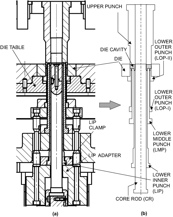
a cross-sectional view of compacting press and b geometric model of tooling items included in simulation
Powder and tooling properties
The powder employed in making the part is a Distaloy AE iron based powder with apparent density ρapp = 3·25 g cm−3. Material parameters can be obtained from the empirical adjustment presented by Hernández et al. 8 The fill density is assumed to be equal to the apparent density and uniform throughout the die cavity. The friction between the powder mass and the faces of the tool die walls and core rod is modelled via a friction Coulomb law with coefficient μ = 0·12. The isotropic, elastic behaviour of the tooling is characterised by a Young's modulus Etool = 210 GPa and a Poisson's ratio ν = 0·3.
Pressing stage
It needs no emphasis that the success in predicting numerically the formation of cracks during the post-pressing stages (pressing release and ejection) relies considerably on the quality of the density and the stress distributions computed at the end of the pressing stage. In a recent paper,13 the authors provide both an accurate description of the boundary and initial conditions for modelling the pressing of the concerned part and a critical assessment of the finite element results, using the abovementioned constitutive model, corresponding to this phase. Hence, here, we limit ourselves to show the computed density contours reported in such a paper (Fig. 5). The portion with the lowest density is located above the lower inner punch; in this case, the numerically predicted value is 0·10 g cm−3 below the experimental one, which is also the maximum discrepancy between the experiment and predicted density values.
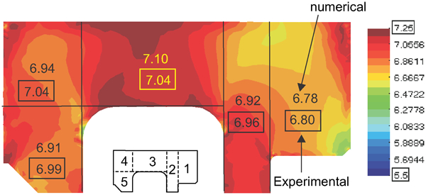
Contour plot of density computed at end of pressing stage
Ejection of original part
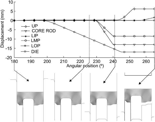
The ejection stage covers approximately the portion of compaction cycle ranging from 180° (end of pressing) to 265°, where the part is picked up by the gripper — note that the reciprocating motion of the upper ram is parametrised in terms of the angular position PHI of the main shaft. The ejection stage, in turn, can be subdivided into three distinctly different phases; this division is illustrated schematically in Fig. 6.
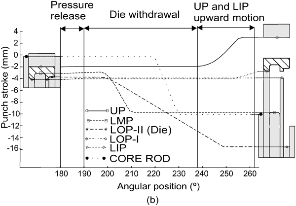
Typical tooling motion profile for ejection stage
The first phase corresponds to partial pressure release (from 180 to 190°), during which the UP moves slightly upward so as to reduce radial forces and facilitate the subsequent withdrawal of the die. In the second phase, approximately from 190 to 240°, the die moves downward (withdrawal tooling system), while the two lower punches (LIP and LOP-I) forming the lowest faces remain stationary so as to support the part. In the third stage, ranging from 240 to 265°, the UP moves up away from the compact, and simultaneously, the lower inner punch lifts the part slightly so that it can be removed by the gripper from the compaction zone. The finite element results shown in the sequel will be also presented according to this division of the process.
For illustrative purposes, a microscopic view of two of these observed cracks is shown in Fig. 7. It should be pointed out, however, that the ensuing discussion is not intended to set up a systematic comparison between experimentally recorded crack images and computed cohesion contours; the retrospective character of the study makes somewhat elusive such rigorous verification of results. Rather, we limit ourselves to qualitatively examining, by simple comparison of cohesion contours, the adequacy of alternative ejection processes.
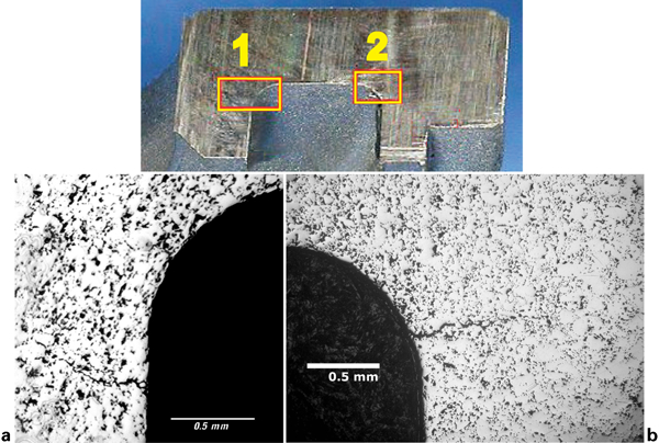
Cross-sectional view showing two cracks detected in green compact: microscopic images of a zone 1 and b zone 2
Pressure release
In the numerical simulation presented in the following, the UP is gradually lifted until the axial force on the UP is set to a hold down force of 10 tons.
In addition, in order to compensate for the unbalanced punch deflections, the lower inner punch LIP, which is the largest one, descends by 0·05 mm, whereas the lower outer punch LOP-I moves 0·04 mm upward. The LMP and die platens are kept fixed. Figure 8 displays the computed vertical displacement, as a function of the angular position φ of the punch working ends together with the displacement of the top face of the UP. According to the graph corresponding to the UP top face, the imposed reduction in axial force requires to move the UP 0·25 mm upward. The displacement curves corresponding to the working ends of UP, LIP and LMP-I meet at the end of the pressure release stage, a fact that clearly indicates that the motions prescribed at the bottom of the LIP and LMP-I have proved effective in compensating for the differences in elastic deflection between punches. The relative uniformity exhibited by the cohesion distribution computed at the end of the pressure release stage, displayed in Fig. 9, confirms also this effectiveness since no appreciable evidences of loss of cohesion are detected.
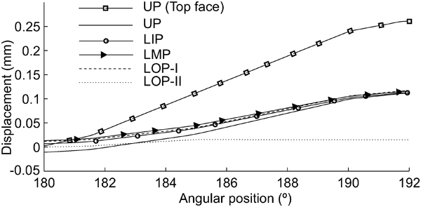
Displacement of working ends of lower punches, as well as displacement of top face of UP as function of angular position φ (pressure release stage)
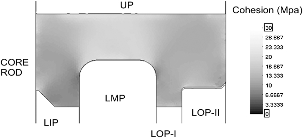
Contour plot of cohesion at end of pressure release stage
Withdrawal of die
Using as starting point the results obtained at the end of the pressure release stage, we tackle now the analysis of the die withdrawal phase. Three different ejection procedures are numerically tested. In these three alternatives, the compact is held between the UP and the two lower punches forming the lowest faces of the compact (LIP and LOP-I), which act, thus, as supporting punches as the die is withdrawn.
Option a: Hold stationary LMP and core rod
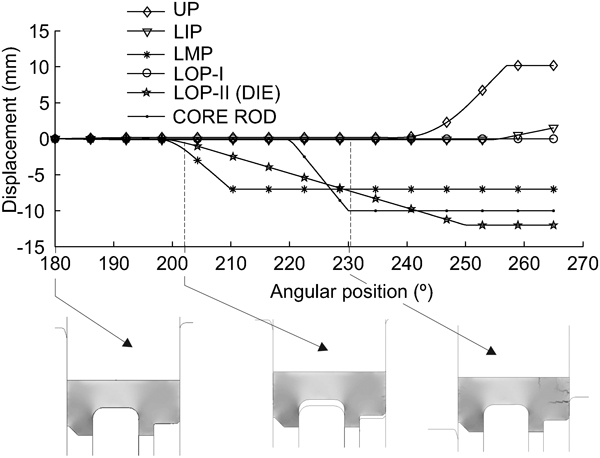
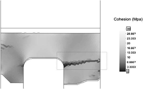
We will explore first the consequences of keeping fixed the lower middle punch and the core rod as the die is lowered. The tooling motion profile corresponding to this situation is depicted in Fig. 10. This diagram is accompanied by a sequence of three contour plots of cohesion computed at different times during the process. In the rightmost plot, which is shown also, in magnified form, in Fig. 11a, a horizontal decohesion path stemming from the outer wall is observed. This decohesion pattern certainly exhibits a distinctly crack-like appearance. However, the factor or factors that provoke its development are not readily apparent. In order to identify these factors and eventually clarify the mechanical origin, if any, of this localised loss of cohesion, we will propose two alternative, physically plausible hypotheses.
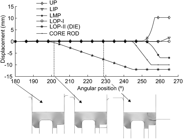
Prescribed punch displacements as function of angular position, together with sequence of contour plots of computed cohesion: case in which LMP and core rod are held stationary
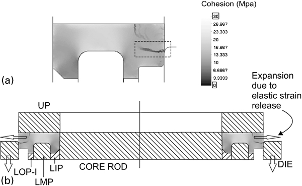
a contour plot of computed cohesion at φ = 203° for case in which LMP and core rod are held stationary and b schematic representation of effect of elastic strain release
The first hypothesis considers that the computed crack is due to the effects of elastic strain release in the radial direction. The observed mechanical degradation arises when the top face of the die is approximately flush with the top face of the lower middle punch, that is, when the main body of the part is clear of the die. The radial expansion of the main body coupled with the radial force exerted on the portion of the outer surface still restrained by the die tends to shear the compact along the radial direction, as pictorially depicted in Fig. 11b. Accordingly, this presumably shear mode (or mode II) crack can be eliminated by reducing the level of radial stress when withdrawing the die. One possibility to carry out this reduction is, as recommended by Zenger and Cai,14 to decrease the degree of confinement of the part by withdrawing the lower middle punch and the core rod. Another possibility to reduce the effects of radial expansion would be to diminish the hold down pressure exerted by the UP. However, this practice may conflict with the requirements for avoiding the crack promoting effect of uncontrolled punch deflections.
The other hypothesis advocates that the root cause of the numerically predicted crack is the ‘stepped’ character of the die. As already mentioned, the lower outer punch LOP-II is mounted on the die platen. Thus, as the die descends to the free the part, the LOP-II inevitably moves down away from the compact. This separation leaves the external portion of the compact vertically unsupported, and consequently, frictional downward forces between the die and the compact may tend to pull apart the main body and the bottom section. According to this hypothesis, thus, the horizontal crack develops predominantly under opening or mode I loading conditions. In turn, the bending deformation caused by these frictional forces would also explain consistently the formation of the other discernable decohesion path (Fig. 11a), which is located at the top face of the part.
In order to ascertain which hypothesis is more consistent, we will carry out two additional finite element analysis of the die withdrawal stage. In the first one (option b), the lower middle punch and the core rod accompany the die in its downward motion so as to release some elastic radial strain. In the second one (option c), the lower inner punch is kept fixed so that it can support the part while the die descends.
Option b: Withdrawing core rod and LMP simultaneously
The tooling displacement diagram, together with a sequence of three contour plots of cohesion, corresponding to this case is shown in Fig. 12. For ease of visualisation, an enlarged view of the contour plot at φ = 230° is displayed in Fig. 13a. Details of crack propagation through the mesh employed in the calculations can be appreciated in Fig. 13b. A qualitative comparison of the contour plot in Fig. 13a with the one contained in Fig. 11 immediately leads to the conclusion that withdrawing the lower middle punch and the core rod has not proved effective in eliminating the observed cracks. Both contour plots exhibit the same decohesion patterns, being the only discernable effect a slight decrease in the intensity of the degradation along these paths.
Prescribed punch displacements as function of angular position φ, together with sequence of contour plots of computed cohesion: case in which LMP and core rod are withdrawn simultaneously with die
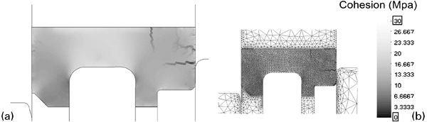
a contour plot of computed cohesion at φ = 230° (case in which LMP and core rod are withdrawn simultaneously with die for kinematics shown in Fig. 10) and b same contour plot showing mesh used in computations
Option c: Holding stationary LOP-II
The modelling of this scenario requires the consideration of a tooling arrangement different from the one described in the section on ‘Description of compacting press’. Rather than attached to the die platen, the LOP-II is assumed to be mounted on an independent platen so that it can support the compact during the downward motion of the die platen. Consequently, in this ejection schedule, the part is fully supported by four lower punches, as indicated in the diagram of tooling displacements shown in Fig. 14. Below this diagram, we show the cohesion distribution at three different times during the die withdrawal. The central plot depicts a situation in which the top face of the die is practically flush with the working end of the LMP, which is the relative position of the die and the LMP at which the decohesion patterns reported in the preceding simulations were detected. In this case, by contrast, the cohesion distribution exhibits a relatively uniform aspect, and no evidence of intense loss of cohesion is observed. This fact clearly substantiates the second hypothesis advanced previously. Thus, we can conclude from the numerical simulations carried out that the root cause of the numerically predicted cracks (Fig. 11a) seems to lie in the ‘stepped’ character of the die.
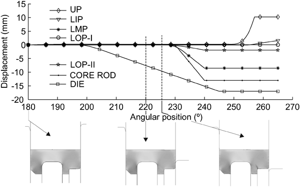
Prescribed punch displacements as function of angular position together with sequence of contour plots of computed cohesion: case in which LOP-II moves independently from die
Incidentally, examination of the rightmost contour plot in Fig. 14 (displayed in magnified form in Fig. 15a) shows a vertical, slightly leaned inwards, decohesion path that develops at the junction of the levels formed by LOP-I and LOP-II. Although the primary goal in studying this ejection schedule was to merely confront the hypotheses advanced at the onset of the discussion rather than rigorously investigate the defects formed in producing the part using this tooling arrangement, it may prove instructive to, at least superficially, inquire about the root cause of this decohesion pattern.
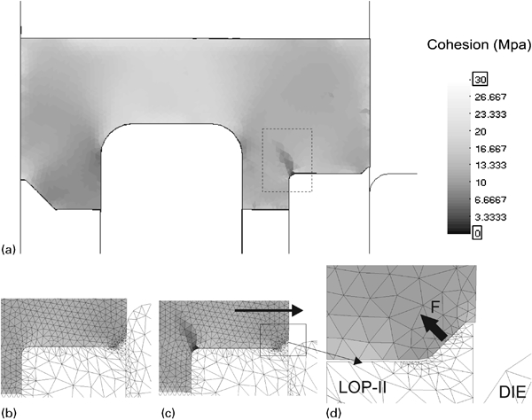
a contour plot of computed cohesion at φ = 226° (case in which LOP-II moves independently from die), b, c enlarged views of zone at which crack is formed and d schematic representation of force generated on protruding rim due to radial expansion
A plausible explanation for this localised loss of cohesion may lie in the particular geometry of the LOP-II. Inspection of the plots in Figure 15b and c indicates that loss of cohesion in the corner region occurs right after the compact is totally freed from the radial restraint imposed by the die. The top surface of the LOP-II is not completely horizontal, but it has a vertical protruding feature (0·2 mm height, see Fig. 1) at the outer edge. As the compact emerges from the die, it tends to expand radially due to elastic strain release. The radial expansion of the lower portion of the part, however, is hindered to some extent by the protruding feature. This restriction generates a lifting force (Fig. 15d) that, considering that the leg section is restrained by the radial action of the LOP-II and the LMP, induces bending of the part. The computed decohesion path might be ascribed thus to the effects of such bending deformation.
Ejection of modified part
The main implication of the geometry modification introduced in the revised design (the abruptness of the cross-sectional change between the outermost levels is eliminated by a tapered surface, see Fig. 2) is that it dispenses with the need for two separate lower outer punches. Accordingly, the two thin walled lower outer punches LOP-I and LOP-II employed in shaping the part in its original conception are replaced by a single, more massive, lower outer punch, abbreviated LOP, with a tapered top surface. Note that this modification is somehow consistent with the hypothesis put forward in the previous section for explaining the difficulties in producing a free defect part using the ‘stepped die’ tooling configuration.
We bypass the details of the pressing kinematics and started conditions employed to press the part in its revised form, and in what follows, we concentrate exclusively on presenting the computed results corresponding to the ejection stage; the reader is referred again to Hernández et al. 13 for further information on pressing conditions with the revised geometry.
The tooling motions corresponding to the ejection of the modified part, which are incidentally the motions with which the part was finally manufactured, are displayed in Fig. 16. In the pressure release stage, the lower outer punch and the lower middle punch are programmed to move upwards 0·08 and 0·06 mm respectively, while maintaining a hold down force of 10 tons. Then, the die is progressively lowered so as to free the part. The downward motion of the die is followed by the withdrawal of the core rod and the lower middle punch. Finally, the UP moves up away from the compact, and the lower inner punch is slightly lifted so as to ready the part for being removed by the gripper. The cohesion distribution computed at four different positions is shown also in Fig. 16. It is apparent that the cohesion field remains unaffected during the ejection process. The model predictions, therefore, are in accordance with the experimental evidence and confirm the benefits of manufacturing the part according to the revised design.
Prescribed punch displacements as function of angular position together with sequence of contour plots of computed cohesion (modified part)
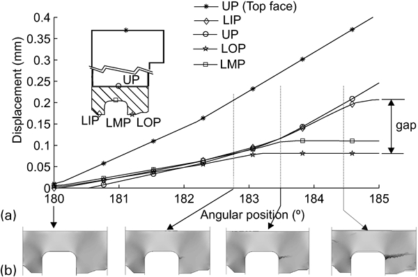
Pressure release stage with total axial unloading
Finally, by way of evaluation of the ability of the model in reproducing other typologies of ejection cracks, we will numerically examine how the structural integrity of the part would have been affected by a sudden release of the axial force exerted by the UP, i.e. a case in which the UP moves up away from the compact while the lower platens remain fixed (no hold down force). In Fig. 17, the graphs of the computed displacement of the punch working ends versus the angular position are displayed. Below this diagram, we show a sequence of contour plots of computed cohesion. Examination of these contour plots clearly reveals a horizontal decohesion path emanating from the junction corner and propagating outwards through the section change. At the end of the pressure release stage (Fig. 18), the computed decohesion path spans the whole section, a fact that suggests that fracture may be imminent.
Total axial unloading case (modified part)
Contour plot of cohesion at end of pressure release stage: total axial unloading case (modified part)
The origin of this localised loss of cohesion can be readily explained from the punch displacement diagram displayed in Fig. 17. Since the lower inner punch LIP is larger and has a smaller cross-sectional area than the other lower punches, it experiences a larger elastic deflection, and consequently, it pushes the compact upward, generating gaps between the working ends of the LMP and LOP. In this process, the outer flange is partially gripped between the LMP outer wall and the LOP inner wall, due to friction effects. The combination of this restraining action and the upward movement of the LIP places in tension the corner region, and the crack is therefore induced.
Conclusions
The primary goal of this work was to explore and evaluate the possibilities and limitations of using a finite element model proposed by the authors elsewhere 8 8,9 as a tool for assisting in the solution of problems linked with cracks generated during the ejection phase in PM die compaction processes. For this purpose, a carefully detailed case study of the compaction of an axially symmetric, multilevel adapter in an advanced CNC press machine has been performed. Mathematical and numerical formalities have been left aside, and attention has been confined exclusively on how information generated from simulations can be ‘harnessed’ to solve a practical problem. Specifically, the aim was to ascertain the root cause of the seemingly inexplicable difficulties encountered by the manufactured in fabricating the concerned part according to the initial customer's specifications. Scrutiny and comparison of the computed cohesion distributions resulting from alternative ejection routes have allowed us to advance a plausible reason for these difficulties: it seems that the root cause lies in the ‘stepped’ character of the die. The outermost lower punch is mounted on the die table, and thereby, as the die descends, the lower outer punch LOP-II leaves inevitably unsupported the outer portion of the flange; frictional downward forces between the die and the compact tend thus to pull apart the main body and the bottom section.
The detection of the protruding feature in the outer punch as a potential source of problems illustrates how numerical simulations could be of great assistance also in a prospective examination of the viability of a given tooling arrangement. In this case, model predictions would have suggested that a four-lower platen configuration is also apt to lead to defective parts. Needless to say, whether to use one configuration or other must remain an engineering decision: the role of numerical simulations in the decision making process should be to guide engineering judgment, not to supplant it.
Indeed, we must interject here a word of caution in connection with the limitations of the model: even if every precaution to ensure correctness and eliminate numerical errors is taken, the model keeps being but a simplified picture of physical reality. It is important, thus, to guard against unrealistically high expectations and know which questions can be answered and which cannot. For instance, in a prospective study, the numerical simulation of a given ejection route attempts, in principle, to answer the question: will this ejection route or tooling configuration lead to a free defect part? Such a question, however, demands a categorical yes or no answer: there is no flexibility, and the risk of arriving at wrong conclusions is thus high. Except in some pathological cases, such as the uncontrolled punch deflections (Fig. 18), one should refrain from drawing definite conclusions from a single simulation. As shown in this work, a more fruitful strategy consists of running several analyses for different alternative ejection procedures and limiting oneself to answer the question: which of these ejection procedures or/and tooling configurations represent more favourable conditions for ejecting the part safely from the die? Although the answer to this question remains surely uncertain, judicious interpretation and simple qualitative comparisons of cohesion contours may give a hint of which ejection option has the highest probability of success.
To handle the inescapable uncertainty associated with modelling errors in a more systematic and rigorous manner, one should abandon the confines of deterministic simulation and move to more sophisticated, statistical based methods. The work by Rolland et al. 10, succinctly outlined in the preamble, provides an excellent guideline for accomplishing this task in the context of PM compaction modelling.
Footnotes
Acknowledgements
The Spanish Ministry of Science and Innovation and the Catalan Government Research Department are gratefully acknowledged for financial support under grant nos. BIA2008-00411 and 2009 SGR 1510 respectively. The authors wish to thank AMES S.A. for supporting the experimental part of this research; a special debt of gratitude is owed to E. Sánchez and J. L. Celeiro for their endless patience in helping the authors understand the intricacies of CNC press machines.
†
In practice, this tooling arrangement with an independently movable LOP-II was not tested due to equipment limitations.