
Abstract
Gas atomisation phenomenology of liquid metals and alloys is both intriguing and instructive. Predating atomistic studies of melt disintegration by almost three decades, it provides a functional means of correlation between drop sizes and processing parameters, as is the case in liquid metal spray forming. In this article a concise but thorough compilation of melt disintegration phenomenology is provided, with emphasis on high pressure gas atomisation, inclusive of notation on mean particle diameters, the role of viscosity, density and other dimensionless ratios that enter as variables in high pressure gas atomization and spray forming, as well as break up of a liquid column and theories of drop disintegration in flight. The article concludes by introducing the very efficient Surface Wave Formation principle which facilitates the treatment of complex atomisation geometries and turbulent regimes.
Introduction
An effective way of developing alloys is via rapid solidification (RS), offering refinement of microstructures, formation of new phases and solubility extension. To achieve RS conditions, high solidification front velocities must be maintained. This is possible at high melt undercoolings and/or high heat extraction rates, typically achieved if at least one dimension of the melt is small enough and the melt is brought in contact with an efficient heat sink such as a solid metal substrate or a convective fluid. Depending on the manner in which heat is extracted from the material, cooling rates higher than 103 K s−1 can be achieved. Among popular RS techniques are chill casting, melt spinning, splat quenching and in situ melting, as well as the very versatile gas atomisation which constitutes the melt disintegration stage in spray forming (SF) (also termed spray casting and spray deposition). SF allows high production rates as well as a variety of fabrication shapes such as disks, billets and sheets, cutting down on cost compared to the more elaborate multistep PM routes. This technique has been successfully applied in the manufacturing of Al alloys, high speed steels, superalloys and metal matrix composites while Leatham, Ogilvy and Elias 1 have reported that in the form of the Osprey Process it can minimise the adverse effects of oxides on the surfaces of powders of reactive materials such as magnesium, titanium and aluminium alloys.
In SF, atomisation of a liquid metal stream takes place when the melt is acted upon by a number of high velocity gas jets causing its disintegration into drops leading to the formation of a conical two-phase spray jet. 2 If the drops are of considerable size they may break into smaller fragments during flight. The resultant spray jet is then intercepted by a metal substrate in such a way that the impinging drops consolidate to form a spray deposit or preform. The shape of the preform, its microstructural characteristics and its properties depend on the state of the metal drops before their arrival on the substrate. 3 The gas, acts as a heat sink cooling the drops mainly by convection, hence, the rate of heat extraction from a drop increases with increasing gas velocity and decreasing drop diameter. Depending on their diameter, different sizes can be fully solid, semisolid or fully liquid at the time of impact. High pressure gas atomisation (HPGA) conditions are achieved when the injection pressure of the atomizing gas is considerably high and, as a result, the gas velocities reach sonic or supersonic values. There are two major obstacles in dealing with the theoretical aspects of such a process:
the highly turbulent nature of the gas phase under the high pressures used. Typically the gas is injected at 300–800 psi (2·1–5·5 MPa) out of nozzles not larger than a few millimetres in diameter
the seemingly chaotic mode of disintegration of the initial melt delivery into drops as well as the secondary break up of the drops themselves.
The theory of particle motion under the combined effect of external forces, the heat extraction from the melt by the gas phase as well as the turbulence and compressibility of the gas are well established disciplines and have already been applied to HPGA. In earlier modelling attempts, such as those of Mathur 4 and Uhlewinkel and Bauckhage, 5 the drop distribution produced in the early stages of atomization enters either as an approximate size distribution or as an average size characteristic of the spray; typically, the latter is estimated via the Lubanska 6 equation, the most popular among a plethora of empirical correlations. Recently, atomization modelling has focused on stochastic simulation of the liquid jet and primary atomization in terms of Reynolds averaged Navier-Stokes mixing 7 and on turbulent atomization conditions.8–12
The phenomenology of the atomization process, however, is both instructive and intriguing. It has produced a wealth of functional models,13–21 that address atomisation parameters such as the nature of the gas and melt phase, gas injection pressures and melt superheat. A critical assessment of the analytical approaches on deformation and splitting of a liquid globule under the effect of a gas flow field tends to group these modelling approaches into three main categories:
mathematical relations expressing a balance of forces thought to be of critical importance in the break up phenomena, e.g. the Weber ratio (number) 22
mechanistic models attempting to account for the deformation histories of the liquid bodies under consideration 23
studies based on the theory of wave growth on the surfaces of liquid sheets or columns, induced by gas flow.24–26
In the past, the author has found SF phenomenology highly functional towards correlation between drop sizes and processing parameters. For example, the surface wave formation (SWF) theory and corresponding model is an effective numerical such scheme for the treatment of atomization rigs with a fractional computational footprint.27,28 Here, a concise compilation of the most usable phenomenology on melt disintegration is provided, with emphasis on HPGA of liquid metals and alloys. The rest of the article is structured as follows: notation on mean particle diameters is discussed in the section on ‘Mean particle diameters’ and the role of viscosity, density and other dimensionless parameters that enter as variables in HPGA are presented in the section on ‘Viscosity, density and dimensionless parameters’. An introduction is, then, given of gas atomisation in the section on ‘Viscosity, density and dimensionless parameters’, atomiser designs in the section on ‘Gas atomisation’ and spray forming in the section on ‘Atomiser designs’. The more fundamental aspects of atomization are discussed in the section on ‘Fundamental aspects of atomisation’; at first the break up of a liquid column is introduced in the section on ‘Break up of liquid column’, followed by theories of drop disintegration in flight in the section on ‘Drop disintegration’. In conclusion, the very effective SWF theory is presented in the section on ‘Surface wave formation’.
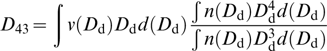
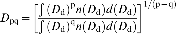
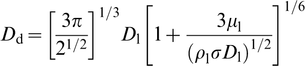
Mean particle diameters
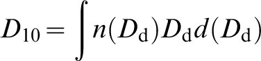
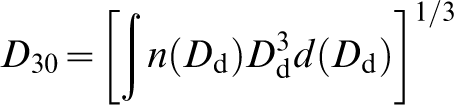
The concept of the mean diameter is of fundamental importance in the characterisation of sprays. A popular size in atomisation and spray forming applications is the D50 mass median diameter. It is the diameter below which lies 50% of the total mass of the particles in the spray.
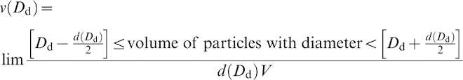
Upon measuring the diameter of a particle, be it solid or liquid, two errors are normally involved, that of particle shape and that of the measuring technique. Accordingly, different measurement techniques provide varying number, surface, volume or mass information and unless the particle shape is known the different mean diameters cannot be interrelated. If N drops of various sizes pass through an infinitesimal area per unit time, then the probability density function n(Dd) follows the expression given by Yule and Dunkley
29
as
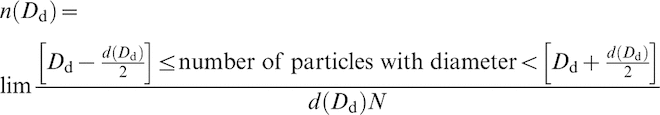
D10 is the numerical mean diameter
D30 is the volume mean diameter
D43 is the diameter derived from the volume size distribution
D20 is the linear arithmetic mean diameter used in the study of absorption phenomena
D21 is the surface area median diameter also used in absorption studies
D31 is the volume mean diameter used in the description of evaporation phenomena
D32 is the Sauter mean diameter. In effect, it is the diameter of a particle having a volume to area ratio equal to the ratio of the total volume to the total area of the particles in the spray. It is used in expressing atomisation efficiency as well as in mass transfer and combustion applications.
Viscosity, density and dimensionless parameters
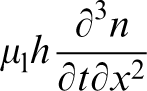
The quantities affecting break up are the surface tension, viscosity and density of the melt, generally resisting break up, and the dynamic force of the gas phase that drives the disintegration. Many melts, particularly superheated metals and their alloys can be considered to be Newtonian fluids so that there is no variation of viscosity with shear rate. The liquid dynamic viscosity μl is the ratio of the viscous shear stress in the melt, to the velocity gradient across the melt. The viscosity of liquid metals is, nevertheless, temperature dependent and increases significantly at low superheat temperatures. Inside the drop itself, there can be gradients of the viscosity coefficient, depending on the local drop temperature, which can in effect lead to variable atomization quality. The great majority of attempts to model atomization of liquid metals consider the liquid viscosity as a constant, temperature independent quantity. 30 In contrast to the effects of liquid surface tension, the relationship for the energy required to overcome the liquid viscous forces during break up is not straightforward. This is because this energy depends on the distribution of viscous shear stress inside the melt and on the variance of this distribution with time.
In addition to liquid viscosity, the density of the liquid phase can have a significant impact on the atomization mechanism. 27 Unlike surface tension, a high metal density does not necessarily act against fragmentation. The parameter affected most by liquid density is the atomization time, since it takes longer for a net force to accelerate and detach part of a liquid body if the density is higher. 29
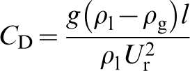
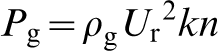
In two phase flow problems and especially in the case of the deformation of fluid particles under the influence of a gas flow, as is the case in HPGA and SF, it is common practice to compare the magnitudes of the forces involved in a phenomenon at any instant. Of particular merit in such cases, the drag coefficient CD defined as the ratio between the gravitational force and the inertial force of a particle, is used to include the effect of flow separation in the expression of the gas pressure acting on the free liquid surface. In the particular case of the motion of the gas relative to the melt being vertical (as is the case in atomization and spray forming) CD is expressed as
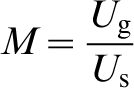
Forming ratios of forces yields a number of dimensionless ratios or groups that can serve as valuable criteria for the onset or the relaxation of a process like break up of a drop. The most important of these ratios are the following:
the Mach number M defined as the ratio between the velocity of the gas Ug and the velocity of sound Us propagating through the gas
the Reynolds number NRe, which is the ratio of the inertial to the viscous forces of the gas
the Weber number NWe defined as the ratio between the inertial force of the gas phase and the surface tension force of the particle
Gas atomisation
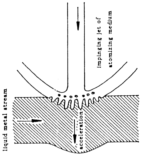
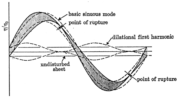
In atomisation, a liquid layer which can have the form of a cylinder, a column as shown in Fig. 1, or a sheet, is acted upon by gas and is broken up into droplets. As can be seen in Fig. 1, the surface of the melt is at first disturbed by a perturbance resembling a sinusoidal oscillation and is then broken up into unstable liquid bodies, the ligaments, which in turn break down into droplets. The droplets may undergo further disintegration and are cooled mainly through convection as they travel downstream following the motion of the gas. Cooling of the droplets by radiation also takes place but radiative heat losses are insignificant compared to convection. High pressure gas atomisation (HPGA) allows the bulk production of powders under RS conditions. The cooling rates achieved are in the range 103 to 105 K s−1 and depend on powder size and type of atomising gas.
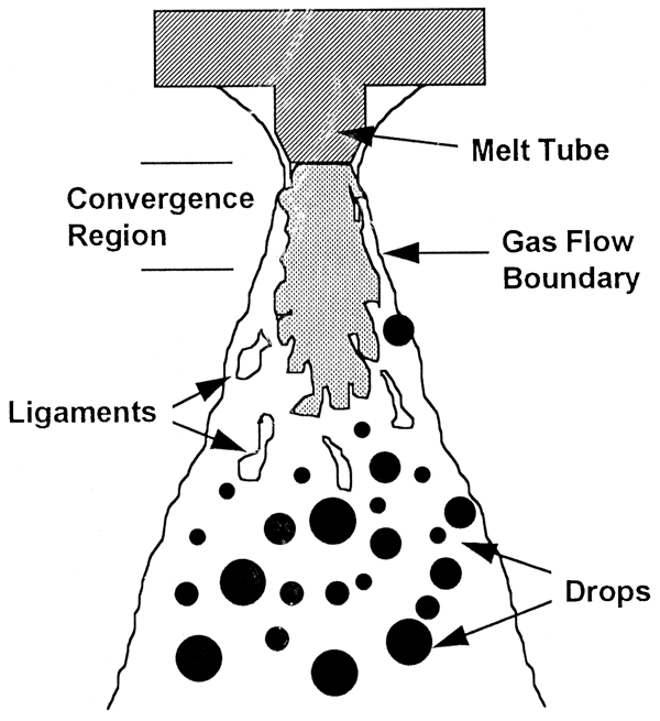
Principle of atomisation 2
The range of metals that can be gas atomised is extremely wide and extends to all metals that are capable of being melted industrially. Exceptions are refractory metals (W, Mo, etc.) and very reactive metals such as Ti. In the latter case, special gas atomising assemblies are currently being developed, based on skull melting methods to avoid freezing of the melt stream. The main factors affecting the atomisation of a particular metal are the volume of powder needed, the melting point of the metal, the reactivity of the metal and the desired properties of the produced powders. The various techniques available for the atomization of metals have been summarized by Yule and Dunkley. 29 In general, the lower the melting point of a metal, the wider is the variety of techniques available for its atomisation. The particle size distributions of the different atomisation techniques vary widely. Methods of powder size analysis and problems related to accuracy, reproducibility and comparison among different methods will be briefly discussed below. The shape of the particle size distribution is greatly dependent on the design of the atomiser, but most of the external mixing, twin fluid atomisers give rise to similar distributions. The physical properties of the gas and melt phases are also crucial to the characteristics of the powders produced. For example, gas atomisation of copper in an external mixing, twin fluid atomiser always produces powders with a mass median size 50% lower than steel powders produced with the same technique. As a general rule, tin, lead and zinc can yield sub-10 μm median sizes; aluminium is restricted to ∼20 μm, while the limit for nickel, cobalt and iron is roughly 30 μm. The particle shape is also very dependent on the specific atomisation technique used as well as the properties of the media involved. For example, spherical powder particles are produced by inert gas atomisation of Al alloy melts as compared to the irregularly shaped of air atomised ones. The time required for the break up events to be concluded controls the cooling and solidification of drops through the gas–melt interaction and depending on their temperature drops can lose their sphericity in flight or coalesce with other particles.
A good understanding of the gas atomisation process requires an evaluation of the processing parameters involved. Bruce See and Johnston 14 studied a free fall atomisation system of four Nitrogen jets impinging on streams of liquid tin or led. They reported that increasing gas flow rates produced finer powder sizes for both metals. Ünal 20 used an up-draught atomisation assembly bearing a close coupled atomizing die to study the disintegration of Al alloys by nitrogen, helium and argon gases. Helium produced the finest powders under any set of conditions, while Argon yielded the coarser ones and Nitrogen gave particles in an intermediate range. An increase in the metal flowrate caused the formation of coarser particles in the spray. Ingebo 16 investigated two phase flows of water atomised by Nitrogen in a twin fluid atomiser. It was reported that the D32 size, determined by means of a laser scattered light scanner, increased with increasing water flowrate. The radial distribution of drop sizes was also determined to be one of decreasing diameters with increasing distance from the central axis of the spray, with the finest particles on the outer edges of the flow being smaller compared to the central ones, by a factor of three. This trend is opposite to experimental evidence from typical close coupled atomizers. Liu et al. 31 studied the atomisation Al by Helium at supersonic gas speeds (Mach number, M, equal to 1·7) in a close coupled atomizing die configuration. The particle velocity and heat transfer coefficient profiles for a range of particle diameters were calculated as a function of flight distance. For a gas speed of 1700 m s−1 a 15 μm drop was calculated to reach a velocity of 1200 m s−1 that would rapidly decrease downstream, while a 150 μm particle would reach 600 m s−1, exhibiting a slow decay further downstream. The heat transfer coefficient ranged between 104 and 105 W K m−2. Snyder, Senser and Lefebvre 32 made a series of case studies on the effect of the physical properties of melts atomised by injection into a stagnant atmosphere, by fan spray atomizers producing gradually disintegrating sheets. It was reported that the D32 particle size increased with increasing melt viscosity, increasing melt surface tension and reducing melt injection pressure. An empirical correlation was also proposed, closely fitting the experimental data.
Atomiser designs
Atomisation is dependent on the energy transfer from a high velocity gas medium to a relatively low velocity liquid stream and the design of the particular atomizer will determine the size distribution produced. It should be noted that the word atomiser is used here to describe the geometry of the gas jets causing the disintegration in respect to the liquid melt stream, rather than the geometry of the whole atomisation chamber.
The most important criterion of the performance of an atomiser is the distribution of drop sizes produced. Small drop sizes are important in most atomization cases when fine alloy powders are required or when a high specific area is needed, as in the case of combustion applications. In general ‘twin fluid atomization’ is the term embracing all techniques utilising pressure energy supplied from one fluid to cause the disintegration of another. For the atomisation of such liquids as oil or aqueous solutions, the continuous phase, i.e. the medium causing the disintegration, is normally a gas or steam. In the case of the atomisation of molten metals, it is common to use gas, water or oil as the continuous medium. The twin fluid atomisers can be distinguished into those who perform internal mixing and those who allow external mixing. The internal mixing ones (Fig. 2) make effective use of the kinetic energy of the gas phase to produce fine sprays, as opposed to the external mixing ones, shown in Fig. 3. In the atomisation of molten metals external mixing designs are exclusively used since a non-pressurised flow of melt can be used and orifice blockage problems are less likely.
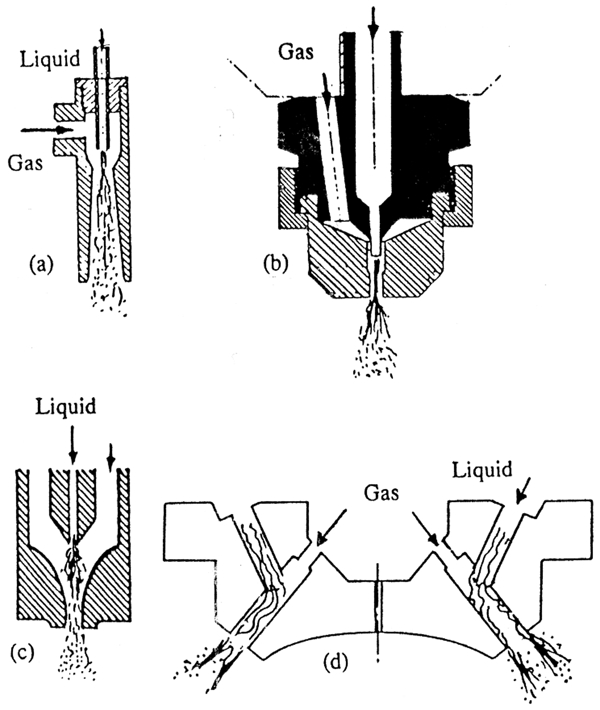
Types of internal mixing atomisers 42
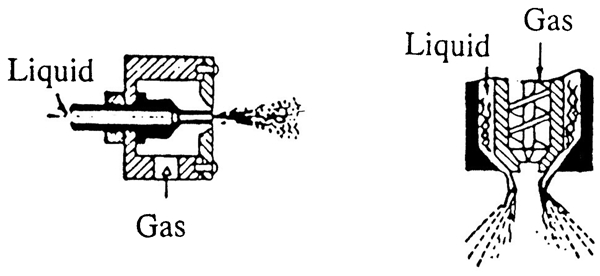
Types of external mixing atomisers 42
There are two large categories of twin fluid, external mixing atomiser configurations, of particular importance in the area of molten metals. The first wide category is based on the free fall atomiser, in which the gas flow travels a considerable, in terms of loss of momentum, distance before interacting with the melt, as shown in Fig. 4a. As a result, the disintegration of the dispersed phase is not as complete as in the case of the close coupled designs and the cooling of the melt is limited. Excessive cooling and thermal shock of the melt delivery tube is avoided.
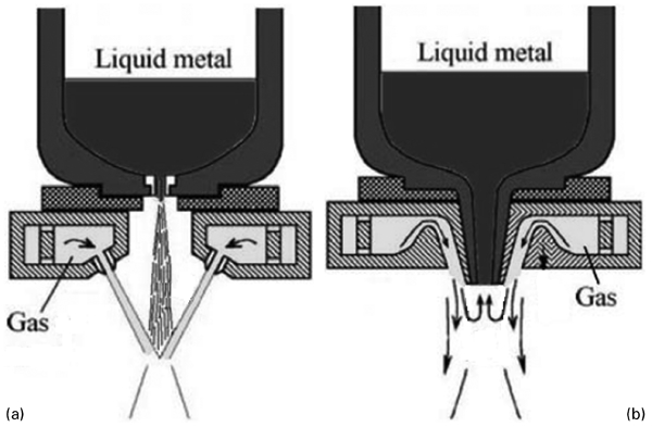
a free fall atomiser and b close coupled atomiser design 43
The second type, the close or confined or close coupled atomiser designs allow the melt to be delivered through a high temperature ceramic tube, e.g. boron nitride, and to be acted upon by a number of gas jets at the point of exit. The gas phase exits from an annulus or a number of discrete jets in a ring configuration. This type of atomiser is shown in Fig. 4b. The distance between the point of interaction between the gas and the melt and the tip of the melt tube is kept sufficiently short, although a back flow opposite to the direction of feed motion of the melt can be created if this distance becomes too small. The most basic advantage of this type of atomizer is the better use of the kinetic energy of the gas before the individual gas flows mix, diverge and lose momentum. Nevertheless, a distinct drawback is the occasional freezing of the melt delivery tube due to the pronounced cooling effect of the high gas velocities, which may cause the blockage of the tube.
Spray forming
Spray forming (also termed spray casting, spray deposition or liquid dynamic compaction) can provide a cost effective means of near-to-net shape manufacture compared to conventional methods. It allows the production of bulk preforms of relatively high density by one operation directly from molten metals, offering an advantage compared to the multi stage RS/PM route of gas atomisation, powder collection and screening, canning and degassing and consolidation, as shown in Fig. 5. Taking advantages of rapid solidification phenomena, at least in the early stages of atomization, SF offers materials with improved mechanical properties, decreased segregation and refinement of grain size compared to conventional ingot metallurgy techniques. Being an energy consuming method, SF best delivers results when applied on a large scale production line. A description of the most important spray forming methods has been given by Singer. 33 In comparison to the RS/PM route, SF allows the elimination of high cost process steps like powder sieving after atomization, powder canning, degassing and hot isostatic pressing.
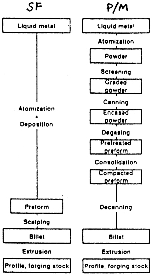
Comparison between spray forming (SF) and powder metallurgy (P/M) production routes 42
In spray forming the principle of gas atomisation is utilised, where a melt is disintegrated into droplets through an interaction with a gas phase, frequently of high velocity and density. The droplets are transported and cooled down by the gas until they impinge on a metallic substrate positioned at a certain level below the atomizing assembly. The size distribution of drops across the spray depends mainly on the atomiser design. Depending on the flow conditions, different drop sizes arriving on the substrate will have experienced different thermal histories. In the case of a fully solid particle, impact on the substrate will not normally alter its shape and as a result the trace of such a particle will be circular in a cross section of the deposit. The largest drops have an increased possibility of arriving on the substrate fully liquid. These drops on impact form splats, i.e. they are splat quenched by the cooler substrate. The intermediate sizes, being partially liquid, are deformed to an extent and solidify relatively fast. Under typical SF conditions, drops up to 40–50 μm are normally fully solid, while sizes between 50 and 150 μm are semisolid. Particles exceeding 150 μm in diameter are most likely to be fully liquid and therefore can not be detected metalographically in the end product. The melt supplied by the arrival of the largest drops will tend to fill the voids created between the solid particles, thus reducing the porosity of the end product. Liu et al. 31 presented a numerical model on the deformation of molten metal drops on interaction with a substrate during spray forming. The effect of process variables in SF has been studied by Kim and Jones. 17 SF was carried out in a close coupled system for a series of Al alloys atomised by Nitrogen. High speed cinematography (500 frames s−1) was used to evaluate droplet velocity. Such a framing speed could prove to be inadequate for fast moving drops, as is the case in HPGA. The velocity of the gas Ug was found to agree with the empirical formula Ug = a–bx where x is the axial distance from the die and a, b are constants. With increasing pressure, the pre solidified drops hitting the substrate increased in number.
The behaviour of the gas phase during close coupled atomisation was studied by Liu et al.;
31
in their study, a close coupled atomiser was used and Mach numbers up to 1·7 were achieved with helium as the atomizing medium. A Pitot tube with an outer head diameter of 5 mm was used to measure the gas velocities. Compressibility effects were taken into account through the use of the relevant equations for compressible flow
Fundamental aspects of atomisation
Gas jets impinging on a melt column causing its disintegration are a common feature in close coupled atomisers. Such a configuration results in the formation of a twin fluid spray jet downstream of the point of initial interaction between the gas and the melt, to be referred to as the point of initial atomisation. The break up phenomena especially in HPGA, constitute a seemingly chaotic process and only few attempts have been made towards their mathematical description. According to the SWF theory, the disintegration of a liquid column acted upon by a gas phase is due to the formation and subsequent amplitude growth of sinusoidal waves on its surface. A large amount of published work has dealt with the disintegration of a liquid stream injected into a stagnant atmosphere, which is a similar problem.
Break up of liquid column
A spray jet can be formed either by injection of a fluid into a stagnant gaseous medium or by the injection of both a liquid and a gas phase from a spray nozzle, such as a close coupled atomiser. Upon formation of the spray jet, two flow regions can be distinguished, as shown in Fig. 6. The first region, extending from the tip of the injection nozzle to a limited distance downstream, consists of a core of fluid with a finite length which is presumed to be made up by dense spray. Further downstream of the core a conical flow region is formed by the divergence of the spray jet, where individual drops are clearly visible. Depending on the flow conditions, the properties of each region change accordingly. Most published research is concerned with the macroscopic behaviour of spray jets and concludes that with increasing liquid injection velocities four discrete flow states can be distinguished:
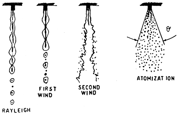
Characteristic regimes of spray jet 44
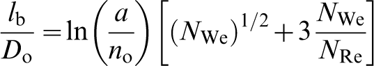
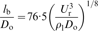
at low liquid injection velocities, the spray is inside the Rayleigh regime, where axisymmetric wave instabilities grow on the liquid surface, causing the detachment of drops, the diameter of which is larger than the jet diameter and the Weber numbers have low values (NWe≈5). This regime was also detected by Hiroyasu et al.
15
and was termed the laminar region. The jet surface area is unstable for all wave numbers with kRo<1, where k is the wave number of the disturbance (defined as k = 2π/λ where λ is the wavelength of the surface wave) and Ro is the initial radius of the (unperturbed) jet. The maximum growth rate (i.e. the rate at which the amplitude increases) of the disturbance occurs at a wavelength equal to a multiple of the jet radius. Reitz
19
reported λ = 9·02Ro. Zanelli
21
suggested that motion of the disturbed liquid surface in this regime was sinusoidal and the disturbance grew exponentially with time. The break up length lb of the jet, i.e. the length at which the dense core of the jet was no longer distinguishable and the spray diverged, was suggested to be
a further increase in the Weber number, i.e. the relative velocity, NWe≈18 as reported by Reitz,
19
introduces the inertial effect and the density of the gas as significant factors in the growth of the surface wave instability and brings the spray jet into the first wind induced regime, or the transition region.
15
The wavelengths causing disintegration of the spray are shorter than in the Rayleigh regime. The drop sizes are still of the order of the jet diameter. In this regime the interaction between the liquid jet and the surrounding gas and the combination of surface tension and the ambient pressure force favours the growth of axisymmetric surface waves. Non axisymmetric as well as helical deformations are also present. The break up length of the jet for this regime, as proposed by Zanelli,
21
is
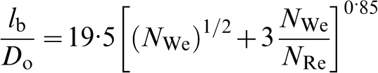
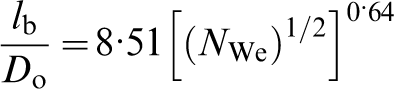
when the Weber number reaches larger values, e.g. NWe≈45, the inertial effect of the gas on the characteristics of surface wave growth become even stronger and the spray enters the second wind induced regime, or the turbulent region.
15
The maximum growth rate occurs at larger wave numbers; therefore the wavelengths favouring surface instability and break up are now even shorter. Drop sizes are much smaller than the jet diameter and, if NWe becomes sufficiently high, they grow to be altogether independent of the diameter of the jet. The distance between the point of drop detachment and the tip of the melt delivery tube decreases as the jet velocity increases. For turbulent jets the following equation was proposed to describe the break up length of the jet
21
a final atomisation regime or spray region 15 is reached at high Weber numbers, NWe≈226 as reported by Reitz. 19 Break up commences at the very nozzle exit and the spray has a conical geometry downstream. The disintegration mechanism at this stage is yet unknown mainly due to the dense spray surrounding the jet. In this regime the drop sizes are considerably smaller than the jet diameter. A study of the radial structure of the spray jet made by Zanelli 21 revealed a main jet region situated in close proximity of the spray axis, where the liquid drop density and velocity were large. Between the spray jet boundary and the main region a mixing flow region was detected, inside which the spray density was found to be smaller and turbulent dispersion of particles was quite pronounced. Hiroyasu, Shimizu and Arai 15 and Arai et al. 35 reported that an increase in the injection velocity caused the break up length of the jet to fluctuate until it reached an ultimate constant value irrespective of the injection velocity. It was also reported that with increasing ambient pressure the break up length of the jet generally decreased.
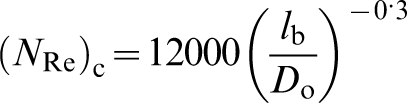
The parameters affecting disintegration of sprays were studied by Pai and Nijaguna 18 who also gave empirical expressions for them. The following parameters were identified
the disintegration wavelength λ. It was suggested that drop formation for wavelengths less than 1·2247 diameters of stream was impossible. This meant that disturbance wavelengths between 1·5 and 3 times the jet diameter could create the finest spray possible
the critical Reynolds number (NRe)c for which there is a transition from laminar to turbulent flow, was related to the break up length of the jets as
the critical Weber number N(We)c. The critical drop size Dc, which is the size that determines whether a drop will undergo further disintegration or not, corresponds to a critical Weber number
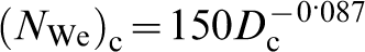
for turbulent flow conditions the critical Weber number was in the range 15–22
the density ratio ρg/ρl, which is the ratio between the densities of the gas and melt phase respectively. As the value of this ratio increases the rate of disintegration is increased and the resultant spray becomes finer
the ratio between the viscosities of the gas and melt phases. Variation of the viscosity of the gas phase did not have any appreciable effect on the atomisation process. Increase of the liquid viscosity retarded atomization at high relative velocities, reducing the specific surface that resulted from break up.
Drop disintegration
The empirical correlations and analytical relations accounting for the phenomena of jet disintegration as well as the size of drops produced in atomization have been reviewed by Mehrotta.
36
Hinze
22
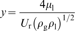
studied the splitting of drops during the final stages of the disintegration processes and suggested that there is a common mechanism describing the penetration of ligaments of one fluid into another. These ligaments break into drops of different sizes, which may produce secondary droplets. Indeed, the situation in which a drop is formed at an early stage of atomisation and then breaks up into smaller droplets due to the resistance in a high velocity environment, is termed secondary atomisation. It is generally an effect to be encouraged. The aerodynamic force acting on a drop of diameter Dd depends on the relative velocity between the gas and the melt phase Ur and the gas density ρg. Whenever a drop is deformed it is under the influence of internal forces such as viscosity and surface tension as well as the external pressure from the gas phase. These three forces control the deformation and break up of the globule. Hinze
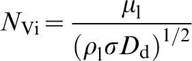
22
chose two dimensionless groups to describe the balance of forces acting on a drop during its disintegration: the Weber number and the viscosity number NVi, defined as the ratio between the viscous and the surface tension forces inside the drop
Hinze
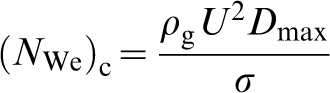
22
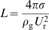
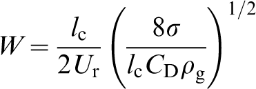
also proposed that in the case of turbulent motion of the continuous phase, as is the case in HPGA, (NWe)c is not the same for all the drops and a statistical mean value of (NWe)c would determine the average critical droplet size in the flow field. The flow patterns and types of deformation which produce the lowest value of (NWe)c will be of the greatest significance in determining this statistical mean value. The requirement for secondary break up to occur in a turbulent flow field due to viscous shearing forces of the gas is that the size of both the deformed and non-deformed drops be larger than that of the smallest gas turbulent scales. The dynamic pressure forces are caused by the changes in velocity over distances equal (at the most) to the diameter of the drop. In this case the critical Weber number is
A more analytical approach was proposed by Gordon
37
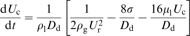
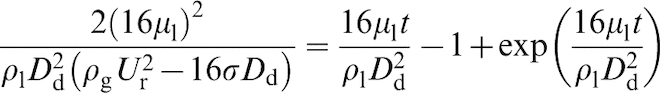
who studied the break up of drops in an air stream. His analysis was only qualitative, taking into account the effects of viscosity and surface tension. According to Gordon, the air pressure at the front of the drop causes a cylindrical plug to be extruded, while the surface tension, viscosity and inertial forces of the drop retard this process. The break up is caused by the stagnation pressure of the air (1/2) ρgUr2. During break up the surface area of the drop increases and this requires additional energy. If the radius of the cylinder is r, then the additional energy needed for the formation of both the two areas on the sides of the cylinder is 2(2πr) σ. The pressure on each of the sides of the cylinder is equal to 4σ/r and if we set r = Dd/2, Dd being the drop diameter, the resisting pressure due to surface tension is 8σ/Dd. Assuming that the length of the cylinder is approximately equal to the diameter of the drop, the viscosity force counteracting break up would be 16 μlUc/Dd, where Uc is the velocity of the centre of the cylinder. The acceleration of the droplet can then be calculated by combining the three pressures
The break up of drops exposed suddenly to a high velocity air stream in the laminar boundary flow region, i.e. 103<NRe<2×10⁵, for flow over a sphere, was also studied by Haas. 39 High speed photography was used to determine the characteristics of the break up mechanism of mercury. Under the conditions in question, a droplet was deformed due to the non uniform pressure normal to its surface. If the distortion was severe enough to overcome the effects of liquid surface tension and liquid viscosity, the globule will break if its size was larger than one designated as the critical one. In an analysis quite similar to that of Hinze, 22 Haas concluded that three dimensionless groups could give an adequate description of the problem. These were the Weber number, a viscosity group containing only the properties of the liquid and the gas phase Reynolds number.
For values of the Weber number ranging between 6 and 30 the mechanism of drop break up was that of the ‘inverted bag’ type. At NWe = 30 a transition was observed to a more chaotic break up mechanism. Based on experimental observations the maximum possible deformation, n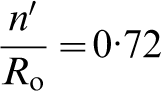
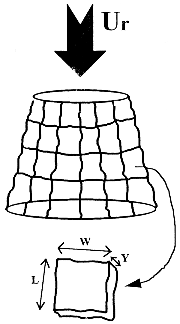
bag break up mechanism. The droplet took the shape of a hollow bag attached to a circular rim. Then, the bag burst producing a shower of finer drops while the rim broke up into larger droplets comprising 3/4 of the liquid in the initial drop. Ünal 38 suggested that this mechanism was probably caused by pressure drag. This break up mechanism is depicted in Fig. 7
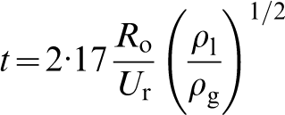
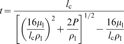
stripping break up mechanism. When the gas velocity was much larger than the critical break up velocity the initial drop formed a convex surface to the gas flow. The edges of this shape were drawn out into a thin sheet and finally broke up into smaller drops, as shown in Fig. 8. Friction drag was suggested to be the driving force for this mechanism. The stripping mechanism was found to operate in the range 71<NWe<179. This mechanism is the most probable to occur at the first stages of secondary disintegration in HPGA. For a Nitrogen atomizing velocity of 500 m s−1, Ünal 38 calculated the break up time t of a 500 μm droplet to approximately equal to 100 μs, using equation 24 by Gordon. 37 The observations by Ünal 38 on the atomization of Al showed the same trends when compared to analysis by Gordon. 37 However, Gordon's theory was found to underestimate the break up time by a factor of up to eight.
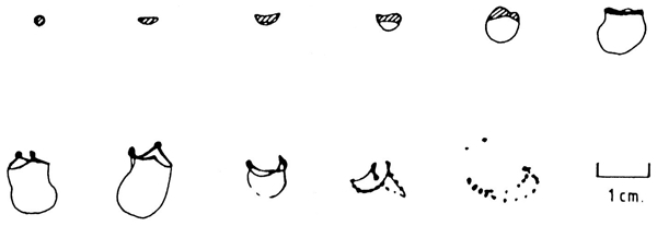
Secondary drop disintegration: bag break up mechanism 38
Secondary drop disintegration: stripping break up mechanism 38
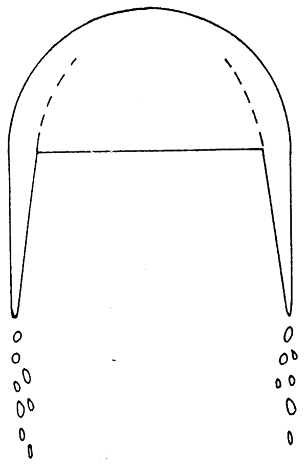
In contrast to the majority of the theoretical efforts to quantify secondary break up of drops, Wolfe and Andersen
23
presented an analytical model aimed to offer some insight to the mechanism of aerodynamic drop disintegration, both of the bag and stripping mode. The model assumed a cylindrical shape of the initial drop. To calculate the break up time, an outer layer having the form of a hollow cylinder was assumed to be sheared away from the main liquid body under the influence of the gas drag and the liquid surface tension and viscous forces. The total pressure responsible for break up of a drop was calculated as
Sketch to explain Wolfe and Andersen 23 model of drop disintegration
Surface wave formation
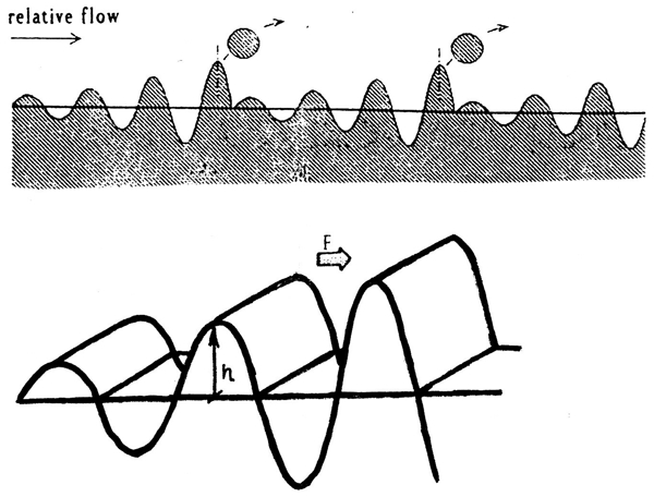
There has been a broad acceptance of the formation of wave instability on the surface of a melt during gas atomization as the predominant mechanism of disintegration. In most cases, the surface wave is assumed to have a symmetric or antisymmetric behaviour, see Fig. 10, and is thought to propagate along the direction of the relative velocity with a finite phase velocity.
Symmetric and antisymmetric modes of surface oscillation 27
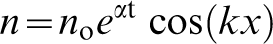
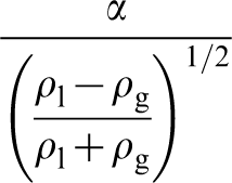
The behaviour of two superimposed fluids of different densities accelerated in a direction perpendicular to their interface is a classic example of the earlier efforts to quantify SWF mechanisms. The case studied by Taylor 40 is shown in Fig. 11. The starting point of the SWF theory is that if finite disturbances are formed on the interface between the two fluids they could be expected to increase exponentially under certain flow conditions, if their height is small compared to the wavelength of the disturbance.
Instability of liquid interface as studied by Taylor 40
The driving force for the transition of the interface from stability to instability is a downward acceleration of the fluid greater than that of gravity. The elevations of the disturbances n on both the upper and lower side of the interface were thought to be of the form
The formation of fast growing surface waves of viscous liquid sheets ejected into an incompressible gas medium, with particular reference to those produced by fan spray nozzles, was also followed by Dombrowski and Johns.
24
They concluded that the primary cause of instability was the interaction of the liquid sheet with the surrounding atmosphere. Experimental results indicated that when the wave amplitude reached a critical value, fragments of the sheet would be torn off and, under the effect of surface tension, contract into unstable ligaments. These ligaments subsequently broke down into droplets. For the mathematical formulation of an analytical solution to the SWF principle, a discrete liquid surface element was considered, upon which acted the gas force, the liquid surface tension force
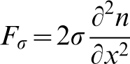

Instability of liquid interface as studied by Dombrowski and Johns 24
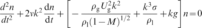
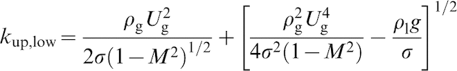
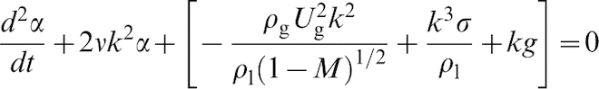
The atomisation of liquid sheets ejected from fan spray nozzles is quite different to the disintegration of a liquid column interacting with high velocity gas jets, as is the case in HPGA. Liquid sheets disintegrate through a stripping of their edges as well as a break down of the main body due to perforations at random areas along their surface, as shown in Fig. 13. Liquid columns during HPGA, on the other hand, break down in a different mode, which could be theoretically described by the SWF theory as formulated by Bradley,
26
who studied the atomization of liquid streams by high velocity gases. The treatment by Bradley
26
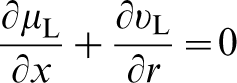
assumed a stationary liquid layer of infinite depth interacting with an incompressible and inviscid gas phase flowing parallel to the layer's surface, shown in Fig. 14. The motion of the layer's surface was described by the Navier-Stokes equations in their two dimensional form
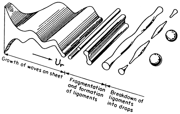
Typical disintegration mode of liquid sheet 24
Instability of liquid interface as studied by Bradley 26
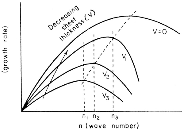
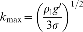
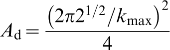
Growth rate of surface wave as function of its wave number 26
Footnotes
Acknowledgements
The author gratefully acknowledges funding from the EPSRC, UK, towards completion of this work as well as guidance and support by the staff of the Department of Materials Science and Engineering, University of Surrey, UK.