
Abstract
In the past few decades, stationary solid oxide fuel cell (SOFC) systems have been developed that can generate electricity and heat from the energy stored in hydrogen or hydrocarbons with total efficiencies up to 95%. While the mechanical cell support of stationary systems is commonly supplied by thick ceramic cell components (i.e. anode and electrolyte supported concepts), mobile systems demand a more robust design. This is ensured by a strong yet porous metallic substrate which serves as the mechanical backbone of thin film membrane electrode assemblies [metal supported cell (MSC) concept]. Porous PM Fe–Cr oxide dispersion strengthened alloys for use as MSC supports have recently been developed. These materials provide mechanical and chemical long term stability in typical SOFC atmospheres at operation temperatures up to 850°C. The substrates support a multilayer anode–electrolyte–cathode thin film assembly, constituting a high performance MSC repeat unit. These units are the building blocks for MSC stacks with superior properties for mobile applications.
Keywords
Introduction
A fuel cell is an electrochemical device which converts chemical energy directly into electricity without mechanical paths.1,2 For that reason, it is considerably more effective than internal combustion and can reach electrical efficiencies in excess of 60%. 1 Today, solid oxide fuel cells (SOFCs) are commonly used in stationary systems to generate electricity and heat. Figure 1 shows the principle of an SOFC.
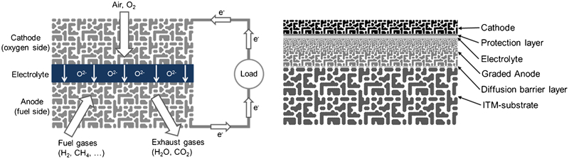
Principle of SOFC (left) and cross-section of MSC (right)
The basic structure of an SOFC is rather simple and consists of two porous electrodes that are separated by a gas tight electrolyte.3–5 In operation, air or pure oxygen is fed to the cathode side, and fuel (H2, CH4 or diesel reformate) is fed to the anode side.4,5 The electrolyte, typically 8YSZ (8 mol.-%Y2O3 doped ZrO2), conducts O2− ions and is almost non-conducting for electrons, at operation temperatures between 600 and 1000°C.6,7 Driven by the different oxygen partial pressure (basically the different oxygen activities at the cathode/electrolyte and anode/electrolyte interfaces) between cathode and anode side, O2− ions migrate through the electrolyte, whereupon fuel is oxidised at the anode and oxygen is reduced at the cathode. This generates an electron gradient between the anode and the cathode, i.e. a cell potential in the order of 1 V.3,6,8 In practical applications, a multitude of cells is connected to achieve technically attractive voltages. 6 In field tested stationary SOFC systems, either an electrolyte with a thickness of 100–200 μm constitutes the backbone of the cell3,6 or an anode substrate based cell is used (e.g. Topsøe fuel cells, Denmark or Versa, Jülich). To reduce the ohmic resistance of that ‘thick’ electrolyte, high operation temperatures up to 1000°C are employed. 6 Since the ceramics are mechanically unstable in fatigue controlled environments and a high operation temperature is unattractive, an improved cell agreement has been designed for mobile applications. This new cell design, a metal supported solid oxide fuel cell (MSC), is more complex than the basic structure of an SOFC and is schematically pictured on the right side in Fig. 1. The most difficult process in MSC development is the gas tight separation of the anode from the cathode side by a thin film electrolyte. This focus of the work reported in the present paper is the manufacture of the electrolyte by a physical vapour deposition (PVD) gas flow sputtering (GFS) process.
Experimental
Porous metal substrate
The load bearing part of the MSC, manufactured from a PM oxide dispersion strengthened Fe26Cr(Mo,Ti,Y2O3) alloy (Plansee trade name ITM), is highly porous (∼45 vol.-% porosity) and has a thickness of about 1 mm (Fig. 2).
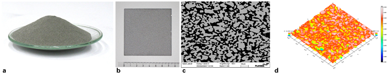
Porous metal ITM substrate a ITM powder [Fe–26Cr (Mo, Ti, Y2O3)]; b porously sintered ITM plate; c SEM cross–section of a porous ITM substrate; d surface roughness measured by optical method
This investigated ITM material fulfills several requirements:
the porosity of the substrate ensures sufficient gas permeability to support the anode layer with fuel gas on the one hand and to remove exhaust gases on the other hand
the porosity is stable in reducing anode atmospheres up to 850°C for several thousand hours; furthermore, the substrate shows high creep strength to ensure structural stability
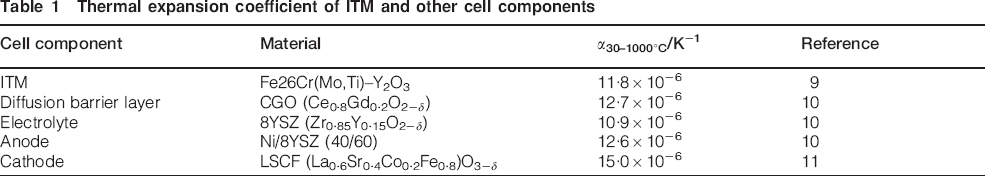
since ceramic layers withstand only small tensile stresses and the cells will be heated up to operation temperatures of 850°C, the thermal expansion coefficient (CTE) of the substrate must match the CTE of the ceramic cell layers as closely as possible to avoid cracking; the CTEs of ITM and common cell layers match reasonably well, as shown in Table 1
to avoid ohmic cell losses, the substrate must be highly electrically conductive in oxidising and reducing atmospheres at temperatures up to 850°C for long operation times; especially, the oxide layer growth in oxidising atmospheres should be as low as possible.
in oxidising atmospheres, Cr evaporation poisons the cathode; therefore, the Cr evaporation rate must be as low as possible too. To reduce Cr evaporation further, it can be coated with a protective layer (e.g. a ceramic perovskite).
Thermal expansion coefficient of ITM and other cell components
Metal supported cell
The components of the electrochemical cell are deposited onto the porous ITM substrate by the following procedures (Fig. 3).
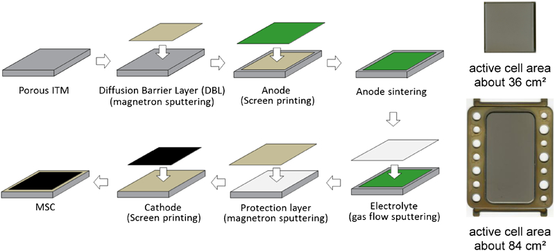
Manufacturing route of MSC (left), planar MSC design (top right) and integrated MSC with separated gas distribution (bottom right)
First, a 1–2 μm gadolinium doped ceria (GDC) diffusion barrier layer (DBL) is applied by magnetron sputtering to avoid diffusion of Cr or Fe into the subsequent anode layer and to avoid diffusion of Ni from the anode layer into the ITM substrate.
On top of the GDC-DBL, a 40–60 μm anode layer (Ni/8YSZ composite) is deposited by a sequence of three subsequent screen printing and sintering processes. In each screen printing/sintering film, the pore size is reduced, until finally a sufficiently flat anode surface is achieved. This is mandatory for depositing an essentially defect free thin film electrolyte with high gas tightness.
Then, a 4–5 μm thin film electrolyte is deposited by a PVD GFS process. The 8YSZ electrolyte must be as gas tight as possible to ensure a high oxygen potential difference between anode and cathode.
Onto the electrolyte, a GDC protection layer is deposited again to avoid a chemical reaction (e.g. the formation of SrZrO3)12,13 between the electrolyte and the cathode.
Finally, the cathode layer is screen printed. The cathode material of choice is LSCF (La1−xSrxCo1−yFeyO3−δ), which is activated during initial cell operation at 850°C (i.e. is not sintered separately).
Currently, two cell designs are available: a simple planar MSC with an active cell area of about 36 cm2 and an integrated MSC with separated gas distribution and an active cell area of about 84 cm2. Based on the metal substrate, arbitrary MSC forms can be cut out by laser.
Electrolyte manufacturing
As elaborated above, the gas tight thin film electrolyte (material: 8YSZ) is the core of an MSC. It is deposited by GFS. This process has been developed at Fraunhofer Institute for Surface Engineering and Thin Films (Braunschweig, Germany) and has several advantages compared to other PVD processes (e.g. high deposition rate and high process pressure).14–17 Based on these advantages, short process times can be realised. In Fig. 4, the cross-section of a GFS source is shown.
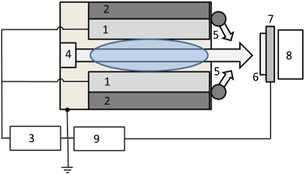
Two plane parallel water cooled (2) metallic Zr–Y targets (1) are arranged face to face and set on cathode potential via a source generator (3) such that a hollow cathode is formed and a hollow cathode glow discharge can be achieved. On the back of the source, Ar is fed in which streams through the source to the substrate (6). For reactive coating, the reactive gas is fed outside the source (5) and does not reach the metallic targets, i.e. the source is designed for reactive coating from a geometric point of view. To achieve various coating structures, the substrate holder (7) can be set on bias potential via a bias generator (9) and heated on demand (8).
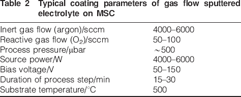
Based on the porous anode structure, a specific electrolyte thickness is necessary to seal the anode and in order to reach the required O2 concentration difference between anode and cathode. In this work, electrolytes with thicknesses of 4–5 μm were deposited. Typical electrolyte coating parameters are summarised in Table 2.
Typical coating parameters of gas flow sputtered electrolyte on MSC
Results and discussion
Figure 5 displays the cross-sections of a half cell MSC without the cathode. The coarse grained particles of the ITM substrate are coated with a GDC-DBL. Onto that DBL, the gradient anode structure is deposited, in which the pore size decreases continuously up to the anode/electrolyte interface. The 4 μm electrolyte is applied by GFS and seals the anode pores. The second DBL, applied by magnetron sputtering, is visible on top of the electrolyte. The final cathode is not shown in Fig. 5. A high resolution SEM image of a standard 8YSZ electrolyte and an X-ray diffraction (XRD) pattern of the electrolyte/anode compound are shown in Fig. 6.
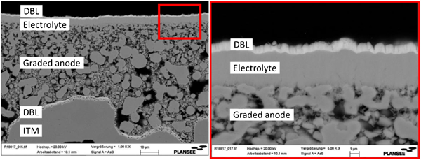
Cross-sections of half cell MSC (without cathode layer)
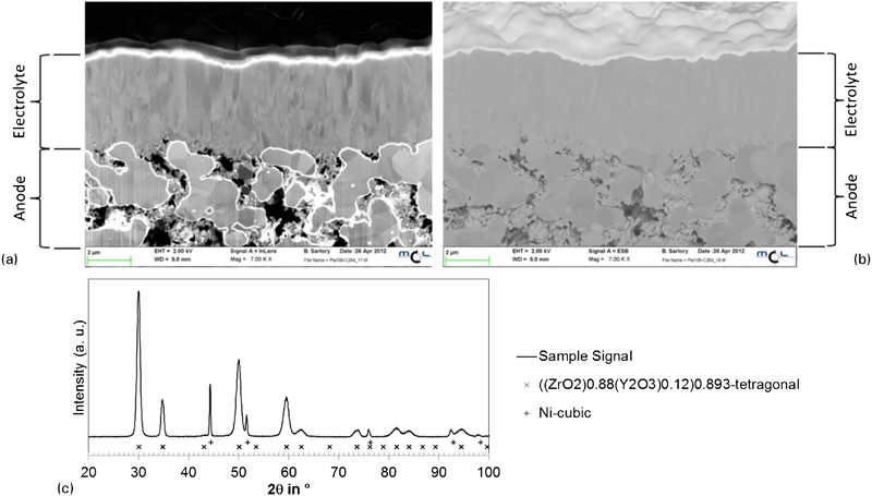
Image (SEM) of 4 μm 8YSZ electrolyte
Generally, a 4 μm electrolyte seals the porous anode sufficiently well, such that a gas leakage rate of 1·57×10−2 Pa dm3 s−1 cm−2 is achieved (measurement area, 22·3 cm2, Δp = 10 kPa, room temperature). The XRD pattern reveals a tetragonal 8YSZ structure, superimposed by the electrolyte and the anode underground and a Ni peak form the anode underground. Since the tetragonal 8YSZ structure is O2− conductive, the deposited electrolyte should perform from this point of view.
If the surface structure of the anode is homogenous, and contamination does not occur, the anode can be readily sealed by a GFS electrolyte. Where manufacturing flaws exist within the anode or when surface contamination occurs, those defects will tend to be reproduced in the electrolyte structure. This prevents the electrolyte from becoming gas tight. Furthermore, it should be recalled that the morphology of crystals in the GFS layer is columnar (cf. Fig. 7a), which facilitates the occurrence of defects along grain boundaries and obstructs gas tightness of the electrolyte.
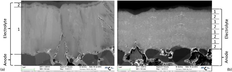
Electrolyte assembly of a 3·5 μm YSZ layer (1) with 500 nm metallic top layer (2) and b eight alternating layers consisting of 500 nm YSZ layers (1) and 500 nm metallic Zr/Y films (2)
For the latter reason, an electrolyte featuring a sequence of thin films with alternating columnar and planar structures was developed (Fig. 7b). The idea is to increase the sealing performance by introducing planar rather than columnar structures into the electrolyte. This is achieved by depositing metallic Zr/Y films with an equiaxed rather than a columnar morphology between the YSZ layers (cf. Fig. 7b). The structure can be processed by the alternating deposition of 8YSZ films and metallic Zr/Y films, each with a thickness of ∼500 nm respectively.
The compound electrolyte is generated by toggling the reactive gas on and off during sputtering while keeping all other parameters unchanged. The switching between metallic and reactive film deposition is a design related capability of the GFS source (Fig. 4). Since metallic layers do not conduct O2− ions, the electrolyte must be baked after the sputtering process in an oxygen atmosphere such that the metallic Zr/Y layer transforms into 8YSZ. Thereby, the metallic films undergo an expansion in volume. 18 That volume expansion is accounted for, i.e. the metallic layers are thinner than 500 nm to avoid the development of tensile stresses that would damage the electrolyte. The baking is not a separate process but happens during the initial heat up of the cell. It turns out that the bimodal structure reduces the permeability of thin film electrolytes significantly.
The electrolyte in Fig. 7a contains a 3·5 μm oxide layer and a 0·5 μm metallic top layer, i.e. the electrolyte has a total thickness of about 4 μm. In Fig. 7b, the electrolyte consists of an eight layer array, where 0·5 μm metallic and oxide films are deposited alternately as described above. With the latter electrolyte structure, leakage rates of 2·9×10−2 Pa dm3 s−1 cm−2 are achieved (measurement area 22·3 cm2, Δp = 10 kPa, room temperature). The electrolytes of Fig. 7 were characterised electrochemically as shown in Fig. 8, where a characteristic V/I curve is displayed for the 4 μm electrolyte from Fig. 7a.
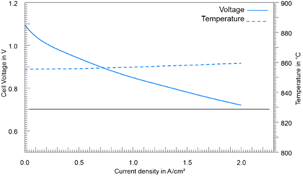
V/I characteristics of MSC manufactured with compound electrolyte (3·5 μm oxide layer+0·5 μm metallic top layer): T = 850°C; 0·25 NL min−1 air on cathode side; 0·25 NL min−1 H2 on anode side; measurement area 1 cm2
The V/I curve was recorded at a temperature of 850°C with 0·25 NL min−1 air on cathode side and 0·25 NL min−1 H2 on anode side. The cell features an open voltage (OCV at 0 A cm−2) of 1·096 V and a current density of >2 A cm−2 at 0·7 V, i.e. a powder density of >1400 mW cm−2. Given these results, it is obvious that MSCs with compound electrolytes have a high potential for mobile applications.
Conclusions
A porous metal substrate (ITM) for use as a backbone for MSCs has been developed. Onto that backbone, a thin film electrochemical cell was deposited by suitable technologies, including PVD, screen printing and sintering processes. An oxide thin film electrolyte, deposited by GFS, separates the porous anode from the porous cathode. If the anode structure contains flaws or surface impurities, the oxide electrolyte growth is not able to seal ‘large’ subsurface defects. For that reason, compound electrolytes, comprising alternate metal/oxide sublayers, were deposited, and based on the different grain morphology of metallic and oxide layers, a much improved sealing performance is achieved. Metal supported cells with improved electrolyte structure were tested electrochemically and exhibit superior current densities >2 A cm−2 at 0·7 V.
Footnotes
Acknowledgements
The authors would like to thank Dr A. Weber of the Karlsruhe Institute of Technology for the electrochemical characterisation of the cells.