
Abstract
Rolls-Royce has successfully established a capability for the hot isostatic pressing (HIP) of austenitic stainless steels in nuclear plant. The focus has now been extended to HIP of nickel based alloys, whose good material properties make their use in plant increasingly attractive. A development programme has been undertaken, comparing the mechanical property behaviour of HIP Alloy 600, 690 and 625 with their wrought counterparts. The results are promising, showing acceptable tensile properties and Charpy impact results for the HIP test pieces that are comparable to, or better than, the wrought data. It is concluded that HIP offers an attractive alternative manufacturing route that is ideal for the production of a small number of high integrity components. Hot isostatic pressing microstructures have the advantage of being isotropic and equiaxed, with uniformly fine grain sizes; properties not normally found in thick-section forgings.
Introduction
Hot isostatic pressing (HIP) is an attractive alternative manufacturing route, offering improved mechanical properties, better control of defects and reproducible results. Turnaround from order to completed component can also be significantly reduced when compared to a forging.1,2
Hot isostatic pressing was initially used as a means to consolidate porosity in castings to improve their mechanical properties. The process is also used to consolidate metallic powder into a fully dense part. It is also possible to produce near net shape components and more complex geometry components that are fully dense and require minimal machining. Production of near net shape items from powder can deliver cost savings by reducing initial material usage and subsequent machining costs. Powder production and HIP processing can also be used to provide protection against forging route obsolescence. Setup costs are lower and batch sizes smaller, particularly well suited to small numbers of high integrity components; such is the requirement in the naval nuclear sector.
Hot isostatic pressing powder microstructures have a number of positive attributes. Typically, they are isotropic and equiaxed, with a small grain size. The grain size is often found to be uniformly fine, a property not normally achieved in heavy section components. This helps facilitate ultrasonic NDE examination. Additionally, it is found that inclusions are less common and of a more benign geometry, so easing fracture assessment.
The starting material for the powder HIP (PM-HIP) process is normally a high quality, gas atomised powder, uniform and spherical, and which contains low levels of impurities such as oxygen. The powder particles are formed very rapidly and are characterised by very low levels of segregation; this gives predictable behaviour with regard to shrinkage and flow properties during HIP.
The final component shape is achieved by making a thin steel can of the required dimensions in order to hold the powder. An allowance of around 30% is made in order to accommodate the shrinkage occurring during the HIP process. In this way, complex shapes can be created, incorporating features not normally possible using more conventional casting or forging methods. This may enable welds to be removed from the design, simplifying construction and subsequent NDT requirements. This is an advantage as welds are a major source of residual stress, which can drive both fatigue and stress corrosion cracking mechanisms.
Rolls-Royce HIP capability
Rolls-Royce has supplied pressurised water reactor (PWR) plant components, mainly forgings, for over 50 years. To provide an alternative strategic sourcing route for these PWR components, which have wall thicknesses of up to 125 mm, Rolls-Royce has developed and applied its experience in the design, specification, procurement, and justification of components produced by the HIP route.
The developments started with the HIP bonding of hardwearing seats into small-bore valves, but since then have focused on the HIP consolidation of powder for a number of structural pressure boundary components, subjected to typical PWR pressures, temperatures and environments.
Hot isostatic pressing bonding and powder consolidation were already established manufacturing processes used in many industries around the world. 3 However, the use of the technology in the nuclear sector is not common, possibly due to conservatism in the industry and the requirement to use established and well proven technologies.
The regulatory requirements that apply to nuclear components for the introduction of a new manufacturing process are captured mainly in three Safety Principles:
proven engineering practices: nuclear power technology is to be based on engineering practices which are proven by testing and experience
equipment qualification: safety components and systems shall be chosen which are qualified for the environmental conditions
continuous improvement: operating organisations and designers shall seek to improve safety standards and safety performance in present and future plant. Techniques such as maintaining excellent material condition and component performance should be employed.
To satisfy the Safety Principles a gradual introduction strategy for HIP components evolved, which enabled the proving of the technology for specific applications, and the development of the specification, procurement and justification experience.
The key elements of this evolution were:
to demonstrate by mechanical testing to recognised standards that HIP material is equivalent to the wrought form
to obtain manufacturing and in-service experience of the technology through HIP of non-pressure boundary components, for example, small bore valve seat inserts
to develop further manufacturing and in-service experience of the technology by applying it to leak limited pressure boundary, isolable components, such as welded toroid seals
to further development of manufacturing and in-service experience of the technology by applying it to isolable pressure boundary components, such as the steam generator headers and pipe-work
finally, to apply the technology to un-isolable pressure boundary components, including pipe-work.
For all of the above, technology demonstrators were produced to demonstrate that the geometric shapes, material properties and required quality assurance could be achieved. The demonstration of the design justification used the UK Technical Advisory Group on Structural Integrity multilegged approach 4 for the provision of a component safety case covering:
Leg 1 – design and manufacture
Leg 2 – functional testing
Leg 3 – failure analysis
Leg 4 – fore-warning of failure.
It was considered that the predominant consideration in the introduction of the HIP process was the demonstration of a robust, quality assured manufacturing process in relation to Leg 1, and an understanding of the possible defects in relation to Leg 3 – failure analysis.
Numerous material samples and prototype components were tested to cover batch to batch and component geometry effects. Comparison was made where possible with the performance of a wrought comparator and a range of mechanical, metallurgical, welding behaviour and corrosion tests were undertaken. This work showed that HIP material has at least equivalent mechanical and metallurgical properties to wrought material.
HIP hardfaced valve seats and stainless steels
The first Rolls-Royce application of the HIP process was the manufacture and subsequent bonding of the hard facing material Stellite 6 into austenitic stainless steel small bore globe valves. The process has been in production since 1994. A key benefit of the process was the achievement of the improved grain structure for the Stellite seat. This has resulted in a reduction in the non-conformance and the removal of a bottleneck in the production route for small-bore globe valves.
The next application of the HIP process was for the production of thin walled toroid pressure seals, which requires material to be of the highest possible material cleanliness. Hot isostatic pressing consolidated 316 stainless steel powder was identified as a suitable material supply route; it offered smaller defect sizes allied with an ability to supply the small material quantities required to an acceptable cost and lead-time. Since 2003, over 500 toroids have been manufactured by this route with approximately 200 being in-service and the longest time approaching 10 years.
Use within a major pressure boundary component then followed. Traditionally, this had been manufactured from large 316 stainless steel forgings comprising a central tee with welded end caps. Forging of the tee uses a three ram press and closed die process. Typical issues experienced with the forging process included large grain structures and surface-breaking defects. Hot isostatic pressing manufacture by powder consolidation presented an attractive alternative to the forging route: In addition to project savings, the resultant HIP components offered advantages in terms of material properties and an improved inspectability, which has enabled changes to the component geometry. Production components were introduced in 2009 and became the first Rolls-Royce application of HIP material in a primary circuit pressure retaining application.
More recently, an austenitic stainless steel technology demonstrator of a large bore pipe section has successfully enabled the elimination of some large bore welds and small bore stub connection welds. These developments were subsequently taken up and are in production for isolable pipe-work. At this time, the guaranteed size achievement required for pipe-work shapes, however, rules out sections where access cannot be gained for final machining and further work is planned to address this. Other HIP programmes are in progress and these include the work on nickel based alloys reported here.
HIP nickel base alloys
Rolls-Royce began pursuing its interest in HIP nickel based alloys for nuclear based applications with the introduction of a valve body development programme in 1990. The interest in HIP nickel based alloys was twofold: the drive was part of a research programme to demonstrate the potential of the HIP process and also an opportunity to make use of new materials. The aim was to produce an Alloy 625 valve body, complete with stubs, seat and hard liner, in a single operation.
A review into potential new materials had identified Alloy 625 as having potential to offer benefits in a wide range of plant applications, mainly due to its favourable mechanical and corrosion properties. Areas where Alloy 625 is inferior to austenitic stainless steels are ductility and fracture toughness. The advantages of HIP were also explored, with a view to improving quality, enhancing material properties and cost reduction. The HIP processes are particularly attractive in the context of materials such as Alloy 625 which, as a result of the very properties which make them attractive to a designer, can be expensive to fabricate and machine. It was therefore decided to combine both materials and fabrication aspects in a single experimental project to demonstrate the feasibility of producing a component in Alloy 625 using HIP to show that cost savings could be achieved by combining several stages of production into a single operation.
A valve was chosen as the most suitable component for the exercise. Valves are commonplace in nature and the design offered a degree of complexity without being overambitious. It also offered the opportunity to combine a number of production stages into one: body machining, seat installation, addition of stubs and fitting of the liner.
The project was split into three sections: preliminary trials to establish the optimum conditions for the HIP cycle and provide test pieces for mechanical testing and metallographic examination, production of the valve bodies for machining trials and subsequent build and finally rig testing of a completed valve.
Valve production
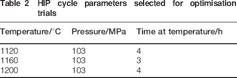
The chemical composition of Alloy 625 is 0·02C–0·37Si–21·3Cr–59·3Ni–4·36Fe–9·3Mo–3·53Nb–0·33Mn–0·15P–0·007S–0·04Co–0·003Al–1·05Ta–0·108N–0·021O (wt-%) The powder particle distribution of the powders is shown in Table 1. Three HIP cycle temperatures were tested for the process of optimisation; the details of these HIP parameters are outlined in Table 2.
Powder particle size distribution of Alloy 625

HIP cycle parameters selected for optimisation trials
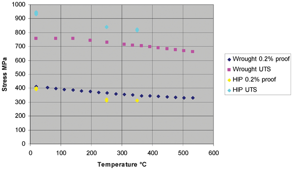
Initially, test bars produced from the Alloy 625 powder at each of the three HIP temperatures were assessed by metallographic examination and tensile testing. All testing was performed on the as HIP material. The metallographic examination failed to reveal any significant microstructural differences between the different HIP cycles, with all specimens appearing to be fully consolidated and microstructurally sound. Tensile testing showed that both the 0·2% proof stress and ultimate tensile strength (UTS) decreased with increasing HIP temperature (Fig. 1). Additionally, it was noted that three of the twelve specimens tested failed at extensometer knife edges, one such specimen was from the 1120°C cycle, whilst the other two were from the 1160°C cycle. Although the evidence was limited, it was concluded that the 1200°C cycle provided the best ductility and toughness and would be used for all subsequent HIP cycles throughout the project. It was also determined that the valve liner and seat materials were suitable for HIP processing at the same temperature.
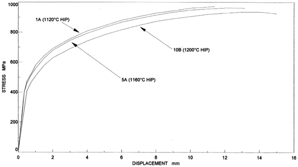
Tensile test results showing effect of HIP temperature
Three valve bodies were produced: one to provide test data material, one for machining trials and one was built up into a complete valve for rig testing. In each case, the can design was optimised as the shrinkage behaviour of the Alloy 625 during HIP was observed.
Rig testing of the valve was considered to be successful, with the valve operating smoothly during both hot and cold cycles of testing. When the valve was cut open after the test had been completed, it was found that there was no evidence of pickup or damage and very little discoloration.
The valve bodies produced during this exercise represented a major departure from the conventional method of producing such a component. The use of powder metallurgy, the introduction of new materials and the combination of a number of production stages into one HIP operation were all combined into a single experiment which should be seen as a demonstration of feasibility rather than a rigorous development exercise.
Material characterisation
In conclusion of the programme, an extensive materials characterisation programme was carried out on the first of the valves to be produced. This included mechanical, physical, weldability and corrosion properties and generally these were all similar to wrought Alloy 625. The discussion below focuses on the mechanical test results, including tensile, fracture toughness and fatigue testing.
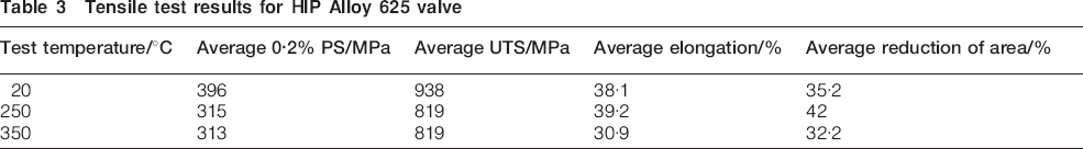
Tensile testing was carried out at three temperatures: ambient, 250 and 350°C. The results are summarised in Table 3. The data have also been compared with data for wrought material, as can be seen in Fig. 4. It can be seen that the UTS values meet the 2010 ASME Boiler and Pressure Vessel Code wrought design data requirements, but the 0·2% proof stress does not.
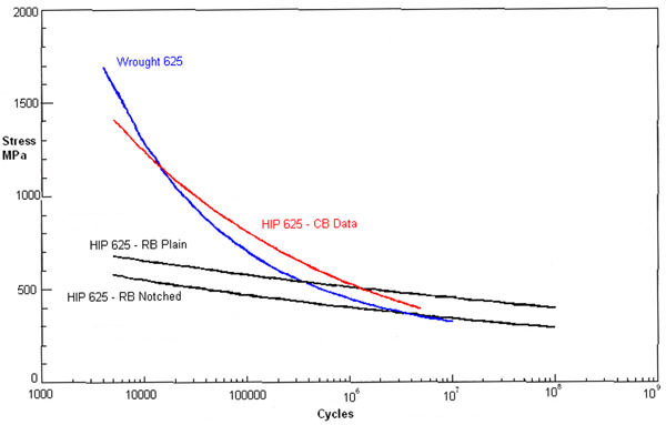
Fatigue test results for Alloy 625 valve. RB refers to data collected from rotating beam tests, whilst CB is for cantilever bend testing
Tensile test results for HIP Alloy 625 valve
Tensile test results for HIP Alloy 625 compared with ASME wrought design data 5
Compact tension fracture toughness tests were carried out. Owing to the limited amount of material available, only three fracture toughness test specimens were tested. However, the results were very consistent and combined to produce a single curve to the J–R data. From this fit, a value for KJ0·2 could be determined to be 157 MPa m1/2. This compared with equivalent wrought values (from a previous Rolls-Royce testing programme) of 206 MPa m1/2. The relative behaviour of the HIP and wrought forms of material is compared in Fig. 3. From the fracture toughness testing, it was concluded that the HIP material was inferior to the wrought Alloy 625 in terms of initiation and resistance to crack growth. However, the lower fracture toughness values were considered to be of little concern in this particular application and would be improved with further developmental work.
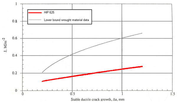
Fracture toughness data for HIP and wrought Alloy 625
Two types of fatigue testing were carried out: rotating beam tests for high cycle fatigue data and strain controlled cantilever bend tests to provide low cycle fatigue data. In total, 22 cantilever bend tests were carried out at a frequency of 5 Hz, both at ambient temperature and 350°C. Two types of rotating bend tests were conducted, one plain and one notched. The notch was designed to achieve a stress concentration factor of ∼3. Fifty rotating bend specimens were machined, 19 plain and seven notched were tested at room temperature and 15 plain and nine notched were tested at 350°C. The results are shown in Fig. 4.
At the high cycle end of the fatigue curve, agreement between the two different test methods is good. Because of their higher cycle frequency, the rotating bend test specimens dominate at the high cycle, low stress end of the curve. The cantilever bend tests give higher results at lower cycles owing to the decreasing stress on the remaining ligament as the crack grows under constant displacement.
The fatigue strength of the HIP material as determined by cantilever bend testing was found to be superior to that for wrought material. However, the difference was small and it is considered that, in the first instance, the design S/N curve for wrought material can be applied to the HIP material. The results from rotating bend tests compare closely to data for wrought material.
Despite the successes and thorough nature of the programme, no further development work has continued on the Alloy 625 valve, owing to a lack of interest in enhancing the design and committing to the extensive development work that would be required to transition the valve from an experimental programme to a prototypic valve. More development work would also have been required to explain the lower than desired mechanical properties of the HIP material.
Recent developments
Over the past few years, interest in HIP of nickel based alloys has been reignited, with the development of a number of small test programmes to demonstrate feasibility and characterise the mechanical properties, comparing them with their wrought equivalents. The nickel based alloys investigated to date are Alloy 600, Alloy 690 and Alloy 625.
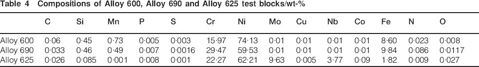
In the first phase of the work, 15 kg test bars of Alloy 600 and Alloy 690 were produced by HIP from nitrogen gas atomised powder. The chemical compositions are shown in Table 4. The HIP cycle was run at two temperatures, 1120 and 1150°C, to investigate the effect of HIP cycle temperature on the final mechanical properties.
Compositions of Alloy 600, Alloy 690 and Alloy 625 test blocks/wt-%
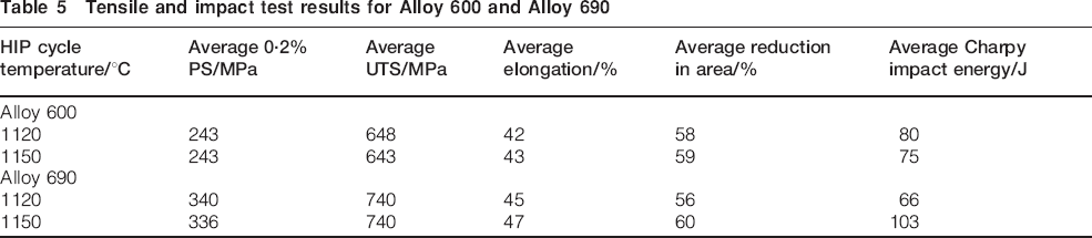
Tensile testing and Charpy impact testing were performed at ambient temperature on the test blocks. 6 The results are summarised in Table 5. Varying the temperature of the HIP cycle appeared to have very little effect on the tensile and impact properties of Alloy 600, but the impact properties of Alloy 690 were improved by increasing the HIP cycle temperature to 1150°C.
Tensile and impact test results for Alloy 600 and Alloy 690
A further materials characterisation programme including tensile testing, Charpy impact testing and microstructure was then carried out on the 1150°C HIP 600 and 690 materials. These results were compared with wrought ASME data, as shown in Figs. 5 and 6. 7 The HIP data exceeded ASME wrought data for both materials over the measured temperature range.
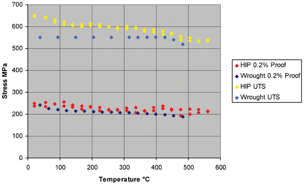
Comparison of Alloy 600 0·2% proof stress and UTS results (HIP cycle temperature 1150°C) with ASME wrought data9
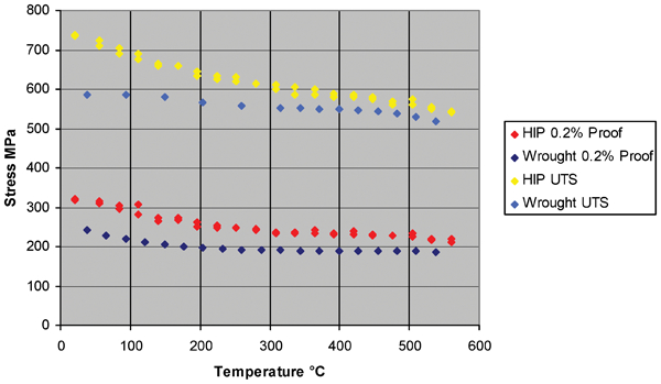
Comparison of Alloy 690 0·2% proof stress and UTS results (HIP cycle temperature 1150°C) with ASME wrought data9
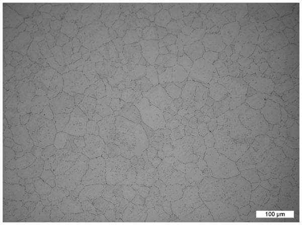
Alloy 600 microstructure electrolytically etched with 10% sulphuric acid
Both microstructures were generally equiaxed, with an ASTM grain size of 6 or finer. The cleanliness of the material seemed to be good, with few inclusions observed in the material and no evidence of prior particle boundaries. Microstructural images are shown in Figs. 7 and 8.
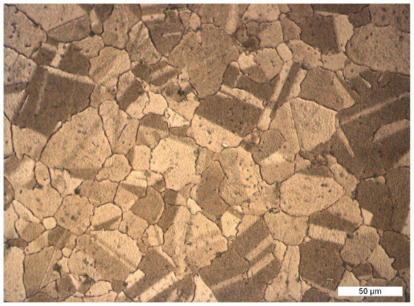
Alloy 690 microstructure following HIP at cycle temperature of 1150°C: electrolytically etched with bromine–methanol mixture
An additional requirement has added Alloy 625 to the list of materials. As before, a small HIP test block of approximately 15 kg was produced from nitrogen atomised Alloy 625 powder. The powder, this time, was 45±15 μm in size, smaller than that used for the HIP Alloys 600 and 690. The composition of the powder is given in Table 4.
The HIP conditions used were 1160°C and 103 MPa for 4 h. Following HIP, the test blocks were heat treated at 900°C for 1 h per inch and then air cooled. Initially, the powder was processed at a temperature of 1150°C (as in phase 1), but observations of porosity in the billet indicated that full consolidation had not occurred and the HIP cycle temperature was increased. It is thought that the lack of consolidation was due to the smaller size of the powder.
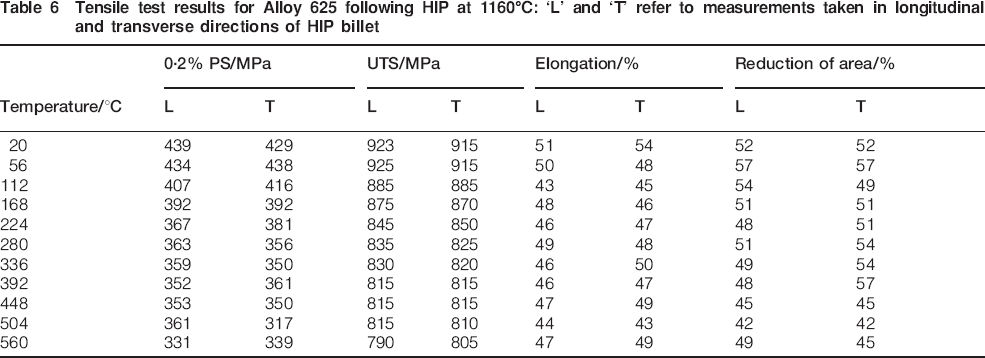
Tensile tests (at a range of temperatures) and Charpy impact testing were conducted on the test blocks. Measurements were taken in the longitudinal and transverse directions to confirm that orientation had no effect on the HIP material properties. These results are summarised in Table 6. The proof stress and UTS results from the tensile tests are compared with wrought ASME data 7 in Fig. 9. It can be seen that the UTS data achieves the ASME requirement by some margin, whilst the yield strength can be seen to be comparable with the ASME requirement.
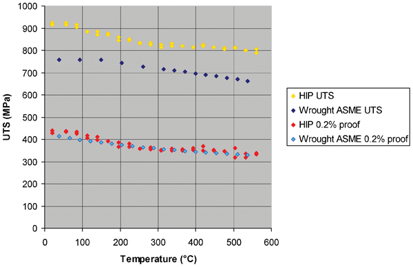
0·2% Proof stress and UTS of HIP and wrought9 Alloy 625 comparison
Tensile test results for Alloy 625 following HIP at 1160°C: ‘L’ and ‘T’ refer to measurements taken in longitudinal and transverse directions of HIP billet
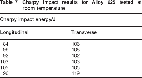
The Charpy impact test results, shown in Table 7, of between 84 and 119 J are considered to be favourable and consistent with earlier nickel based alloy results.
Charpy impact results for Alloy 625 tested at room temperature
The promising results of this initial testing have prompted the development of an internal specification for HIP of Alloy 625 and plan to process a range of larger components by HIP for further testing. The possibilities of comparisons with the earlier Alloy 625 work are limited, although improved tensile test results have been observed. It is unclear whether this is due to the tightening of the Alloy 625 composition, improvement of the HIP process or the influence of heat treatment. Additional research is continuing into the mechanical properties of HIP Alloy 625, with the view to introducing it onto plant in the future.
Conclusion
This paper has charted the progress Rolls-Royce has made in understanding the HIP process for both stainless steels and nickel based alloys. Since the development of HIP bonding of valve facings over 20 years ago, an extensive set of development programmes has been conducted to characterise a variety of powder materials. This has provided invaluable specification and process understanding that is required to justify the use of HIP components in high integrity applications.
Drawing on experience from the stainless steels work, a methodology has been established to take the HIP process from initial feasibility and development trials into design and through individual component safety cases. Evidence has been presented to demonstrate that the mechanical properties of optimised HIP Alloys 600, Alloy 625 and Alloy 690 equal or exceed the properties of equivalent wrought alloys.
It is hoped that a similar methodology will be followed for the introduction of Alloy 625 in nuclear plant applications.