
Abstract
Electroless Co–P coating was successfully applied on AZ31 magnesium alloy through environmentally friendly cerium–lanthanum–permanganate conversion coating treatment. It is found that application of the conversion coating activates the electroless Co–P plating. Electroless nucleation centres were first formed around the conversion coating pores due to replacement reaction between the cobalt ions and the alloying elements, and then were grown to form cobalt clusters. Low phosphorous, crystalline and compact electroless coating with no obvious pores or cracks in the coating/substrate interface was obtained. The results of open circuit potential and electrochemical impedance spectroscopy measurements showed that the corrosion resistance of the AZ31 alloy was significantly increased by electroless Co–P plating.
Introduction
Magnesium and its alloys have gained more attention as structural materials due to high strength/weight ratio, which makes them very attractive in some applications especially in aerospace and transportation industrial sectors. 1 AZ31 is the most widely used commercial magnesium alloy. 2 However, AZ31 and other magnesium alloys are extremely vulnerable to corrosion as a consequence of its very negative electrochemical potential (2·363 V versus standard hydrogen electrode). 3 Therefore, an appropriate surface treatment is necessary before any outdoor application of the AZ31 alloy. Electroless plating is known as an autocatalytic deposition process to apply uniform metallic coatings on different substrates. Application of Ni–P electroless coating on magnesium based alloys has been extensively investigated from different points of view,4–8 but there are no reports about the application of electroless Co–P coatings on magnesium or its alloys. Electroless cobalt films are interesting particularly with regard to their magnetic properties, but several other applications have been proposed. Electroless Co–Ni–P and Co–B coatings plated over Ni–P deposits showed better corrosion protection performance when compared to an equivalent thickness of the Ni–P alone in salt spray corrosion tests. Other important applications involve its hardness, wear resistance, electrical conductivity and thermal conductivity. 9 Electroless Co–P coating is a good candidate for corrosion protection of magnesium alloys since the cobalt is a metal with high anti-corrosion performance, but the corrosion resistance of electroless Co–P coating on magnesium alloys or other metallic parts has still not been sufficiently investigated. However, Song et al. 10 have investigated the application of Co–P films by electroless sono-deposition at low initial temperature and the effect of ultrasonic power on the corrosion protection performance of the final coating.
Electroless plating of the magnesium based alloys is difficult due to high chemical affinity of magnesium to aqueous plating solutions. In addition, the presence of different phases leads to electrochemical heterogeneity, which makes the situation even more complex. These problems can be minimised by application of suitable pretreatment before the final plating. Traditionally, the magnesium alloys are treated in hydrofluoric acid (HF) solution to form a magnesium fluoride conversion film before the final plating, but the HF is a very corrosive and dangerous chemical, which restricts its application. Different environmentally friendly pretreatments have been proposed for application of electroless Ni and Ni alloy coatings on magnesium alloys,11–14 but the application of Co–P electroless coating on magnesium based alloys has not yet been investigated.
The aim of this study is to investigate the application of the electroless Co–P coating on AZ31 magnesium alloys through the environmentally friendly cerium–lanthanum–permanganate (CLP) pretreatment. Morphology and chemical composition of the applied deposits have been studied by scanning electron microscopy (SEM) and energy dispersive X-ray spectroscopy (EDX) respectively, while X-ray diffraction (XRD) was used for phase analysis. Moreover, the corrosion protection performance of the coating has been studied by open circuit potential (OCP) and electrochemical impedance spectroscopy (EIS) measurements.
Experimental
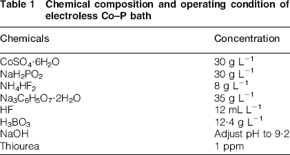
Specimens were cut from AZ31 magnesium alloy (with the nominal composition of 3 wt-% Al, 1 wt-% Zn, 0·2 wt-% Mn and balanced Mg) 3 with a size of 10 mm × 10 mm × 5 mm and then were polished by emery papers up to 2500 grit. First, the samples were degreased in an alkaline solution (10 g L− 1 Na3PO4.H2O and 40 g L− 1 NaOH) for 15 min at 60°C. Then, the samples were etched in an acidic solution (63 wt-%, 100 mL L− 1 HNO3 and 125 g L− 1 CrO3) for 30 s in order to create course surface that promotes the mechanical interlocking between the final coating and alloy substrate. In the next stage, the alloy substrates were treated in the CLP 13 conversion coating solution [0·4 g L− 1 La(NO3)3, 0·4 g L− 1 Ce(NO3)3 and 25 g L− 1 KMnO4] in room temperature for 30 min. Finally, the electroless plating was performed in the sulphate electroless plating bath at 95°C. Chemical composition and operating condition of the electroless bath are given in Table 1. The samples were rinsed in distilled water between each stage.
Chemical composition and operating condition of electroless Co–P bath
Surface and cross-sectional morphology of the coating together with the morphology of the conversion coated sample were studied by SEM (LEO, VP 1430) images, while the chemical composition of the treated alloy surface was studied by EDX (Vega-Tescan). Moreover, XRD (Philips Xpert) was used to phase analysis of the applied coating.
The OCP of the bare and coated samples was measured in 3·5 wt-% NaCl solution with respect to a saturated Ag/AgCl reference electrode. A conventional three-electrode cell including the bare or coated alloy sample as working electrode, a platinum sheet (1 cm2) as counter-electrode and a saturated Ag/AgCl reference electrode was used for EIS measurements. EIS tests were carried out at OCP condition within the frequency range of 100 kHz to 0·01 Hz using a sine wave of 10 mV amplitude peak to peak.
Results and discussion
Activation of electroless plating
Figure 1 shows the SEM image of the alloy surface after 30 min pretreatment in the CLP conversion coating bath at two different magnifications. As it is clear, a porous conversion film is formed more probably due to continuous hydrogen gas evolution during the process that impedes the formation of complete conversion film. The CLP conversion coating mechanism and its chemical composition have been previously investigated.5,14 The CLP conversion film is mainly composed of cerium, lanthanum, manganese and magnesium oxides. Despite the porous nature, this film can considerably decrease the chemical activity and electrochemical heterogeneity of the alloy surface. The CLP conversion coating plays a key role in the subsequent electroless plating since the electroless plating can be activated after CLP film application through a specific mechanism that will be discussed below.
SEM image of alloy sample after conversion coating treatment at two different magnifications: a 1000 × ; b 15 000 ×
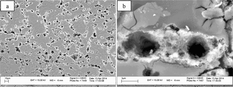
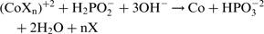
First, it should be noted that the magnesium alloys have not been directly activated in conventional manner with Pd+2 ion containing acidic solution because magnesium is a very reactive metal and it can severely corrode in the presence of the Pd+2 ions. Therefore, other activating procedures such as HF treatment have been developed. Application of HF treatment should be restricted due to its harmful effects as mentioned above. Therefore, the CLP conversion film is used instead of the conventional HF treatment in this study. Figure 2 shows the surface morphology of the CLP treated alloy surface after 10 min (Fig. 2a) and 30 min (Fig. 2b) plating in electroless bath. As it is clear from Fig. 2a, the cobalt nucleation centres have been formed near the edge of the pores in conversion coating, but there are no nucleation centres on the central areas of the pores or on the pore free regions. The nucleation centres have been created due to electrochemical substitution reaction between the cobalt ions in the plating solution and the alloying elements (Mg, Al and Zn) on the bottom of the conversion film pores since the electrochemical potential of the cobalt is more positive than the mentioned elements:


 ) at the bottom of the pores. Figure 2b shows the morphological image of the CLP treated alloy surface after 30 min electroless plating. It is obvious that the cobalt nucleation centres have been grown to form clusters around the internal edge of the pores. The clusters are grown in either vertical or horizontal directions to form the final Co–P coating. The mechanism of autocatalytic plating after the formation of nucleation centres can be described as follows:
10
) at the bottom of the pores. Figure 2b shows the morphological image of the CLP treated alloy surface after 30 min electroless plating. It is obvious that the cobalt nucleation centres have been grown to form clusters around the internal edge of the pores. The clusters are grown in either vertical or horizontal directions to form the final Co–P coating. The mechanism of autocatalytic plating after the formation of nucleation centres can be described as follows:
10


SEM image of CLP treated alloy surface after a 10 min and b 30 min plating in Co–P electroless bath
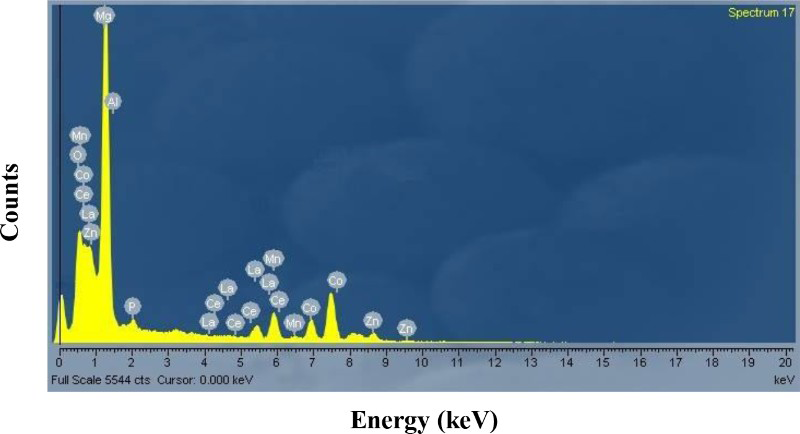
Spot EDX analysis on cobalt clusters formed in CLP film pores after 30 min electroless plating
Characterisation of Co–P coating
The cross-section area of the coated samples after different plating times have been shown in Fig. 4. Evidence of non-continuous metallic layer can be easily observed after 1 h plating preferentially on the surface defects of the substrate, as shown in Fig. 4a. The electroless coating has been adequately thickened after 3 h to cover the whole alloy surface. The average thickness of the coating after 3 h electroless plating is ∼15·2 μm, which is approximated by two different points on the related cross-section image (Fig. 4b). The produced coating is completely attached to the substrate, and there is no crack or defect in the applied cobalt matrix. The coating thickness increases to ∼24·6 μm when the plating time increases to 5 h, but the cross-section morphology does not change (Fig. 4c). In addition, the coating shows a much more uniform thickness over the alloy substrate when the plating time is increased.
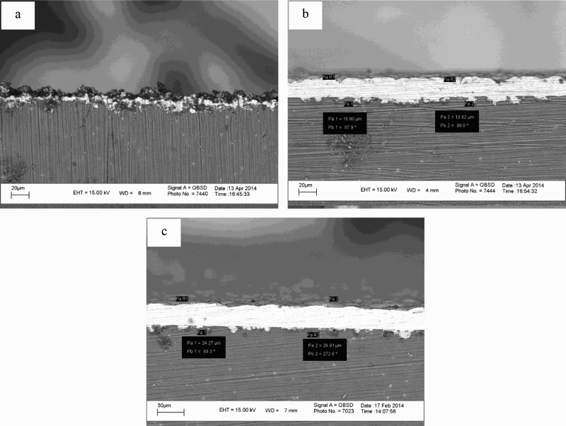
Cross-section morphology of Co–P coating after a 1 h, b 3 h and c 5 h electroless plating
Figure 5 show the surface morphology images of the final Co–P coating at two various magnifications. Moreover, the spot EDX analysis of the surface is given in Fig. 5c. Formation of crystalline structure with random orientation of crystals can be easily observed at 15 000 × magnification (Fig. 5b). EDX analysis revealed that low phosphorous coating was formed, which contained ∼1·76 wt-% phosphorous and >98 wt-% cobalt. It is considered that the full crystalline structure is related to the low phosphorous content of the coating. Examination by XRD (Fig. 5d) revealed a hexagonal close packed (hcp) crystalline structure for cobalt in the low phosphorous electroless coating since there are three sharp peaks at 2θ = 41·80°, 2θ = 47·55° and 2θ = 75·95°, which are related to 100, 101 and 110 hcp Co structure respectively. 15 It is accepted that the low phosphorous electroless cobalt coating has hcp crystalline structure, but the face centred cubic structure becomes dominant with increasing the phosphorus content of coating.9,16 In addition, the XRD pattern shows two sharp peaks at 2θ = 32·35° and 2θ = 36·85°, which correspond to crystalline Mg structure. The existence of these diffraction peaks may be related to diffusion of X-ray irradiation toward the alloy substrate.17,18
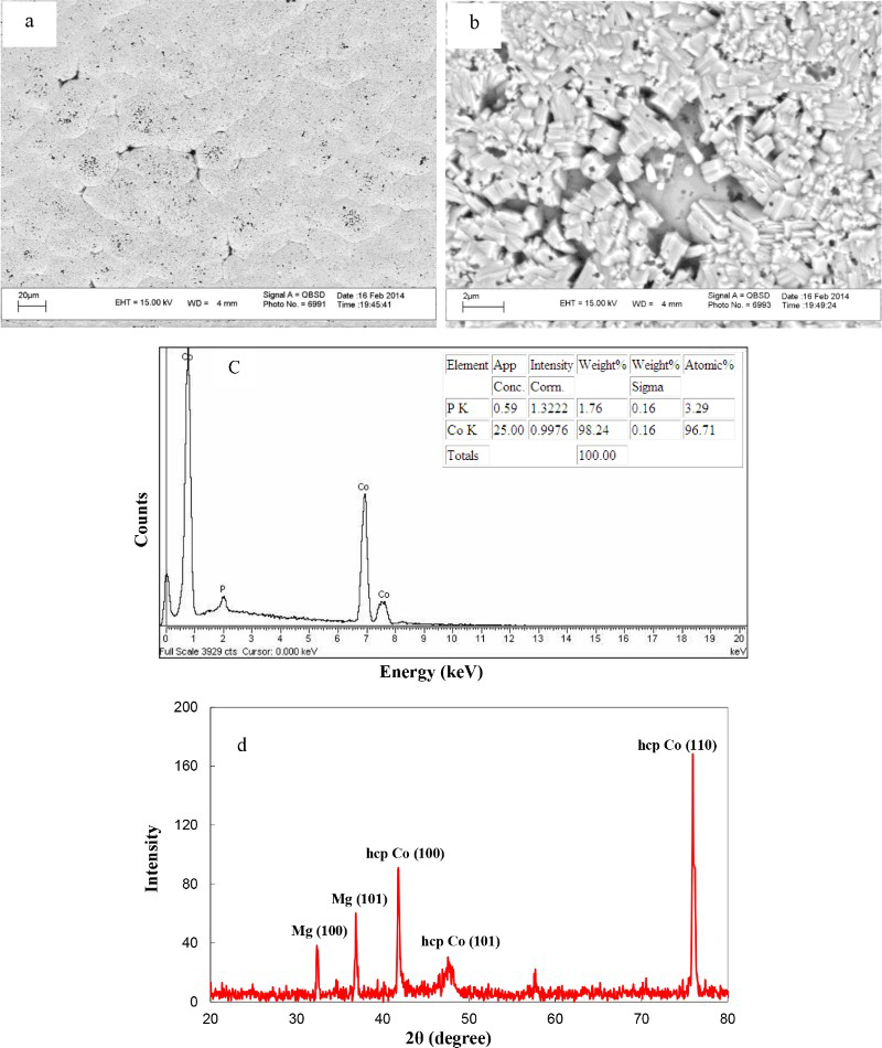
Surface morphology (a 1000 × ; b 15 000 × ), spot EDX analysis (c) and XRD pattern (d) of Co–P coating
Corrosion protection performance
OCP measurements
Corrosion behaviour of the bare alloy and the sample prepared by 5 h electroless plating was studied by OCP measurement. Figure 6a shows the OCP of the bare alloy after immersion in 3·5 wt-% NaCl as a function of time. At the initial times, the OCP of the alloy sample slightly shifts toward positive direction more probably due to barrier action of corrosion products:
19


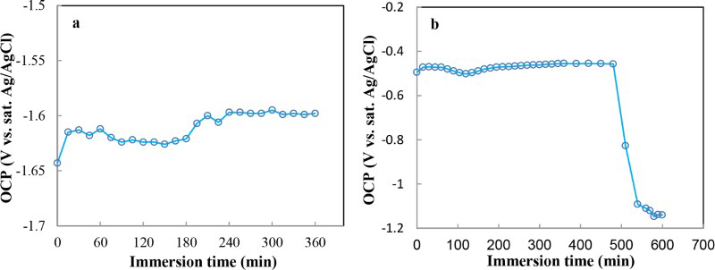
Changes of OCP values as function of immersion time in 3.5 wt-% NaCl solution: a bare alloy; b Co–P coated sample
The Co–P coated sample shows more positive and stable OCP ( − 0·450 V) until its OCP suddenly shifts to more negative values after ∼8 h of the immersion (Fig. 6b). It seems that the corrosive electrolyte gradually diffuses through the intercrystal spaces toward the substrate, but the amount of diffused corrosive solution at the initial immersion times is low. The extent of electrolyte diffusion increases with time, and therefore, the corrosion process takes place at the alloy/coating interface, which produces hydrogen gas. The internal stress due to rapid formation of gas bubbles causes sudden formation of macroscopic crack, which allows the penetration of large amount of corrosive solution. Therefore, OCP of the coated sample shifts toward more negative values due to formation of strong galvanic effect between the coating and active alloy substrate. At the final step of the immersion test, one macroscopic crack was visually observed on the surface as a centre of fast hydrogen gas evolution since the other places of the coating were mainly undamaged even after 8 h immersion in corrosive solution. The same results were observed for at least three other tested samples. The potential difference between the coating and substrate is very large, and any electrolytic contact causes the formation of very strong galvanic effect. Therefore, the applied coating should be pore free and thick enough in order to avoid the above mentioned problems. The applied Co–P coating possesses good corrosion protection performance since it shows more stable OCP during the relatively long immersion time (∼8 h) and no significant galvanic effect due to its compact, pore free and thick structure.
EIS
Corrosion behaviour of the bare and electroless coated (prepared by 5 h) alloy samples were also investigated by EIS method. Nyquist and phase bode plots of the bare alloy after 1 h immersion in the 3·5 wt-% NaCl corrosive solution have been presented in Fig. 7a and b respectively. The Nyquist plot shows a well defined depressed capacitive semicircle at the high frequencies followed by a scattered inductive loop at the low frequencies. The high frequency capacitive loop can be related with the parallel combination of double layer capacitance (at the metal/solution interface) and charge transfer resistance (which is related with corrosion rate),19,21 while the inductive loop at the low frequencies may be related to the partially protective oxide film on the alloy surface and can be explained according to the theory proposed by Cao.
22
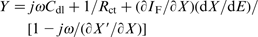
The surface coverage of the natural oxide film (θ) can be regarded as state variable (X) besides the potential (E) affecting the impedance response. Under the above mentioned condition, the faradic and non-faradic admittance of the electrode/electrolyte interface can be expressed as follows:21,22
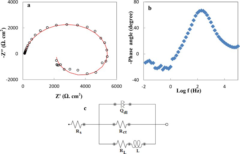
Nyquist (a) and phase bode (b) plots of AZ31 bare alloy after 1 h immersion in 3.5 wt-% NaCl solution and related equivalent circuit (c)
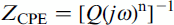
A proper equivalent circuit has been considered based on the above mentioned discussions for data fitting in this case (Fig. 7c). In this model, Rs and Rct describe the solution and charge transfer resistances respectively. Constant phase element (CPE) has been inserted to model the imperfect behaviour of the double layer capacitance due to surface heterogeneity and roughness. The impedance of a CPE element can be given as follows:
23
Impedance parameters for bare and Co–P coated alloy samples in 3.5 wt-% NaCl
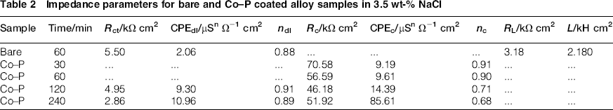
The impedance response of the Co–P coated samples after different immersion times in the 3·5 wt-% NaCl solution is also presented in Fig. 8. The Nyquist plots after 30 and 60 min immersion obviously show one capacitive loop, and therefore, a simple equivalent circuit consisting of a solution resistance (Rs), in series with a parallel combination of a charge transfer resistance (Rct), and a CPE element can be used for data fitting (Fig. 9a). After 2 and 4 h immersion, the Nyquist plots contain an additional small capacitive loop at highest frequencies more probably due to gradual penetration of the corrosive electrolyte toward the alloy substrate. The existence of two capacitive time constants can be more easily observed by the related phase bode plots (Fig. 8b). Therefore, a different equivalent circuit consisting of two capacitive time constants was used for experimental data fitting (Fig. 9b). In this model, Rct and CPEdl describe the charge transfer resistance and double layer capacitance at the alloy/coating interface respectively, while Rc and CPEc elements have been inserted to model the coating resistance and capacitance respectively. All quantitative impedance parameters are given in Table 2. As it is clear, the coating shows much higher impedance value than the bare alloy at all immersion times, indicating significant corrosion resistance improvement after electroless Co–P plating. The coating resistance (Rc) decreases as the immersion time increases more probably due to gradual diffusion of the corrosive solution to the active magnesium alloy surface. However, the coating resistance slightly increases after 4 h immersion, which may be related with filling of the electrolyte transport pathways with corrosion products. Moreover, the values of CPEc increase with the immersion time, which is related with water penetration to the coating since the dielectric constant of the water is very high.
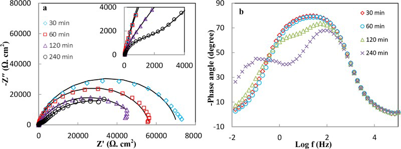
Nyquist (a) and phase bode (b) plots of Co–P coated alloy sample after different times immersion in 3.5 wt-% NaCl solution
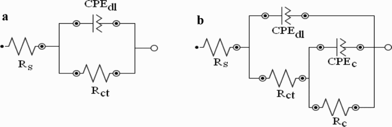
Suitable equivalent circuit for data fitting of Co–P impedance response: a 30 and 60 min immersion; b 60 and 120 min immersion
Conclusion
The main purpose of this study is the corrosion resistance enhancement of AZ31 magnesium alloy by application of electroless Co–P coating. Traditional HF pretreatment was replaced with CLP conversion coating for application of final Co–P electroless coating. The porous nature of the conversion layer was shown by SEM images. SEM and EDX studies showed that the cobalt nucleation centres can be formed around the pores of conversion film at initial immersion times in the electroless bath. Then, the cobalt nucleation centres are grown with time to form cobalt clusters and final electroless coating. Formation of compact, low phosphorous and crystalline electroless Co–P coating on the AZ31 alloy was confirmed by SEM, EDX and XRD analysis. There were no obvious pores or cracks on the coating matrix or substrate/coating interface. Electroless coated sample (obtained by 5 h plating) showed very noble potential than did the bare alloy in the 3·5 wt-% NaCl solution, indicating its good corrosion protection performance. However, the OCP of the coated samples was suddenly shifted to more negative values after ∼8 h of immersion due to formation of macroscopic crack and penetration of the corrosive solution toward the active magnesium alloy substrate. EIS test results showed that the impedance response of the alloy surface significantly increases after electroless Co–P coating application.