
Abstract
Pack chromising treatment is an environmentally friendly alternative to hard chromium to form wear and corrosion resistant surface layers. In this work, samples of AISI 1060 steel were pack chromised for 6 and 9 h at 1000 and 1050°C using different activator concentrations. Wear tests were performed in dry conditions and corrosion tests in natural sea water for the pack chromised samples and hard chromium. Pack chromising yielded the formation of layers with high chromium concentrations, high hardness and wear resistance. Increasing activator concentration causes no significant change on the morphology and thickness of the layers. The layers produced at 1050°C yielded only a (Cr,Fe)2N1−x phase, and those obtained at 1000°C are composed of a carbide mixture with (Cr,Fe)2N1−x. The sample treated at 1050°C for 9 h resulted in an optimum condition by means of better wear resistance and corrosion properties, which were close to that exhibited by the hard chrome, indicating that pack chromising is a promising alternative.
Keywords
Introduction
Surface coatings are one of the most versatile ways to improve the performance of components with respect to wear and/or corrosion. Historically, the most frequently used industrial coating for this purpose is the electrolytically formed hard chrome.1 – 4 However, the electrolytic deposition of the hard chrome coating involves the presence of hexavalent chromium, which is highly carcinogenic and has resulted in increasing limitations of its use. Because of this, several alternative chromising processes have been developed, such as solid (pack) chromising5 – 7 in bath of molten salt8 and vacuum.9 The coating is obtained by diffusion of atoms of chromium into the substrate, which produces a chromium rich layer. The chromising of steel and ferrous alloys produces a surface layer composed mainly of Cr, Fe and C, which significantly increase the hardness, wear and corrosion resistance of the substrate.7, 10
The powder process (pack) is an inexpensive and relatively easy way to obtain chromising coatings with the possibility of processing pieces with different geometries.9 The process involves placing the substrate in a powder mixture containing a source of chromium (pure Cr or Fe–Cr), an inert element (usually Al2O3) and an activator. The package containing the mixture and the sample is heated to 1000–1300°C for up to 12 h to form the coating.7
The objective of this study is to evaluate the influence of pack chromising parameters (temperature, time and activator concentration) on AISI 1060 steel, to study the morphology and composition of the produced layers and to examine its wear and corrosion resistance. These properties are compared with those obtained for a hard electrolyte chromium coating.
Materials and methods
Initially, samples with 20×20×5 mm of AISI 1060 steel were cut and ground using 600 mesh sandpaper. The chemical composition of the steel was Fe–0·57C–0·78Mn–0·036P–0·024S–0·21Si–0·046Ni–0·034Cr–0·003Mo (wt-%). The steel was then cleaned and pack chromised in steel crucibles for 6 and 9 h at the temperatures of 1000 and 1050°C. The composition of the powder was 25% of pure Cr (>150 mesh), 69%Al2O3 and 6 and 12%NH4Cl.
The hard chromium coating was obtained using the traditional electrolytic process, which was performed by a company specialised in these types of treatments using an AISI 1045 steel plate. A layer thickness of 0·7 mm was obtained after grinding. All the studied samples were subjected to analysis by optical and electron microscopy, microhardness measurements, X-ray diffraction, wear and corrosion testing.
Measurements of Vickers microhardness were made on a digital Buehler equipment with a load of 50 gf and an application time of 10 s. The X-ray diffraction patterns were obtained on the surface of the samples in a Geigerflex Rigaku equipment with a scanning angle from 20 to 100°. The tests were performed using copper radiation and continuous scanning with a speed of 2° min−1.
Optical microscopy analyses were performed on a Zeiss microscope using the interference contrast technique on samples etched with 1% nital. Electron microscopy was performed using a scanning electron microscope (LEO 440 model) with a tungsten filament. Analysis by energy dispersive spectroscopy was conducted to obtain the chemical composition of the layers.
Wear tests were performed on a microwear machine with a fixed ball configuration without the use of an abrasive. The diameter of the ball was 25·4 mm with a rotational speed of 350 rev min−1 and load of 1350 g (13·50 N). Consecutive wear scars with test times of 10, 15, 20 and 30 min were produced to obtain the volume loss curve. The removed volume of each wear crater and its depth h were calculated according to the literature.11
The electrochemical cell used to obtain the potentiodynamic polarisation curves utilised a saturated calomel reference electrode and a platinum auxiliary electrode. The electrolyte employed was natural sea water (pH 8·07), which was collected from a Brazilian beach. For monitoring the potential and current, an Autolab model PGSTAT-302 potentiostate was used. The polarisation curves of the samples were obtained with a scanning speed of 1 mV s−1 from −0·8 to 1·125 V.
Results and discussion
The average thickness of the formed layers for each condition of treatment was measured directly from the optical micrographs of the cross-section. The variations in thickness of the layers versus treatment time for the temperatures of 1000 and 1050°C and the concentrations of activator of 6 and 12% are shown in Fig. 1.
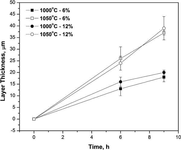
Layer thickness versus treatment time for temperatures and activator concentrations studied
It is observed that the increase in activator concentration from 6 to 12% did not generate significant changes in the thickness and morphology of the obtained layers. Therefore, the lowest concentration of activator (6%) was chosen for further study.
Figure 2 shows optical micrographs of cross-sections of the chromised samples for the activator (NH4Cl) concentration of 6% and temperatures of 1000 and 1050°C for treatment times of 6 and 9 h. Thicker layers (Fig. 2b) with increasing treatment times and temperatures are observed. All the formed layers are continuous and with low porosity, showing the pearlite–ferrite matrix beneath.
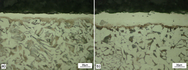
Optical micrographs of cross-sections of pack chromised samples: a 6 h–1000°C; b 9 h–1050°C
Punctual energy dispersive spectroscopy analysis on the cross-section of the samples chomised at 1050°C indicated an average chromium concentration of 29wt-% for those layers. Baggio-Scheid et al.12 found a layer with 20 wt-% of chromium after chromising at 1200°C using a similar mixture.
For all pack chromising conditions, the microhardness values near the surface were in the range of 1400–1800 HV. The hard chromium coating yielded a surface hardness of ∼950 HV, which is almost half of the value obtained for pack chromised samples.
For the samples treated at 1000°C, there is a sharp drop in microhardness as the substrate (AISI 1060 steel) is approached, which was ∼200 HV. The chromisation treatment at 1050°C, due to the presence of an intermediate layer (Fig. 2b), exhibited a level close to 700 HV, which then decreases to the hardness level of the substrate.
Figure 3 shows the X-ray patterns of the chromised samples: for 6 h at 1000°C (Fig. 3a) and for 9 h at 1050°C (Fig. 3b), together with the positions of all Bragg reflections for the identified phases. For the samples treated at 1000°C, there is the major presence of (Cr,Fe)2N1−x intermetallic type and in smaller quantities (Cr,Fe)7C3 and Fe2C, like those indicated by the intensity of diffraction peaks. Al2O3 peaks were also found as a residue from the filler material used on the pack mixture.
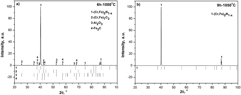
X-ray patterns of pack chromised samples: a for 6 h at 1000°C; b for 9 h at 1050°C
The treatment at 1050°C resulted in the formation of (Cr,Fe)2N1−x intermetallic type only. This suggests that the temperature in pack chromising is an important parameter controlling the formation of nitrogen and/or carbon compounds. The formation of (Cr,Fe)2N1−x is possible due to the nitriding reaction of chromium and iron after the decomposition of NH4Cl, which is added to the chromising mixture as an activator.3 The ferrite matrix is not revealed in all analyses due to the reduced penetration of the X-rays, which is in agreement with the study by Arai and Moriyama.8
It is worth to note that for both diffraction patterns in Fig. 3, the most intense peaks are the (002) and (004) reflections of the chromium–iron nitride phase respectively. Other research papers13, 14 have already shown that (Cr,Fe)2N1−x is the primary phase of the outermost surface region of the chromised samples. This observation explains the attainment of intense reflections for the chromium–iron nitride compound.
Increasing chromising temperature and time lead to the weakening (6 h–1050°C and 9 h–1000°C) and even the extinction (9 h–1050°C) of the reflections related to (Cr,Fe)2N1−x, (Cr,Fe)7C3 and Fe2C, remaining only the (002) and (004) of the chromium–iron nitride (Fig. 3b). This effect can be associated to the fact that hard coatings are often subjected to the development of a strong texture.15
Figure 4 provides the results of volumetric wear loss versus running distance for all chromised samples using 6% of the activator at 1000 and 1050°C after 6 and 9 h of treatment.
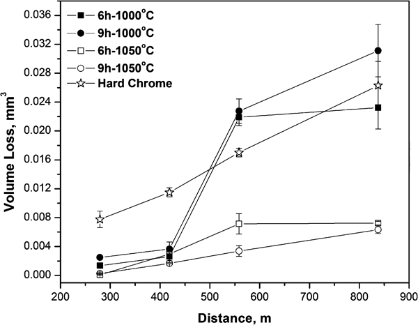
Wear volume loss curves of pack chromised samples and hard chrome
For the samples treated at 1050°C, a low wear volume was observed, indicating the high wear resistance of these coatings. Samples treated at 1000°C showed similar behaviour up to the distance of 419 m. Beyond this distance, the wear process became accelerated due to the perforation of the chromium rich layer, which started the wear process on the substrate.
Table 1 is a compilation of the wear depths h compared with the layer thickness e of all chromised layers. The wear depth of the hard chrome layer and the steel substrate (AISI 1060), which yielded a wear depth of about seven times greater than the chromium layer, which was obtained after treatment at 1000°C for 9 h, and 16 times greater than that obtained after treatment at 1050°C for 9 h, is also shown. Hard chrome yielded a wear depth two times larger than that obtained for pack chromising at 1050°C for 9 h.
Scar depth h after 30 min of wear testing and chromising layer thickness e
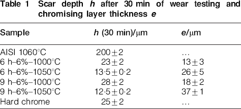
Comparing the shape of the wear curve (Fig. 4) with Table 1, it is verified that in the case of the samples treated at 1000°C, wear occurred due to the perforation of the layer. Even with the perforation of the layers, these samples supported the applied load, resulting in low wear when compared to the base AISI 1060 steel. Those samples subjected to pack chromising at 1050°C did not undergo perforation of the layer, resulting in greater wear resistance.
These differences in the tribological behaviour of chromised samples may be mainly attributed to the differences in layer thickness produced by the pack chromising process.
The hard electrolyte chromium coating yielded the greatest wear volume up to the distance of 419 m among all of the samples tested. Beyond this distance, its wear was close to that observed for samples treated at 1000°C.
Examinations inside the wear craters obtained on the chromised samples, after 838 m, indicated that the main active wear mechanism was a grooving process (two-body abrasion) due to the presence of parallel ridges inside of the scars.
In Fig. 5, the potentiodynamic polarisation curves obtained in natural sea water for the pack chromised samples, the AISI 1060 substrate and the hard chrome are compared. After corrosion testing, the pack chromised layers and the hard chrome provided the coated material with a superior corrosion resistance when compared with the AISI 1060 substrate.
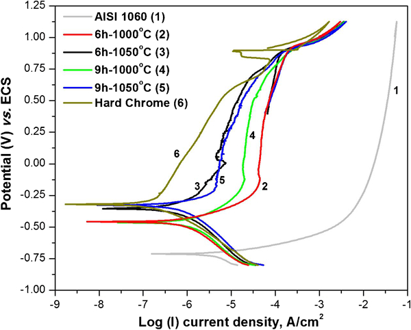
Potentiodynamic polarisation curves of pack chromised samples, hard chrome and AISI 1060 steel substrate
The electrochemical reactions that occur on the surfaces of the coated samples are far less destructive than those which occurred on the unprotected carbon steel substrate. This is shown by the potentiodynamic polarisation curves of the four chromium coatings and the hard chrome that exhibit a passivity region in which the rate of corrosion reaction is low. Moreover, the corrosion currents are shifted to the left, which indicates minor current values relative to the substrate.
Among the pack chromising conditions, the ones treated at 1050°C resulted in better corrosion behaviour. The increase in corrosion resistance for the samples treated at 1050°C can be attributed to the fact that these samples are externally composed mainly of (Cr,Fe)2N1−x, as shown by the X-ray diffraction analysis (Fig. 3b). The polarisation curves also show that the protection against corrosion increases with the pack chromising time and temperature, which is the most significant parameter.
It is well known that the higher Cr concentration that the coating possesses, the better corrosion resistance that the coating exhibits.4 This fact suggests that at 1050°C, the Cr concentration on the layer is higher, which results in better corrosion protection.
Table 2 shows the electrochemical parameters, such as corrosion potential Ecorr, corrosion current Icorr and polarisation resistance Rp, of the tested samples collected from the polarisation curves. Rp is calculated by the quotient V(Ecorr)/I(Icorr), which indicates that if Rp decreases, corrosiveness of the medium increases, and if the electrolyte is the same, this indicates that the sample with lower Rp undergoes greater corrosion.16
Electrochemical parameters from polarisation curves
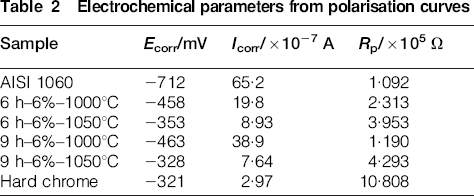
The decreasing order of corrosion resistance of the samples is hard chrome, followed by the sample chomised at 1050°C for 9 h, 1050°C for 6 h, 1000°C for 6 h, 1000°C for 9 h and the substrate which undergoes major corrosion rate.
Conclusion
From the experiments, it can be concluded that pack chromising treatment is an effective way to obtain layers with high chromium concentration, high hardness and good wear and corrosion resistance. An increase in activator concentration from 6 to 12% did not generate significant changes in the thickness and morphology of the produced layers, which were found to increase with treatment temperature and time. The microhardness for all the pack chromised samples was similar and almost 50% higher than the hard chromium.
The samples chromised at 1000°C are composed by a carbide mixture [(Cr,Fe)7C3 and Fe2C] and (Cr,Fe)2N1−x, and the samples obtained at 1050°C composed of only (Cr,Fe)2N1−x. All the pack chromised samples and the hard chrome yielded better wear performance than the AISI 1060 substrate. The samples produced at 1050°C exhibited greater wear resistance under dry sliding conditions.
The protection against corrosion increases with pack treatment time and temperature, with temperature being the most significant factor. All chromium coatings are more corrosion resistant than the AISI 1060 substrate. The sample pack chromised at 1050°C for 9 h yielded a corrosion resistance close to the hard chrome coating, which is a promising condition for replacing the commercial hard chromium coating.
Thus, chromising at 1050°C for 9 h provides an optimum condition in order to obtain higher corrosion and wear resistance.
Footnotes
Acknowledgements
The authors acknowledge CAPES for the scholarships granted to F. A. P. Fernandes and S. C. Heck and the CNPq.