
Abstract
This paper addresses the residual stress in the microarc oxidation (MAO) coating on AZ31 magnesium alloy. The MAO coating was deposited by pulsed direct current (dc) and examined by scanning electron microscopy and X-ray diffraction for its microstructure and composition. The porosity of the coatings was measured by potentiodynamic polarisation tests and found to be in the range of 3–6%. The residual stresses in the MAO coatings prepared at 300, 500, 1000 and 3000 Hz respectively were found to be between −860 and −1272 MPa. Using a high pulse frequency at 3000 Hz can produce a less porous and less stressed MAO coating, a desirable feature in the biomedical applications of MAO coated AZ31. This finding was further verified by establishing a first principle relation between the residual stress and the porosity via Stoney equation, which enables extrapolation of the experimental data measured.
Introduction
Metallic materials such as stainless steels, cobalt based alloys and titanium alloys are commonly used to enhance the supporting capacity of fractured bones because of their strength, ductility and resistance to corrosion.1, 2 Today, many metallic implants are considered as exogenous fixtures that, in the form of plates, screws and pins for repairing serious bone fractures, must be removed in another surgical procedure after the damaged tissue heals.1, 2 The repeated surgeries adversely increase both healthcare costs and infection.
Magnesium is biodegradable and biocompatible and a promising material for temporary implants. Magnesium could replace existing implant materials, facilitate healing, and reduce healthcare costs because of potential waiving of the unnecessary surgeries.1, 3 – 6 However, Mg alloys rapidly degrade in the human body because they are easily corroded in the tissue fluids. Its lifespan usually lasts for 12–18 weeks in body fluids.1 This constraint adversely restricts any practical application of the Mg alloys as suitable implant materials.7 In response to this, coating has been suggested as a method of reducing the corrosion rate.
Microarc oxidation (MAO), an oxidised coating technique on the Mg substrate, enables a corrosion resistant ceramic layer on the surface of magnesium alloys.8 – 12 However, the detrimental residual stresses developed in the MAO coatings could reduce the corrosion resistibility of these coated components.13, 14 Understanding the causes and then reducing the residual stress during the MAO process could be a key to improving the anticorrosion property of the MAO coatings.
The control parameters in the MAO process, such as the pulse frequency of the direct current (dc) source, the compositions of the electrolyte, treatment time and applied voltage, collectively determine the quality of MAO coatings.11, 15 – 17 The effects of the pulse frequency on the morphology, phase composition and anticorrosion performance of the MAO coatings on the magnesium alloys have been studied.15, 18, 19 It is known that residual stress appears during MAO coating, and the adjustment in the pulse frequency will change the residual stress. However, the influence of pulse frequency on the residual stress is not well understood. This paper presents the effect of the pulse frequency (under a constant pulse/time ratio) on the residual stress in MAO treated AZ31 alloys and characterises the coatings in terms of their phase composition, microstructure and porosity.
Experimental
Microarc oxidation coating preparation
The substrate for the MAO coating deposition was made of AZ31 specimen 20×10×1 mm in size. AZ31 has the following chemical compositions: 2·5–3·5 wt-%Al, 0·7–1·3 wt-%Zn, 0·2–1·0 wt-%Mn, 0·05 wt-%Si, 0·01 wt-%Cu and Mg balance. A few substrates were successively ground on various grade SiC papers to a roughness Ra of ∼1·6 μm, ultrasonically cleaned and dried. The MAO coating was processed in the MAO20 equipment (Chengdu PULSETECH Electrical Co., China), which has an adjustable dc pulse source up to 50 kW and comprises a stainless steel container with a sample holder, stirring and cooling system. The AZ31 substrate and the walls of the stainless steel container were used as anode and cathode respectively. An electrolyte prepared from 10 g L−1 Na3PO4 solution in distilled water was kept at room temperature during the entire treatment procedure. The coatings were obtained under a constantly applied voltage of 325 V for 5 min at four pulse frequencies of 300, 500, 1000 and 3000 Hz respectively. The pulse/time ratio of all the pulse frequencies is set to be 3∶7 (i.e. 1∶2·333, 0·6∶1·4, 0·3∶0·7 and 0·1∶0·2333 ms respectively).
Coating characterisations
Scanning electron microscopy (Netherlands Quanta200) was used to examine the surface morphologies of the MAO coated specimens, while X-ray diffraction (XRD) (X'Pert PRO MRD, PANalytical B. V., The Netherlands; Cu Ka radiation, 45 kV and 40 mA) was used to determine the coating composition.
Potentiodynamic polarisation tests
The porosity of the MAO coating was assessed by potentiodynamic polarisation tests, in which a computer controlled potentiostat/frequency response analyser (Corrosion Cell Kit, Gamry Instruments, Inc.) was used. The tests were conducted in a typical three-electrode cell in which the coated sample served as a working electrode, a saturated calomel electrode (SCE) as the reference electrode and a graphite rod as the counter electrode. All the tests were carried out in a 1000 mL simulated body fluid (SBF) with ionic concentrations per the compositions: Na+, 142·0; K+, 5·0; Ca2+, 2·5; Mg2+, 1·5; Cl−, 147·8;
 , 1·0;
 , 4·2; and
 , 0·5 mmol L−1.20 Potentiodynamic polarisation tests were performed after 10 min of exposure at open circuit potential at a scanning rate of 3 mV s−1, starting at −2·1 to −0·5 V after exposing the specimens with a surface area of 4·18 cm2 to the SBF for 0·5 h.
Residual stress measurement
The residual stress in the MAO coating was measured by the XRD sin2 ψ method21 using the diffracted peak (220) at 2θ = 62·306° (which corresponds to the MgO phase, Fig. 1). This comparatively high angle diffraction peak (220) was chosen to reduce the measurement error and to ensure high sensitivity to the strain.14, 22 The measurements were carried out at five different values of ψ (0, 7·5, 15, 22·5 and 30°) in the 2θ range from 61·75 to 63·00° with a step size of 0·0125°.
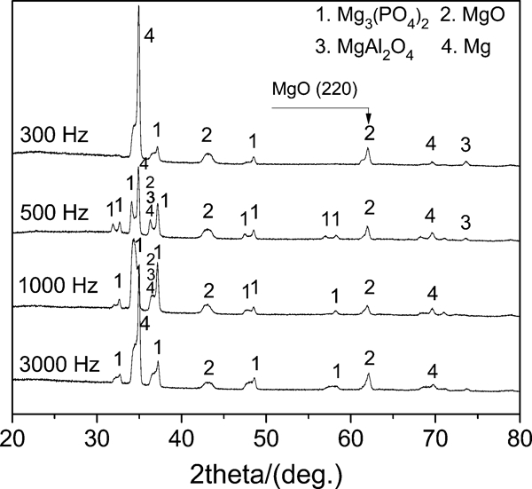
X-ray diffraction patterns for MAO coated AZ31 alloy at different frequencies
The residual stress developed in MAO coatings on the AZ31 substrate was calculated by23
The change in the lattice spacing d at different ψ values results in a corresponding peak shift. The measured 2θ can be plotted against sin2 ψ. Therefore, the residual stress in the coating can be determined by the slope of the linear regression in the 2θ versus sin2 ψ plot.
Results and discussion
Surface phase analyses
The XRD patterns of the coatings in each of the four samples, as obtained at different pulse frequencies shown in Fig. 1, suggest that the processing frequency has little influence on the phase composition, and that the coating in each sample has the same compositions: Mg, MgO, MgAl2O4 and Mg3(PO4)2. The Mg phase, attributed to the AZ31 substrate, exhibits a different extent of peak in the XRD pattern from sample to sample, while the MgO phase is barely influenced by the pulsed frequency of the dc source. The MgAl2O4 phase has a low intensity but can still be detected with peaks at 2θ = 74·133° for the 300 and 500 Hz samples, and becomes undetectable for both 1000 and 3000 Hz samples because (1) a very low amount of Al exists in AZ31, and (2) the discharge at 300 Hz, which is comparatively continuous and prolonged, results in a relatively high temperature in the discharge channels, propitious to the formation of this low symmetry oxide. At higher frequencies, a large amount of Mg3(PO4)2 was observed, suggesting that the electrolyte ions participated in the growth process of the coating.25
Surface morphology
The effect of different pulse frequencies for MAO deposition on the surface morphology of the resultant MAO coatings is illustrated by the SEM images in Fig. 2a–d. Micropores and cracks were observed on the coating surface for all the four frequencies tested, albeit different porosities at each frequency. During the MAO deposition, the pores and cracks served as the microarc discharging channels through which the oxide leaves the surface and then experiences intensive oxygen evolution, which partly resulted in the porous structure of ceramic coatings. The number of pores on the surfaces of the specimen coated at 300, 500 and 1000 Hz is similar (Fig. 2a–c), while for the 3000 Hz sample, the number seems to be the largest. The average pore size and the average crack size decrease with the increase in pulse frequency.
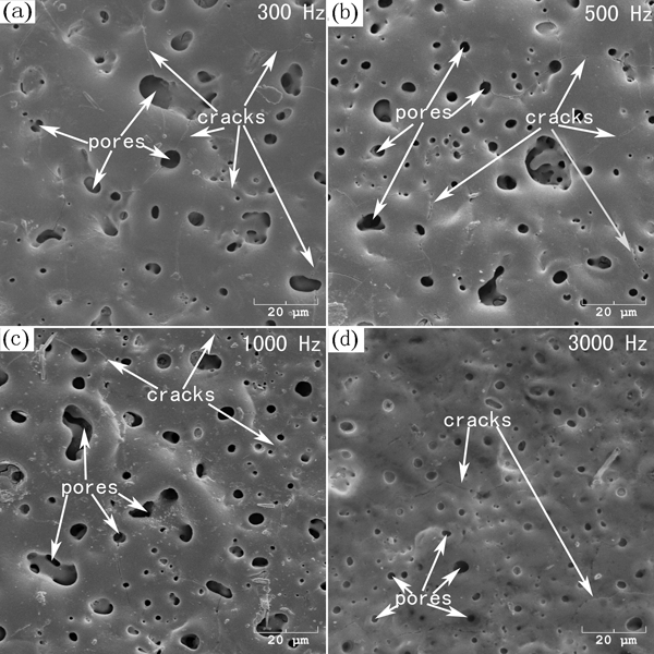
Surface morphology of MAO coatings on AZ31 alloy formed by pulse frequency at a 300 Hz, b 500 Hz, c 1000 Hz and d 3000 Hz
The differences in the extents of microcracks and micropores in the four coatings can be attributed to the intensity of energy used in the MAO process.26 Although all the four pulse frequencies were operated at the same pulse/time ratio, the 3000 Hz case only has a discrete pulse on time of 0·1 ms, as opposed to 0·3 ms (1000 Hz), 0·6 ms (500 Hz) or 1 ms (300 Hz). This indicates that the pulse frequency at 3000 Hz delivers the least intensity of energy (among the four cases tested) and thus resulted in a coating that has relatively smaller sized micropores and microcracks. At 300 Hz, larger pores are produced (Fig. 2a) because of the relatively prolonged pulse on time (1 ms), which is much longer than the lifetime of the spark and thus results in continuous breakdown of longer period. In addition, at 300 Hz, the continuous discharge during the pulse on time leads to higher temperature in the coating layer, and the heavier quenching effects induce microcracks.26
Porosity measurements of MAO coatings
The vulnerability of a coating against an aggressive environment is directly in connection with the per cent of the pores in the MAO coating;27,
28 therefore, porosity measurement for the coating is necessary. The most often used method for measuring the porosity in the coating is equation (2) introduced by Tato and Landolt29
Figure 3 compares the potentiodynamic polarisation curves of AZ31 Mg alloy and the specimens treated by the MAO process at various pulse frequencies. The corrosion potential (Ecorr), corrosion current density (Icorr) and anodic/cathodic Tafel constants (βa and βc) were extracted directly from the potentiodynamic polarisation curves by the Tafel fit method using the Gamry Echem Analyst software. The polarisation resistance (Rp) can then be obtained per the Stern–Geary equation30
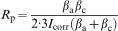
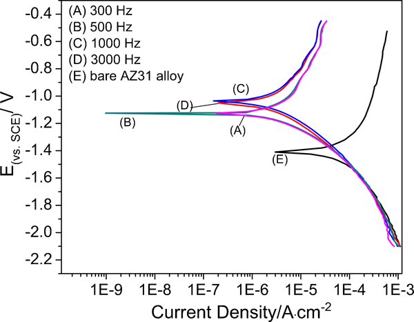
Tafel curves of MAO coated samples and bare AZ31 alloy after immersion in SBF for 0·5 h
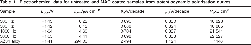
Electrochemical data for untreated and MAO coated samples from potentiodynamic polarisation curves
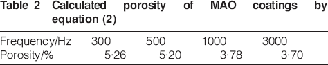
Using the data in Table 1, the coating porosity (F) was calculated per equation (2), and the results are listed in Table 2. The results show that the porosity (%) proportionally increases with the pulse frequency. These results are in the range of 3·70–5·26%, similar to Cai's report.31 It was found that the 3000 Hz sample has the lowest porosity of 3·7%, meaning that the densest coating in this study was produced at 3000 Hz.
Calculated porosity of MAO coatings by equation (2)
Residual stresses
Table 3 lists the calculated residual stresses in the MAO coatings. The stresses are compressive and their magnitudes decrease with the pulse frequency.
Residual stresses in MAO coatings deposited on AZ31 substrates at different pulse frequencies

Because the porosity changes the equivalent Young's modulus and Poisson's ratio of the thin film the residual stress in the thin film is accordingly amended. Stoney equation is used to relate the thin film stress σf to the mechanical properties of the film and the substrate32


Conclusion
This paper studied the microstructure and residual stresses in MAO coatings that were deposited onto AZ31 magnesium alloy at various dc pulse frequencies for developing new corrosion resistant biomaterials. The compressive residual stresses developed in the MAO coating during the deposition process were measured by the XRD sin2 ψ method. The results show that the porosity and magnitude of the residual stresses in the MAO coating are smaller when a higher pulse frequency was used for the deposition. This trend may be attributed to the intensity of energy supplied in the deposition process. The relation between the residual stress and the porosity was successfully established via the use of Stoney equation, which may be suitable to extrapolate the influence of the pulse frequency on the residual stresses in the MAO coating.
Footnotes
Acknowledgements
Y. H. Gu was supported by the UAF Graduate School Fellowship for the related research initiated by Dr. J. Zhang.