
Abstract
Hot dip aluminised coatings with pure Al, Al–3Si and Al–7Si melts had been produced on 9Cr–1Mo steels and subsequently heat treated at 900°C for 5 h under oxidising conditions to generate alumina films over Fe–Al diffused case. The characterisation of these samples by X-ray diffraction and SEM-EDX techniques indicated reduction in the post-heat treated aluminide case depth with increasing Si concentration. Further, it was observed that after oxidation heat treatment, pure Al coated samples indicated γ-Al2O3 and θ-Al2O3, while Al–7Si coated samples revealed transformation of metastable θ-Al2O3 phase to stable α-Al2O3 phase. The present paper describes change in morphology of oxide after thermal oxidation from γ to θ and θ to α as a function of the Si content of Al melt in hot dip aluminised 9Cr–1Mo steels. The effect of Si on the diffused aluminide case depth is also discussed.
Introduction
The Indian test blanket module (TBM) known as lead lithium ceramic breeder design for fusion reactor includes a solid as well as a liquid breeder concept for generation of tritium fuel as well as extraction of heat to generate energy. A few of the key issues to be addressed in the lead lithium ceramic breeder TBM design are protection of structural material (i.e. reduced activation ferritic–martensitic steels) against corrosion from flowing liquid breeder (Pb–15·7Li) at 325–480°C, prevention of tritum permeation into steel from Pb–17Li and electrical insulation for reduction of drag by magneto hydrodynamic effect.1 Al2O3 has been considered candidate coating for TBM applications. As such, though Al2O3 is found to be resistant to Pb–15·7Li attack, the large difference in coefficient of thermal expansion as compared to structural material leads to cracks and spalling,2 and hence, Al2O3 alone cannot be coated on reduced activation ferritic–martensitic steels. Aluminised coatings, which generate intermetallic iron aluminides with a top alumina ceramic insulating layer, have been considered candidate coatings for TBM applications.3 Out of the work related to various aluminising techniques as reported by Shikama et al.3 for TBM applications, hot dip aluminised (HDA) technique has been found acceptable for TBM geometries owing to the ease of processing complex geometries.4 Since thinner Al coatings are desired from reduced activation perspective, Si alloying of Al melt is important. As reported by Bouche et al.,5 the effect of Si as alloying element in Al can reduce the liquidous temperature and improve the fluidity of the liquid aluminium bath, thus reducing the overall coating thickness. Another reason to add Si in Al is the reduction of Fe2Al5 (η) intermetallic phase forming at coating/substrate interface. It has been known that η phase is a brittle intermetallic phase forming beside substrate. Since η phase has ∼30% vacancies in the c axis, the growth of this phase in pure Al melt is very fast with a tongue- or finger-like morphology.6 This η phase has to be transformed to lower Al rich phases, which is possible by longer time scales of heat treatment. As reported by Awan and Hasan7 and Springer et al. 8 for HDA, Si occupies the c axis position of the Fe2Al5 (η) lattice and thereby reduces the vacancies and the rate of η layer growth.7 While the role of Si in as coated aluminised conditions has been extensively reported,6, 8 its effect on the stability of alumina polymorph on aluminised 9Cr steels is not specifically reported. A diffusion aluminide coating with FeAl phase on 9Cr steels and a top insulating α-Al2O3 layer was reported by Glasbrenner and Konys9 for TBM applications. However, large Kirkendall porosities were generated, which were then suppressed by hot isostatic pressing.9 It is therefore important to generate α-Al2O3 without formation of large kirkendall porosities. The effect of Si on the stability of thermally grown alumina phases over aluminised 9Cr steels is scarcely reported. Thus, the study of such alloying on the coating microstructure with specific emphasis on the morphology of oxide after oxidation heat treatment has been attempted here. The present paper discusses the effect of Si addition on the transformation of alumina from γ to θ and θ to α phase. Its effect on the microstructure of the diffused aluminide coating is also discussed in subsequent sections.
Experimental
9Cr–1Mo steels conforming to ASTM A 387 Gr91 class 2 as per composition of Fe–0·09C–9·30Cr–0·88Mo–0·45Mn–0·019P–0·003S–0·20Si–0·20V–0·088Nb (wt-%) were cut to 35×10×2 mm size and polished as per ASTM E3-01 up to 600 grit size. The polished samples were ultrasonically cleaned with acetone and subsequently pickled using 10%H2SO4. After pickling, the samples were rinsed in distilled water and then subjected to pretreatment of K2ZrF6 aqueous fluxing as specified in IS:8508-2006.10 The fluxed samples were then subjected to HDA. Molten bath of pure Al, Al–3Si and Al–7Si by weight was prepared in a graphite crucible placed in a top loading resistance type box furnace and held at 715±5°C. The fluxed samples were slowly immersed in Al/Al–Si melts for 30 s and subsequently withdrawn. The resultant coated samples were then cleaned and subjected to oxidation heat treatment in a muffle furnace at 900°C for 5 h under static air environment. The temperatures were measured with K type thermocouple placed beside the samples with ±10°C variation. The sample processing history is as listed in Table 1.
Sample identification and processing conditions*
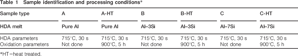
HT = heat treated.
Characterisation
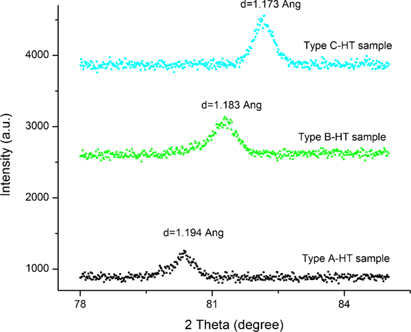
The HDA 9Cr–1Mo steel samples (as coated and heat treated) were characterised using X-ray diffraction (XRD), SEM and EDX techniques for compositional and phase analysis. X-ray diffraction studies were conducted using PanAnalytical make XRD system (model: X'Pert PRO) with Cu Kα radiation (λ = 1·5406 Å and 2θ = 20–90°) in Bragg–Brentano geometry. The XRD spectra as obtained for heat treated have been plotted in Fig. 2 , and a table of the XRD data for alumina phases has been given in Table 2. The oxidised surface morphology and the metallographic cross-section of the aluminised samples were studied using a LEO Corporation make scanning electron microscope (model s440i). Al diffusion profiling by spot elemental analysis was done using EDX technique equipped with the SEM.
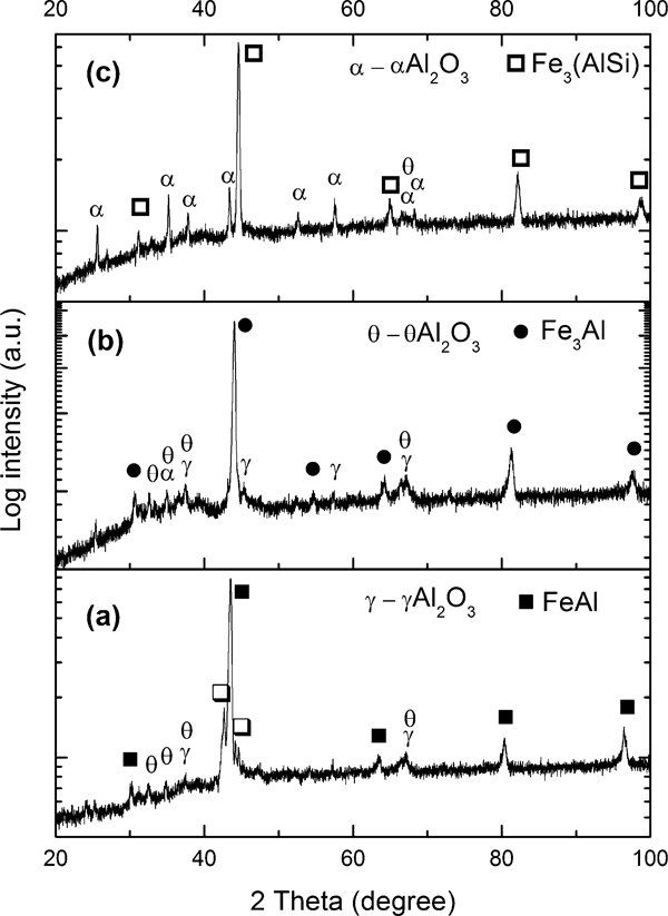
X-ray diffraction plots of HDA and oxidation heat treated 9Cr–1Mo steel samples with a A-HT, b B-HT and c C-HT type samples
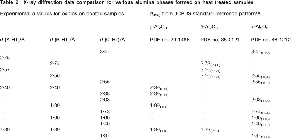
X-ray diffraction data comparison for various alumina phases formed on heat treated samples
The cross-section micrographs of the as coated samples of type A, B and C are given in Fig. 1. There is only a slight reduction in the coating thickness with increasing Si content, i.e. the pure Al coated sample (type A) had ∼30 μm coating thickness, while the Al–7Si coated samples (type C) had ∼25 μm thickness. This could be possibly because the pure Al used for melting was a commercially pure alloy, which might comprise of Si up to 0·25 wt-%. It was observed that the Fe2Al5 (η) and FeAl3 (θ ) phase forming at the interface in type A samples has converted into a homogenous layer of Al8Fe2Si (τ5) in type C samples.
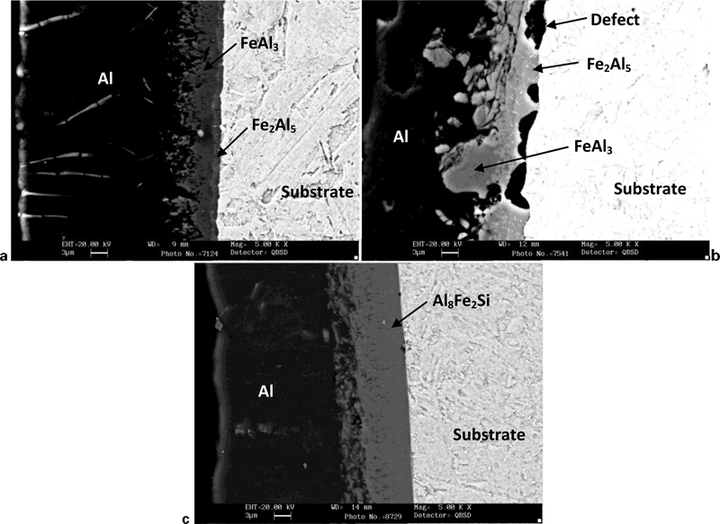
Backscattered SEM image of as coated a pure Al coated, b Al–3Si coated and c Al–7Si coated 9Cr–1Mo steel samples
After an oxidation heat treatment at 900°C for 5 h in muffle furnace under static air, the XRD results (Fig. 2) of A-HT type samples showed peaks of predominantly existing phases, namely, FeAl (JCPDS file no. 33-0020] with some peaks of Fe2Al5 (JCPDS file no. 47-1435). Type B-HT samples showed Fe3Al (JCPDS file no. 45-1203) and type C-HT samples revealed Fe3(AlSi) phase (JCPDS file no. 45-1204) as main phases of the aluminide case. Apart from this, various oxide peaks corresponding to alumina polymorphs were observed and listed in Table 2. The metastable γ-Al2O3 phase (JCPDS file no. 29-1486) and θ-Al2O3 phase (JCPDS file no. 35-0121) were visible in type A-HT and B-HT samples, while Al–7Si (type C-HT) showed peaks of stable α-Al2O3 phase (JCPDS file no. 46-1212) as shown in Fig. 2 and Table 2. The SEM surface observation on the morphology of oxides as indicated in Fig. 3 showed whisker-like morphologies in pure Al aluminised samples (A-HT), which is linked with γ-Al2O3, while plate type morphologies were observed in Al–3Si (B-HT) and Al–7Si aluminised samples (C-HT), which are linked with θ-Al2O3. The surface observation of Al–3Si coated samples (B-HT) showed both whisker and plate type morphologies, indicating the presence of both γ-Al2O3 and θ-Al2O3.
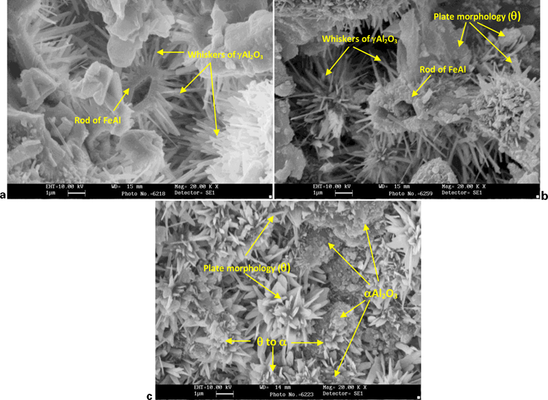
Surface morphology of oxides formed on a pure Al coated (A-HT), b Al–3Si coated (B-HT) and c Al–7Si coated (C-HT) samples with whisker-like, mixed and plate type morphologies respectively: Al2O3 can be observed with equiaxed globular type morphology
Results and discussion
HDA coating
HDA yielded a coating of ∼30 μm in type A samples, while the type C samples with Al–7Si yielded ∼25 μm coating thickness as shown in Fig. 1. The overall coating microstructure can be divided into three zones, i.e. Al coating, intermetallic zone and substrate. The intermetallic zone so formed is mainly composed of FeAl3 and Fe2Al5 in pure Al coatings, while this interface transforms to Fe–Al–Si intermetallics for Al–Si coatings.5, 11 The type A and B samples showed Fe2Al5 interface close to substrate followed by FeAl3 as shown in Fig. 1a and traces of Fe–Al–Si complex phases in type C samples. Sample C showed Al8Fe2Si (τ5) as main constituent phase of the interface zone as confirmed from EDX data and is matched to the composition reported by Cheng and Wang6, 12 for τ5 phase. The presence of Si at the interface reduces the growth of the interface layer and also reduces the overall aluminised coating thickness,7 which might have resulted in a relatively thinner coating for Al–7Si as compared to the pure Al coated samples. As reported by Awan and Hasan7 and Cheng and Wang,12 finger or tongue-like morphology is observed for interface of pure Al coating owing to high growth rate of Fe2Al5 phase. However, it was not observed in the type A coating of this experiment since a commercially pure Al was used as Al melt, which might have some silicon up to 0·25 wt-% as impurity element. Addition of Si in Al melt in 3 and 7 wt-% concentration reduced the coating thickness to a minor extent and also changed the phase composition of the intermetallic interface as well as its morphology.
Surface morphology of Al2O3
After oxidation heat treatment was carried out as indicated in the section on ‘Experimental’, an alumina layer is formed on the surface of the coated sample, while Fe–Al intermetallic layer forms due to high temperature diffusion phenomena. Alumina (Al2O3) exists in various allotropic forms namely, α, γ, θ, κ, etc. as reported in various literature. 13 13,14 Out of the various phases indicated, only α-Al2O3 is a stable phase, which is desired as a protective coating, while the rest of the phases, i.e. γ, θ, κ, etc., are metastable transition phases and are undesired from poor stability point of view.15 It is understood that stable alumina phase forms at temperatures >950°C, while at lower temperatures the metastable transition alumina are generated.14 In this work, the effect of Si alloying in Al coating on the formation of the alumina phase has been discussed below.
The type A-HT samples showed a whisker (needle)-like morphology along with rod-like structures as shown in Fig. 3a (A-HT). These whiskers were identified as γ-Al2O3 by Chang et al.16 for similar work, where the rodlike structures were FeAl on which the γ-Al2O3 whiskers had grown. This was because of Al3+ ions migrating outwards from the centre of the FeAl rod to form whiskers; as a result, the rods can be seen hollow at the centre. Apart from this, some blade and plate type morphologies were also observed, which could be of θ-Al2O3.17 Both of these transition alumina phases are also visible from the XRD data (Fig. 2 and Table 2). It is known that these transition aluminas (γ and θ) grow due to faster outward migration of Al3+ ions, while a stable alumina (α) forms due to faster inward migration of O2− ions. These needle-like structures are a result of such outward migration of Al3+ ions and are confirmed to be that of γ-Al2O3.16 With an increase in Si, the type B-HT samples showed both γ and θ phases in the XRD plot (Fig. 2a), wherein the whiskers were of γ-Al2O3, while plate morphology was attributed to θ-Al2O3 as shown in Fig. 3b. However, the morphology of type C sample with 7%Si content showed plate type morphology on some portion of surface along with equiaxed morphology. This equiaxed morphology could be of α-Al2O3 as identified in XRD plot (Fig. 2, C-HT). While the plate type morphologies associated with θ -Al2O3 are present at some locations on the surface, the equiaxed morphology of α-Al2O3 is mostly visible as indicated in Fig. 2c and 3c. These plate type and equiaxed morphology observations are similar to those reported by Prasanna et al.,17 wherein whisker and plate type morphologies were associated with γ-Al2O3 and θ-Al2O3 respectively and α-Al2O3 had an equiaxed morphology. Prasanna et al.17 also reported that with time, such transformation from whisker to plate type is associated with the change in allotropic form of alumina (γ-Al2O3 to θ-Al2O3) and that from plate to equiaxed morphology is associated with θ-Al2O3 to α-Al2O3. It appears from Fig. 3c that the zone marked by ‘θ to α’ indicates that the θ phase (plate type morphology) as visible on equiaxed or globular grains by ‘arrows’ is slowly transforming into a globular or equiaxed morphology, which is believed to be that of α-Al2O3. Probably, the valleys or zones between the plate-like structures provided larger surface area, which might have led to faster oxygen inward migration than Al3+ outward migration, resulting in the formation of α-Al2O3. The XRD spectra (Fig. 2c) confirm the absence of any θ-Al2O3 phase, which means that the plate morphology (θ phase) observed were only on the surface, while the bulk oxide was α-Al2O3. Regarding the transformation of morphologies as a function of time, Chang et al.16 had reported that on longer time scales up to 24 h, the whiskers transform to blade-like morphology, but did not confirm the allotropic form of the Al2O3 phase. However, the experiments reported in this work is for only 5 h oxidation time, and for constant time, such variation in morphology or the allotropic form could only be attributed to the variation in Si content of the Al coating. It has been reported18 – 21 that addition of alloying elements, namely, Cr, Ce, Y, etc. leads to promotion of stable alumina phases by lowering the activation energy required for α phase formation, and in this work, Si could possibly also have a similar effect. In the work reported by Cammarota et al.22 relating to the effect of Si on aluminised coatings, Si was reported to hinder the diffusion of Al and produced a more oxidation resistant Al2O3. It may be possible that owing to this hindrance by Si, the outward migration of Al3+ is reduced, leading to the formation of a stable α-Al2O3 grown by inward migration of O2− ions. The presence of 3·3 at-%Si in the oxide film of sample C-HT (Al–7Si coated and oxidised) as visible in the EDX results shown in Fig. 5c is responsible for α-Al2O3, while no such Si content is visible in sample A-HT (Al pure coated and oxidised) as in Fig. 5a, which shows γ-Al2O3.
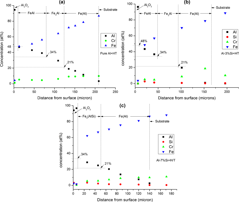
Elemental depth profiling of oxidation heat treated specimen using EDX analysis technique: a depth profile of sample A-HT; b depth profile of sample B-HT; c depth profile of sample C-HT
Diffusion aluminide layer
The high temperature oxidation heat treatment not only converts the surface Al atoms to oxidise but also leads to diffusion of Al and Fe atoms. As per the aluminide case depth shown in Fig. 4, it can be understood that with increase in Si concentration, the diffused aluminide case depth decreases. The A-HT type samples indicated a case depth of ∼190 μm with FeAl and α-Fe(Al) phases, B-HT type samples showed ∼160 μm with FeAl, Fe3Al and α-Fe(Al) phases, while the C-HT type samples containing 7%Si in Al showed the lowest with ∼132 μm case depth with Fe3(AlSi) and α-Fe(Al) phases. These results are in good agreement with those reported by Bindumadhavan et al.23 for different Si concentrations in Al melt. Figure 6 shows case depth as a function of Si content in Al melt. The error bar reduction at higher Si concentrations (types B-HT and C-HT) as shown in Fig. 6 is due to a homogenous interface as observed in the as coated condition, while those in pure Al contained an inhomogeneous interface layer. It may be noted that the difference of the coating thickness of as coated HDA samples (types A and C) was not significant as compared to the heat treated samples as shown in Fig. 6. The reason attributed to the significant reduction of diffusion depth is the increased Si content, and similar observations have been reported by Cammarota et al.22 Si has been found to hinder diffusion of Al and substrate due to complex Fe–Al–Si compound formation. It has also been reported7 that in Fe3Al, Si replaces the Al atoms, and hence, the Al concentration is reduced and the same can be identified by the shift of the (211) plane of FeAl or (422) plane of Fe3Al as indicated in Fig. 7. Pint et al.24 demonstrated that an increase in Al concentration in Fe–Al phase can be observed from the shift of (211) or (422) peak to lower bragg angles (2θ ), i.e. the d values increase with higher Al concentration in the phase. As shown in Fig. 7, with the increase in Si content, the (211) or (422) peak as detected in XRD shifts to higher bragg angles, i.e. lower d values. This reduction in the d value indicates that Al concentration has been reduced in high Si alloyed melt samples (i.e. types B-HT and C-HT). Since diffusion is a concentration dependent phenomena, this reduction in Al concentration at a given depth due to Si addition might be one of the reasons for reduced aluminide case depth in Al–3Si (B-HT) and Al–7Si coated (C-HT) samples. This is also one of the reasons for the Fe rich phases [Fe3Al, Fe3(AlSi), α-Fe(Al)] in higher Si containing samples (B-HT and C-HT type samples) as compared to the FeAl phase in pure Al coated samples (A-HT type samples) observed by XRD and EDX results. It is important to note that XRD alone cannot differentiate between FeAl and Fe3Al phases, and hence, the same has been confirmed using EDX technique. The depth profiling by EDX (Fig. 5) indicates approximate thickness of various phases in diffused aluminide case, namely, FeAl, Fe3Al and Fe(Al) based on their equilibrium Al composition (at-%) limits as per Fe–Al phase diagram. These estimated thicknesses are in close agreement with the case depth marked with dotted line in Fig. 4. It is important to note that the thickness of Fe(Al) phase increases with increasing Si concentration, which indicates lower Al activity. In such cases, once FeAl or Fe3Al phases are formed, inward Al diffusion into steel substrate becomes the predominant diffusion process, and this diffusion has probably led to the formation of pores in the iron aluminide case, i.e. towards the coating side. Similar observation was reported by Xiang et al.25 for porosities formed due to faster inward diffusion of Al. Figure 4 clearly shows such diffusion porosities towards coating side at higher Si concentrations. Such Kirkendall porosities are undesired from tritium permeation perspective and needs to be eliminated to make the coating suitable for TBM application.26, 27 Such porosities can be removed by high pressure (i.e. by hot isostatic pressing).9, 27 Another important aspect is the effect of heat treatment conditions on the core microstructure. It is understood that though martensitic structure can be achieved in P91 by air cooling,28 a stabilisation treatment such as normalising and tempering is required to reestablish the core microstructure. Work reported by Glasbrenner and Wedemeyer27 confirms that an iron aluminide case with a stabilised core of 9Cr steel can be generated for TBM applications without affecting the iron aluminide case composition. The steel with the presently reported heat treatment needs to undergo normalising and tempering treatment for establishing the core microstructure.
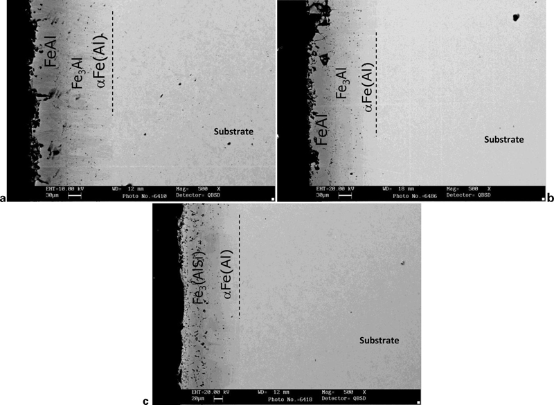
Cross-section BSE micrographs of oxidation heat treated samples with a pure Al coating (A-HT), b Al–3Si coating (B-HT) and c Al–7Si coating (C-HT): dotted line indicates case depth of aluminide case
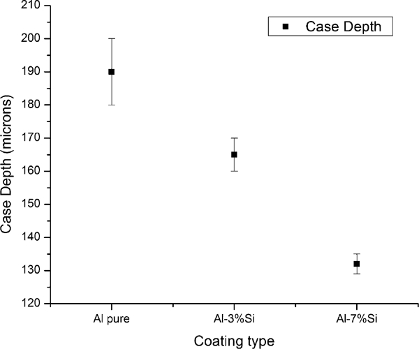
Plot of diffused aluminide case depth as function of Si content in aluminising bath after oxidation heat treatment
X-ray diffraction plot for (211) peak of aluminised and heat treated 9Cr–1Mo steels: (211) peak shifts to higher angles with increase in Si concentration
Conclusion
From the above observations, it is concluded that addition of Si promotes the transformation from γ to θ and θ to α phase. For the same temperature and time duration, pure Al coated samples indicated metastable transition alumina (γ and θ ), while 7%Si alloyed Al coatings indicated a stable alumina (α-Al2O3) phase. It is important to note that γ-Al2O3 and θ-Al2O3 grow by outward diffusion of cations (Al3+), while α-Al2O3 grows by inward diffusion of anions (O2−).29 – 31 In this work, the possible cause for the occurrence of stable α phase at 7%Si content is the physical blocking of outward migrating cations by Si in the growing oxide films. It can be concluded that Al–7 wt-%Si coating yields a protective α-Al2O3 layer and also helps in reducing the iron aluminide layer case depth, which is beneficial from reduced activation point of view for fusion reactor applications. This information shall be useful for future optimisation work on validation of aluminised coatings for compatibility against liquid Pb–17Li for application to TBM. However, the coating further needs to be optimised for eliminating kirkendall porosity and stabilising core microstructure to make it suitable for TBM applications. Efforts to resolve this issue are being pursued.
Footnotes
Acknowledgements
The above work was carried out under the test blanket module programme of the Institute for Plasma Research, and the authors are thankful to Mr E. Rajendrakumar for continued support in this activity. The help of Mr V. Shah, Mr H. Suthar and Mr A. Ranka of Indus Institute of Technology and Engineering, Ahmedabad, and Mr V. Nayak of FCIPT in conducting the experiments is sincerely acknowledged. The support from Mr G. Jhala in preparing the cross-section mount is also thankfully acknowledged. The authors gratefully acknowledge the support from the Department of Metallurgical Engineering and Materials Science Department, Indian Institute of Technology Bombay, for conducting the XRD tests.