
Abstract
The amorphous nickel–phosphorus coating and its carbon nanotube (CNT) composite coating were prepared by brush electroplating technology. After 1 h heat treatment at 400°C, the coatings translated into the crystalline state, which consists of α-Ni matrix and Ni3P precipitated phase. The results of energy dispersive X-ray, X-ray diffraction analysis and differential thermal analysis showed that, due to CNTs, the phosphorus content in the coating decreased from 8·42 to 7·34 wt-%. Carbon nanotubes also had an effect on crystallisation kinetics of the amorphous coating. The crystallisation activation energy in Ni–P/2 g CNT composite coating was 25 kJ mol−1 higher than that in Ni–P coating. The time and temperature of the 50% crystallised were 5 min longer and 29°C higher respectively than that in Ni–P coating. Further study showed that CNTs played a role in obstruction in the crystallisation because CNTs block nucleation and growth of crystallisation for Ni3P phase.
Introduction
Under the conditions of high load and high speed, the temperature of friction surface rises significantly, then the softening of material results in an increased friction coefficient and abrasion loss and even scuffing or seizure. Therefore, under heavy friction condition, the material is expected to perform against high temperatures in order to ensure good friction and wear resistance. A layer of the composite coating with the characteristics of high hardness and heat resistance produced on the surface of material by electroplating is an effective way to improve the friction and wear properties.
Carbon nanotubes (CNTs) have super-strong mechanical characteristics and unique hollow structures. Carbon nanotubes as reinforcements are increasingly attracting scientific and technological interest because of their unique chemical and physical properties for producing composites of metallic and non-metallic constituents. Some results showed that the Ni–P/CNT composite coating exhibited not only higher wear resistance, but also lower friction coefficient than the Ni–P/SiC and Ni–P/graphite coatings,1 – 3 and even higher corrosion resistance than the amorphous Ni–P coating.4 – 6 However, there is no thorough research in literatures on the effects of CNTs on crystallisation in amorphous Ni–P composite coatings.
The present works mainly study the effects of CNTs on crystallisation kinetics and discuss how the CNTs influence the phosphorus content, crystallisation activation energy, crystallisation time and temperature in the Ni–P electroplating coatings. It is expected that the results can help us to get a better understanding of the important roles of the CNTs on crystallisation.
Experimental
Compositions of brush electroplating bath
Components of the brush electroplating bath are as follows: nickel sulphate (NiSO4.7H2O), 200–250 g L−1; nickel chloride (NiCl), 40–60 g L−1; sodium hypophosphite (NaH2PO2.H2O), 20–30 g L−1; additives, 60–100 g L−1; and suitable amounts of surfactants. Its acidity–alkalinity (pH) is 1·5–2·5.
For the comparison with Ni–P coating, CNTs of 2 g L−1 were added into the bath to prepare Ni–P/CNT composite coating.
Carbon nanotubes
Carbon nanotubes are prepared by catalytic chemical vapour deposition (CCVD).7 After purification, the carbon tube wall is clear, with few defects and impurities. There are only a few amorphous carbons and graphite sheets attached on CNTs. Carbon nanotubes are long and slightly curved (as shown in Fig. 1). The measured length is >700 nm. The inner diameter is approximately 5–20 nm, and the outer diameter is about 20–40 nm.
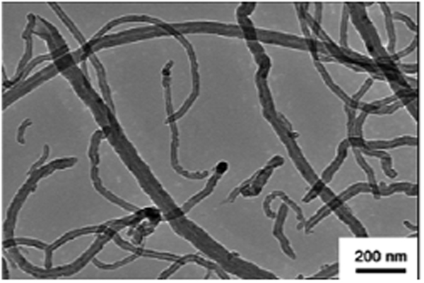
Image (TEM) of CNTs prepared by CCVD
Brush electroplating process
After CNTs of 2 g L−1 were added into the bath, a 10 000 rev min−1 electric mixer was used to agitate for 5 min. A uniformly dispersed and suspended compound bath was obtained. The substrate material is carbon steel of 0·45%C.
The pretreatment process of the sample was as follows: electrocleaning (+12 V)→activation (±12 V)→second activation (±18 V)→nickel plating (±12 V). Plating temperature is room temperature, current is 3–6 A, relative moving speed is 8–12 m min−1 and voltage is 12 V.
Composition of plating coating
The coating composition was analysed by Hitachi S-530 spectrometer.
Differential thermal analysis
The differential thermal analysis was applied to the amorphous Ni–P coating and Ni–P/2 g CNT coating powder. It was carried out by the DuPont 9903 thermal analyser with a flowrate of 50 mL min−1 nitrogen protection. Each feeding amount was 2–5 mg. Alternating temperature analysis method was adopted, for which the heating temperature increased 2, 5, 10, 20 and 50°C min−1 respectively.
Results and discussion
Composition and phase analysis of coatings
By energy disperse spectroscopy, the chemical composition and its relative amount of Ni–P coating were measured as follows: 0·91O–8·42P–90·61Ni (wt-%). However, those of Ni–P/2 g CNT composite coatings were measured as follows: 2·36C–0·90O–7·34P–89·35Ni (wt-%).
Thus, the conclusion can be reached that the P content of coating decreases due to the addition of composite particles into the same Ni–P alloy plating solution. Other scholars also found this phenomenon8,9 and thought that it was the composite particles that hampered the electrodeposition of phosphorus atoms.
It is considered that the plating voltage and current conditions have little effect on the phosphorus content of the coating, while the NaH2PO2 content in the bath is the decisive factor.10,11 When the phosphorus content of the coating is >7%, an amorphous structure of coating is obtained; otherwise, a crystalline structure of coating forms. This is because the saturation of the phosphorus atoms in the substitution solid solution of nickel is ∼6 wt-%. In this experiment, the result of X-ray diffraction analysis analysis proved that the Ni–P coating was amorphous structured since there was no clear X-ray diffraction peak of crystals shown in the curve of 25°C in Fig. 2.
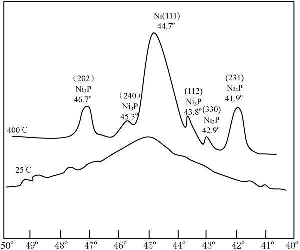
X-ray diffraction analysis curves of Ni–P coating at room temperature (25°C) and after 400°C heat treatment
Amorphous Ni–P coating is in an unstable phase. With the increase in heating temperature, the amorphous state converts to the crystalline state. It is generally believed that when the temperature is >300°C, crystallisation begins. Simultaneously, the fcc Ni and Ni3P phases appear.12,13 At a temperature of >400°C, the crystallisation process finishes and the stable structure consists of Ni and Ni3P. The phases cannot be changed by the increasing temperature or the prolonging holding time. However, the relative amount and size of the phases can be altered by these mentioned factors. Figure 3 shows that a stable crystalline state of the coatings is obtained after 400°C/1 h heat treatment. It is obvious that Ni3P phase in Ni–P coating occupies a larger proportion than that in Ni–P/2 g CNT coating.
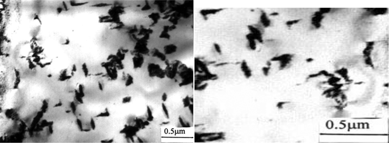
Images (TEM) of coatings after 400°C/1 h heat treatment: a Ni–P coating; b Ni–P/2 g CNTs coating
Crystallisation kinetics of Ni–P/CNT composite coatings
When heated, the amorphous Ni–P coating can transform the imbalanced amorphousness into a balanced crystalline and greatly change its performance. The change is positive to the parts that work at high temperature or under heavy friction. Under these circumstances, the coating is heated and then crystallises gradually. It is beneficial to improve hardness and wear resistance of the coating. Figure 4a and b depicts the typical variable–temperature analysis curves of Ni–P/2 g CNT coating and Ni–P coating respectively. It can be observed intuitively that the released heat is less and crystallisation temperature is higher in Ni–P/2 g CNT coating than those in Ni–P coating.
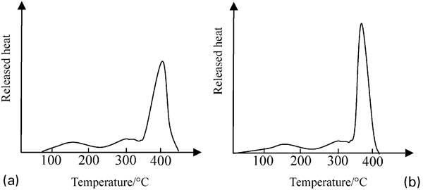
Temperature changing analysis curve: a Ni–P/2 g CNTs coating; b Ni–P coating
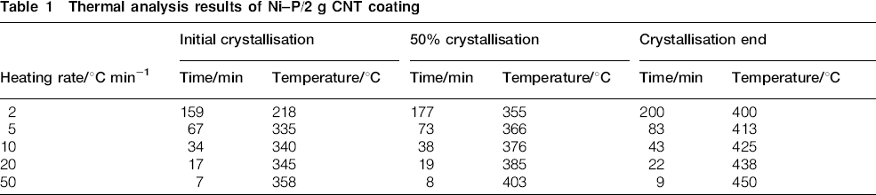
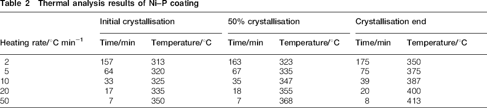
According to the thermal analysis curves, the time coordinates of the crystallisation starting time, end time and 50% coating crystallising time were obtained as shown in Tables 1 and 2.
Thermal analysis results of Ni–P/2 g CNT coating
Thermal analysis results of Ni–P coating
Constant heating rate crystallisation process of coatings can be expressed by Kissinger equation as follows
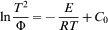
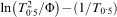 diagrammatic curves were accomplished, which demonstrated an approximate linear relationship. According to the slopes of the fitting lines for Ni–P/2 g CNT coating and Ni–P coating, which are 2·2×104 and 2·5×104 respectively, the activation energies of crystallisation in 50% of crystalline transition, which are regarded as the average activation energy of the entire crystallisation process, were calculated as follows:
Ni–P/2 g CNT coating: E = 209 kJ mol−1
Ni–P coating: E = 184 kJ mol−1
It is significant that the crystallisation activation energy is taken as an index describing the stability of amorphous materials. For a stable amorphous alloy system, the activation energy of crystallisation is generally 400–600 kJ mol−1.14 Although the crystallisation activation energy of composite coatings can be increased by the CNTs, the coating is in an unstable state.
According to the data of Tables 1 and 2, temperature changing crystallisation was shown as Fig. 5. It can be seen that the crystallisation starting temperature of Ni–P/2 g CNT coating is 10°C higher than that of the Ni–P coating. For the 50% of coating crystallisation temperature and the crystallisation end temperature, average values of 29 and 40°C are given respectively. When it comes to the crystallisation starting time, the two kinds of coatings depict almost the same characteristic. However, in the case of Ni–P/2 g CNT coating, the time of 50% crystallisation extends 5 min longer than that of the Ni–P coating, while the crystallisation end time takes 7 min extra. This indicates that CNTs have an effect on the crystallisation process of the Ni–P amorphous coatings. The same effects were found in other materials such as Mg–Cu–Gd bulk metallic glass.15 It is believed that the CNTs increase the energetic barrier for the glass transition.
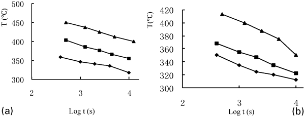
Crystallisation curve (▴: initial crystallisation; ▪: 50% crystallisation; ♦: crystallisation end): a Ni–P/2 g CNTs coating; b Ni–P coating
According to the theory of crystallisation kinetics, the crystallisation process is a crystal nucleation and growth process. The amorphous matrix encounters a greater energy barrier of nucleation and growth in the process of crystallisation when CNTs are added. Thus, the crystallisation only occurs under high temperature conditions, which is consistent with the results above that the measured values of crystallisation activation and crystallisation temperature increase. According to the deposition mechanism of ordered atom group offered by Lu,16 crystallisation consists of the following processes: formation of ordered atom clusters in the amorphous region, crystal nucleation and growth. When crystallisation begins, first, the ordered atom clusters form due to atom diffusion and migration. On one hand, the shear depositions of atom rows occur at both ends of the atom clusters, resulting in the growth of the atom clusters. On the other hand, crystal nucleus is produced as a result of atom diffusion and migrates to atom clusters. During the process of crystal nucleus growth, there are diffusion and migration of atom and shear depositions of atom rows. Because of the interaction force between atoms, during the rearrange of the atoms, the location adjustment will have certain interaction to the surrounding atoms. When Ni3P nucleates, the embryos grow into the nuclei by the shear deposition of tiny atomic groups at the embryos forefront. Carbon nanotubes hinder the shear displacement of atomic groups; therefore, the nucleation and growth of the crystal nucleus in the force field of CNTs overcome a higher shear activation energy. Consequently, it is more difficult to form nuclei in the amorphous matrix.
In fact, the CNTs further impede the growth process after nucleation because nuclei grow in three dimensions, with wider ranging effects and a greater interaction with the force field of CNTs. This is why greater crystallisation activation and a higher crystallisation temperature are demanded to complete the crystallisation process. It is consistent with the experimental results that the times and temperatures at 50% crystallisation and crystallisation end of Ni–P/2 g CNT coating are longer and higher than that of Ni–P coating respectively. In Ref. 17, the crystallisation activation energy, measured from a 2 wt-%CNT iron phosphorus amorphous composite that was prepared by rapid solidification, increased by ∼40%, and the crystallisation end activation Ee is 32·5 kJ mol−1 higher than the crystallisation starting activation Es. The result suggests that the later stage of the crystallisation process has to overcome a larger energy barrier than the previous stage due to CNTs.
In the crystallisation process, the longer the incubation period of nucleation extends, the more crystalline cores form from the short range order clusters. Next to this, the grains of crystallisation coating become thinner and compacter, leading to the improvement of the mechanical performance of the coating. It applies the same effects when the nucleation grows slower.
Conclusion
In this experiment, the 8·5 wt-% amorphous nickel–phosphorus coating and its CNT composite coatings with 7·3 wt-% amorphous were prepared by brush electroplating technology. After 1 h heat treatment at 400°C, the coatings transform into the crystalline state and the stable microstructure is α-Ni matrix and Ni3P precipitated phase.
Addition of CNTs has an effect on the crystallisation kinetics of amorphous nickel–phosphorus coating. The crystallisation activation energy of Ni–P/2 g CNT coating is 25 kJ mol−1 higher than that of Ni–P coating, the time of 50% crystallisation extends by an additional 5 min and the temperature of 50% crystallisation increases by 29°C. This indicates that the CNTs hinder the crystallisation process of the nickel–phosphorus coating. The main mechanism is that the force field of CNTs impedes the crystallisation nucleation and the growth of Ni3P phase.
Footnotes
Acknowledgements
The financial support of the project by Guangdong Natural Science Foundation (grant no. 8151802904000001) is acknowledged.