
Abstract
In this work, the cavitation silt erosion behaviour and the mechanisms of high velocity oxygen fuel sprayed nickel based alloy coatings under different sediment concentration conditions were studied. The coating with low porosity of 0·88±0·06% consists of γ-Ni, Ni3B, Cr23C6, Cr7C3 and WC phases. The mass loss and mass loss rate of the coatings are found to increase with sediment concentration increasing as a result of more interaction between sand particles and specimen. For the coating in 0 kg m−3 solution, crater and lip are observed on the eroded surface. For the coating in 20 kg m−3 solution, signatures of crater and microcutting are observed. When the sediment concentration rises up to 40 kg m−3, a process of crater and microcutting first, followed by ploughing and microcutting, is observed. The results suggested that the cavitation silt erosion mechanism for the coating is a ductile erosion mode.
Introduction
Among the available protective coating materials, nickel based alloy coatings have a unique combination of engineering properties, which belong to the Ni–B–Si system with the addition of other alloying elements.1 – 3 Nickel based alloy coatings are extensively used to protect components whose surface is subjected to wear and corrosion conditions, such as valves, propellers, roller, piston rods, heat exchangers, extruders, turbines, agriculture machinery and wearing plates.1 – 5 Generally, thermal spraying techniques frequently used for depositing nickel based alloy coatings include arc spraying, high velocity oxygen fuel (HVOF) spraying, plasma spraying and flame spraying.5 – 9 However, the HVOF spraying is capable of preparing coatings with lower porosity, less decarburisation, lower oxide content, higher hardness and superior bond strength than many other thermal spraying methods due to the lower operating temperature and higher velocity.10 – 12
A large number of researches have reported on HVOF sprayed nickel based alloy coatings. Carrasquero et al. found excellent fretting wear resistance in an HVOF Ni–Cr based alloy deposited on SAE 1045 steel in comparison to the uncoated substrate.6 Guilemany et al. demonstrated the superior erosion–corrosion properties of nickel based HVOF sprayed coating for protecting steel exchanger pipes against the erosion produced by the impact of the ashes in flue gas.7 Sidhu et al. showed that the HVOF sprayed NiCrBSi coating has better hot corrosion resistance than that of Fe based superalloys in a molten salt (Na2SO4–60V2O5) environment at 900°C.13 An experimental programme was carried out by Gil and Staia, who found that the HVOF parameters (i.e. spraying distance, the fuel/oxygen ratio and the powder feedrate) have a significant effect on the porosity and corrosion resistance of NiWCrBSi HVOF sprayed coatings.14 Most of the reported work describes in detail the wear and corrosion performance of HVOF sprayed nickel based alloy coatings. The excellent properties of HVOF sprayed nickel based alloy coatings are yet to be explored in hydraulic machinery, where they are subjected to the combined action of cavitation erosion and silt erosion (CSE).15 – 18 This type of erosion has been observed in pumps and water turbines in the basin of the Yellow River, China.
In the present work, a nickel based alloy coating was deposited by HVOF spraying. The coatings were characterised based on microstructures and physical properties and further evaluated for their CSE behaviour and mechanism under different sediment concentration conditions.
Experimental
A nickel based alloy powder was used in this study. Its nominal components are listed in Table 1. Figure 1 shows the SEM morphology of this starting powder at a low magnification of ×500 (Fig. 1a) and a high magnification of ×2000 (Fig. 1b) respectively. The powder was characterised by near perfect spherical particles with a size range of 10–45 μm, as shown in Fig. 1. The substrate material of the coating was stainless steel 1Cr18Ni9Ti. Before spray, the substrate samples were degreased and grit blasted with 30 meshes Al2O3. The HVOF spray experiments were carried out with a commercial HVOF (Praxair Tafa-JP8000, USA) thermal spray system, which was performed using kerosene as the fuel gas and argon as the powder carrier gas. The main spraying parameters were conducted at a kerosene flowrate of 22·7 L h−1, an oxygen flowrate of 940 L min−1, an argon carrier gas flowrate of 0·24 L h−1, a powder feedrate of 5 rev min−1 and a spraying distance of 350 mm. The coatings were built up to a thickness of 180±10 μm.
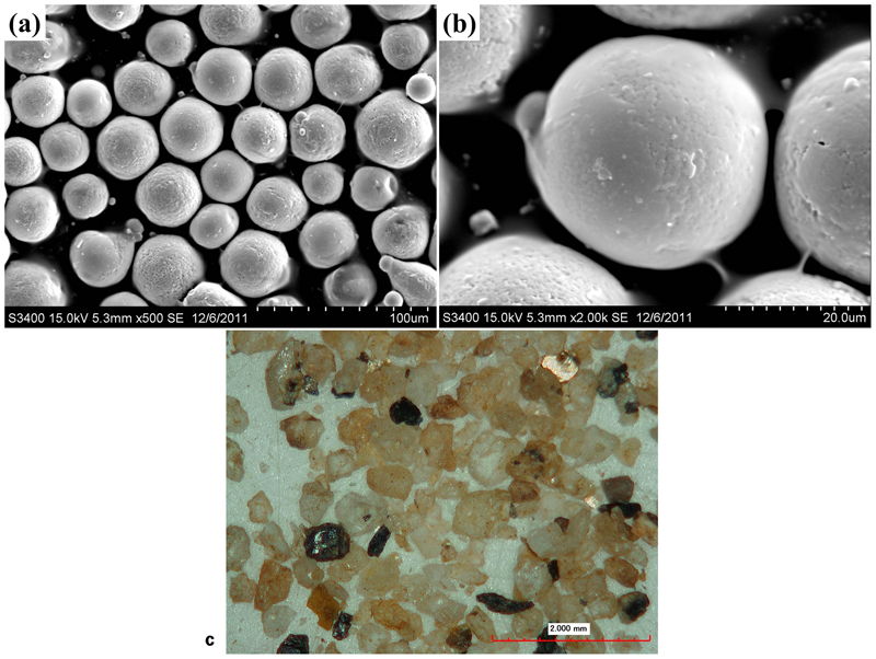
Images (SEM) of powder with magnification of a ×500 and b ×2000 and c macromorphology of sand particle
Chemical composition of nickel based alloy powder
The phase composition of the coating was identified by X-ray diffraction (XRD, Bruker D8-Advanced, Germany) with Cu Kα radiation (λ = 1·54 Å) and 0·02° step. Microstructures of the coating and its eroded surface were observed by scanning electron microscope (SEM, Hitachi S-3400N, Japan). The macromorphology of the sand particles used in the present study was observed by a digital microscope (Hirox KH-7700, USA). The porosity of the coating was calculated using image analysis software on an optical microscope (Olympus BX51M, Japan). Microhardness tests were performed using a Vickers microhardness tester (HXD-1000TC) with a load of 0·98 N and a dwell time of 15 s. Twenty porosity and hardness measurements were taken of the coating section and averaged to ensure good reproducibility.
Cavitation erosion and silt erosion tests were carried out using a vibratory cavitation apparatus coupled with an independent stirrer, the detailed procedure of which can be found elsewhere in the literature.15 The vibratory frequency and double vibratory amplitude were 19±1 kHz and 60±5 μm respectively. All the screw specimens were ground and polished to a mirror-like surface with an average surface roughness Ra = 0·02 μm, cleaned with acetone in an ultrasonic bath, dried by hot air and weighed by an electronic balance. Then, the screw specimen with the nickel based alloy coating was attached to the free end of the horn. The uncoated substrate (stainless steel 1Cr18Ni9Ti) was also selected as comparison material. Fresh water with a sediment concentration of 0, 20 and 40 kg m−3 was used as the test liquid and changed every 1 h to study the combined action of cavitation erosion and silt erosion on the coatings. Figure 1c shows the macromorphology of the sand particles used in the present study, which clearly exhibits the angularity of the sand and particle size range of 200–600 μm. The stirrer was used to continuously mix the water and sand particles in order to ensure a consistent sediment concentration. In the testing process, the beaker was surrounded by the flowing cooling water and the test solution was kept at a temperature of 25–30°C. After each test period (1 h), the specimen was degreased, rinsed, dried and weighed to determine mass loss. The accuracy of the mass balance was 0·1 mg.
Results and discussion
Characterisations of coating
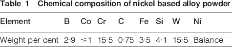
Figure 2a presents the XRD pattern for the surfaces of the HVOF sprayed nickel based alloy coating. A broad diffraction halo appears ∼2θ of 44° in the coating, which indicates the formation of an amorphous/nanocrystalline phase during the thermal spray process. It can be identified from Fig. 2a that the coating consists predominately of γ-Ni [Joint Committee on Powder Diffraction Standards (JCPDS) no. 04-0850] solid solution and a certain amount of Ni3B (JCPDS 73-1792), Cr23C6 (JCPDS no. 35-0783), Cr7C3 (JCPDS no. 36-1482) and WC (JCPDS no. 25-1047), which are in accord with those reported in the literature for this kind of nickel based alloy.19 – 21
a X-ray diffraction pattern of as sprayed coating; SEM images of transverse section of as sprayed coating: b lamellar morphology, c lamella and pores, d pores and e hard phases and f variation in microhardness across coating and substrate
Figure 2b–e illustrates the typical microstructures of the polished cross-sections of the coating. The average thickness of the coating is found to be 180 μm, as shown in Fig. 2b. The microstructure revealed that the coating has a highly dense structure. Figure 2c shows the presence of the lamellated structure, which almost parallel the substrate surface. A similar result has been observed in our previous investigations.17, 18 Furthermore, it can be observed from Fig. 2d and e that the fine hard phases are distributed uniformly in the coating accompanying a low degree of porosity. The average porosity value of the coating measured by the image analysis software is 0·88±0·06%.
Figure 2f shows the microhardness distribution along the depth direction of a cross-section of the coating and the substrate. The average microhardness of the coating is 1100±95 HV, which is ∼5·5 times of the substrate (200±18 HV). The high microhardness of the coating is attributed to the low porosity and the presence of hard phases shown in the XRD spectrum. It can be seen that the microhardness of the substrate near the interface is higher than that far from the interface, which is mainly associated with the workhardening resulting from the impact of the melted or semimelted particles and grit sand on the substrate.22
Characteristics of CSE
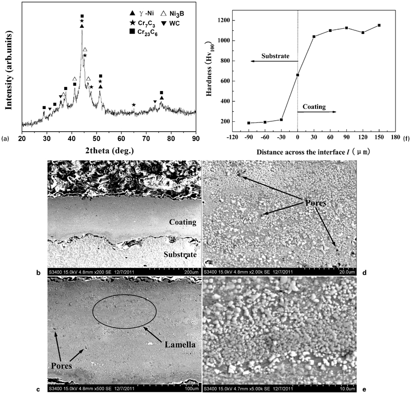
Figure 3 shows the cumulative mass loss and mass loss rate of the coating and reference stainless steel 1Cr18Ni9Ti with respect to time in three sediment concentration solutions (i.e. 0, 20 and 40 kg m−3) under CSE for 20 h. It is evident that the cumulative mass loss of all samples increases with erosion time (Fig. 3a and c). However, the mass loss rate of the coating samples increases first, decreases sharply during first few hours and shows almost a steady state after 12 h (Fig. 3b). Although the surface of coating samples has been ground and polished with the same surface roughness before eroded, it may thus suggest that the uneven surface of samples and the initiation of the craters could raise the mass loss rate at the beginning of test.23, 24
a cumulative mass loss and b mass loss rate as function of time for coating, c cumulative mass loss as function of time for stainless steel 1Cr18Ni9Ti, d mass losses for coating and stainless steel 1Cr18Ni9Ti after 20 h in different sediment concentration conditions: 0, 20 and 40 kg m−3; CSE characteristic of as sprayed coating in 0 kg m−3 sediment concentration solution (eroded 20 h); e boundary of CSE region and f CSE region
After eroded for 20 h (Fig. 3d), the mass losses of the coating in 0, 20 and 40 kg m−3 solutions were 12·8, 16·9 and 22·8 mg respectively, whereas the mass losses of the stainless steel 1Cr18Ni9Ti in 0, 20 and 40 kg m−3 solutions were 24·1, 25·3 and 38·0 mg respectively. It is shown that the HVOF sprayed nickel based alloy coating exhibits apparently higher resistance than the reference stainless steel 1Cr18Ni9Ti. Furthermore, the mass loss rates of the coating in 0, 20 and 40 kg m−3 solutions were 0·64, 0·85 and 1·14 mg h−1 respectively. A simple comparison of mass loss indicates that the CSE mass loss of the coating in 40 kg m−3 was 1·35 and 1·78 times that in 20 and 0 kg m−3 respectively. However, the evaluation of CSE properties of the coating is not only based on the mass loss data but also need further observation of the micromorphology.
Figures 3e and f, 4 and 5 present the surface morphologies of the coating after CSE for 20 h in different sediment concentration conditions. Two typical regions of the eroded specimen including the CSE region and the boundary of the CSE region were examined under SEM, which had been introduced in our previous work.18
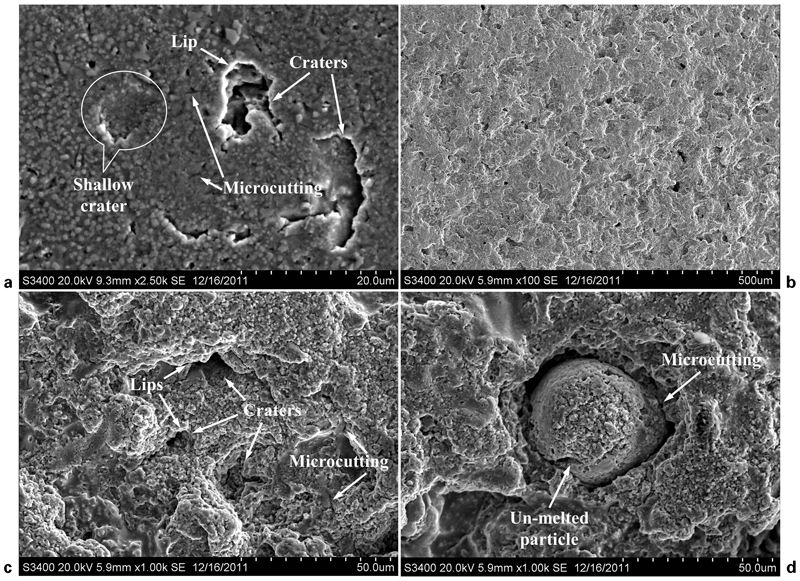
Cavitation erosion and silt erosion characteristic of as sprayed coating in 20 kg m−3 sediment concentration solution (eroded 20 h):
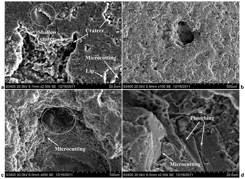
Cavitation erosion and silt erosion characteristic of as sprayed coating in 40 kg m−3 sediment concentration solution (eroded 20 h):
The surface SEM feature of the coating eroded in 0 kg m−3 solution is shown in Fig. 3e and f. As shown in Fig. 3e, lips around the crater were formed by repetitive impacts of the bubble collapse on the micropores. Figure 3f suggests that the eroded surface was relatively smooth at the CSE region.
Figure 4 shows surface micrographs of the coating after CSE for 20 h in 20 kg m−3 solution. Lips, craters and microcutting are observed at the boundary of the CSE region (Fig. 4a). The presence of craters with different depth and shapes seems to be associated with different shapes and impingement angles of the sand particles. At the CSE region, the eroded surface is relatively uniform (Fig. 4b), including number of lips, craters and microcutting labelled in Fig. 4c. Figure 4d indicates that the microcutting occurred more often in the matrix around the unmelted particle. It may thus suggest that the crater and microcutting are responsible for material removal.
The appearance of the damaged surface of the coating after CSE for 20 h in 40 kg m−3 solution is shown in Fig. 5. The eroded surface at the boundary of the CSE region (Fig. 5a) exhibited that the erosion mechanisms are similar to those in 20 kg m−3 solution, while the degree of degradation is much higher. From Fig. 5b, it can be noticed that the surface was roughened with a 200 μm crater in the centre of the CSE region. Craters along with lips are much larger and deeper compared to Fig. 4b. The magnified micrographs of the 200 μm crater, shown in Fig. 5c and d, indicate that material eroded from the surface showed the presence of wear marks that are due to ploughing and microcutting. Figure 5d shows a magnified micrograph of the region of Fig. 5c, which is marked by ellipse. The ploughing marked in Fig. 5d confirms the fact that the unmelted particles within the matrix are too soft to resist the impact wear of sand particle. Consequently, the mechanism responsible for material removal of the coating is crater and microcutting first, followed by ploughing and microcutting. Cutting and craters surrounded by lips in some previous works were interpreted as a common feature of ductile erosion.25 – 27 From the above results, it is suggested that the CSE mechanism for the coating is a ductile erosion mode.
Conclusion
The HVOF sprayed nickel based alloy coating has a compact microstructure with an average thickness of 180 μm and average porosity of 0·88±0·06 %. The coating consists of γ-Ni, Ni3B, Cr23C6, Cr7C3 and WC phases. The enhanced microhardness of the coating (1100±95 HV) is attributed to the presence of uniformly distributed carbides and borides in the matrix.
The CSE resistance of the coating is higher than that of the stainless steel 1Cr18Ni9Ti. In all the cases, the mass loss and mass loss rate of the coatings were found to increase with sediment concentration increasing as a result of more interaction between sand particles and specimen.
Crater was responsible for material removal of the coating in 0 kg m−3 solution. Crater and microcutting were responsible for material removal of the coating in 20 kg m−3 solution. However, the material removal of the coating in 40 kg m−3 solution is crater and microcutting first, followed by ploughing and microcutting. The CSE mechanism for the coating is a ductile erosion mode.
Footnotes
Acknowledgements
The research was supported by the Marine Renewable Energy Fund Project of the State Oceanic Administration (grant no. GHME2011CX02) and the Research and Innovation Project for College Graduates of Jiangsu Province (grant no. CXLX12_0244).