
Abstract
This work aims to show the characterisation of Cr–V–N coatings, with the varied amounts of Cr and V. CrN, VN and Cr–V–N coatings were deposited onto silicon and XC100 steel substrates by reactive radio frequency magnetron sputtering and characterised with X-ray diffraction, X-ray photoelectron spectroscopies, energy dispersive X-ray spectroscopy, scanning electron microscopy, nanoindentation, pin on disc tribological tests and scratch tests. The residual stress was calculated using the Stoney formula. Compared to the CrN system, the Cr–V–N films presented a rough surface based on pyramidal morphology. A hardness of 19·53 GPa and a friction coefficient of 0·55 were obtained for CrN; in contrast, Cr–V–N coatings presented a weak hardness of 6·23 GPa. In the case of wear against a 100Cr6 ball, the Cr–V–N films were completely removed from the substrate, even though the Cr–V–N coating presented a low friction coefficient (0·39). However, the VN film showed good tribological performance.
Notation:
atomic percentage
(argon/nitrogen) gases
the line width (FWHM) in radians
grain size
Young's modulus
film thickness
substrate thickness
Young's modulus of the substrate
electron volt
diameter
hardness
Hertz
cohesive failure critical load
adhesion failure critical load
Newton
pressure
curvature radius of the sample after deposition
curvature radius before deposition
average roughness
root mean square roughness
friction coefficient
X-ray wavelength of cobalt
Bragg's angle
the residual stress
Poisson's ratio of the substrate
Introduction
Many studies have been dedicated to Cr based ternary nitrides, such as Cr–Al–N 1 and Cr–Zr–N. 2 These compounds have been developed rapidly, and their excellent properties (high oxidation resistance and a very low surface roughness, compared to the Cr–N system) were reported in many papers. Typically, the tertiary elements that have been chosen are based on the properties of the binary systems.
The addition of V to improve the tribological properties of CrN films has been studied successfully. 3 In addition, the excellent mechanical properties were achieved for CrN/VN multilayers deposited by magnetron sputtering. 4 Recently, vanadium nitride has generated a great deal of interest because it can easily oxidise at high temperatures and become a good lubricant film.5,6 The coefficient of friction of a Cr–V–N coating, with a hardness of 15 GPa, was 0·5 when sliding against AISI 52100 steel at a room temperature, according to Uchida et al. 7 Moreover, the coefficient of friction of Cr–Al–V–N coatings sliding against the same steel decreased from 0·6 at the room temperature to 0·05 at 800°C due to the formation of vanadium oxides. 8 When vanadium is mixed with other transition metal nitrides like CrN or TiN, 3 the tertiary compound can at present improve mechanical properties comparing the constituent binary materials. For example, the ternary Cr50V50N nitride shows a sliding performance instead of the binary CrN and VN systems. 7 Ti77V23N shows a higher hardness in comparison to the binary TiN and VN systems, while Ti22V78N had a lower hardness comparing to the binary TiN system. 9
The purpose behind the present work is to study the properties of Cr–V–N films deposited by reactive radio frequency (RF) magnetron sputtering. Thus, the ternary Cr–V–N films are compared to the binary CrN and VN coatings. By this comparison, the influence of vanadium content on the structure, morphology, mechanical and tribological properties of the Cr–N system can be determined.
Experimental
Cr–V–N thin films were deposited by RF magnetron sputtering (NORDIKO type 3500, 13·56 MHz) in an Ar/N2 mixed atmosphere on Si (100) coupons (10 × 10 mm2, 380 μm thick) and polished XC100 steel discs (d = 15 mm, 3 mm thick). A detailed description of the sputtering system has been reported elsewhere.
10
The chamber was pumped down to a base pressure under 2 × 10− 5 Pa before the depositions. The total pressure during the deposition was fixed to 0·4 Pa with the nitrogen partial pressure PN2 set at 0·1 Pa (
 is 0·3 Pa). The typical composition of XC100 steel is as follows: 0·95 to 1·05 wt-%C, 0·5 to 0·8 wt-%Mn, 0·05 wt-%S, 0·25 wt-%Si, 0·035 wt-%P and S, with Fe as the balance. The average roughness Ra of XC100 steel substrates is ∼30 nm. The distance between the confocal arranged targets and the substrate was 80 mm. Before deposition, the substrates were situated under Ar+ ions bombardment for 5 min at − 1000 V and at 10 μbar. During deposition, the substrate temperature was estimated around 150–350°C. In this study, Cr (99·95 at-%) and V (99·98 at-%) targets were used to co-deposit the Cr–V–N films. Moreover, before deposition, the Cr and V targets were cleaned with an Ar+ discharge for 5 min at 250 W ( − 500 V) and a working pressure of 0·4 Pa. Before deposition of the nitride coatings, the substrates were coated with 230–250 nm thick Cr (or V) underlayers to improve adhesion. Coatings with different Cr/V ratios were obtained by varying the power (the bias voltage) applied to the Cr and V targets from 0 to 650 W ( − 900 V). The deposition time was fixed at 90 min, and the parameters of the deposited films are summarised in Table 1. The thickness of the coatings was determined by optical profilometry (VEECO, Wyko NT-1100). The structure was analysed by X-ray diffraction (XRD) using a SIEMENS D500, with a Co Kα radiation source (30 kV, 50 mA, λCo = 0·178 nm). The average grain sise of the thin films was determined by Scherrer's method
11
is 0·3 Pa). The typical composition of XC100 steel is as follows: 0·95 to 1·05 wt-%C, 0·5 to 0·8 wt-%Mn, 0·05 wt-%S, 0·25 wt-%Si, 0·035 wt-%P and S, with Fe as the balance. The average roughness Ra of XC100 steel substrates is ∼30 nm. The distance between the confocal arranged targets and the substrate was 80 mm. Before deposition, the substrates were situated under Ar+ ions bombardment for 5 min at − 1000 V and at 10 μbar. During deposition, the substrate temperature was estimated around 150–350°C. In this study, Cr (99·95 at-%) and V (99·98 at-%) targets were used to co-deposit the Cr–V–N films. Moreover, before deposition, the Cr and V targets were cleaned with an Ar+ discharge for 5 min at 250 W ( − 500 V) and a working pressure of 0·4 Pa. Before deposition of the nitride coatings, the substrates were coated with 230–250 nm thick Cr (or V) underlayers to improve adhesion. Coatings with different Cr/V ratios were obtained by varying the power (the bias voltage) applied to the Cr and V targets from 0 to 650 W ( − 900 V). The deposition time was fixed at 90 min, and the parameters of the deposited films are summarised in Table 1. The thickness of the coatings was determined by optical profilometry (VEECO, Wyko NT-1100). The structure was analysed by X-ray diffraction (XRD) using a SIEMENS D500, with a Co Kα radiation source (30 kV, 50 mA, λCo = 0·178 nm). The average grain sise of the thin films was determined by Scherrer's method
11
Deposition conditions of the Cr–V–N thin films*
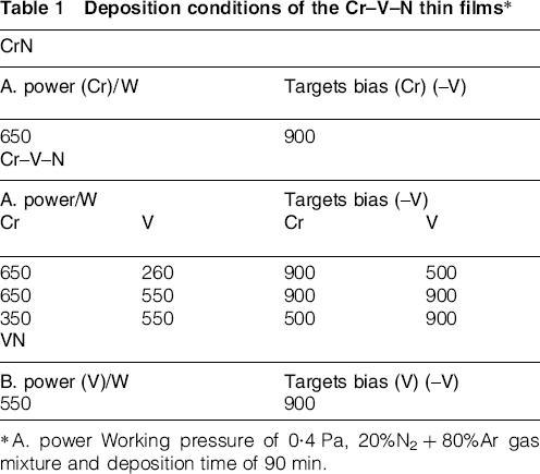
A. power Working pressure of 0·4 Pa, 20%N2+80%Ar gas mixture and deposition time of 90 min.
Results and discussion
Microstructure and chemical composition
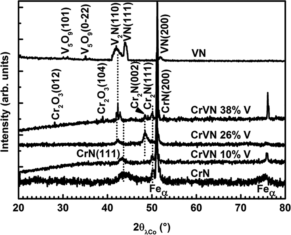
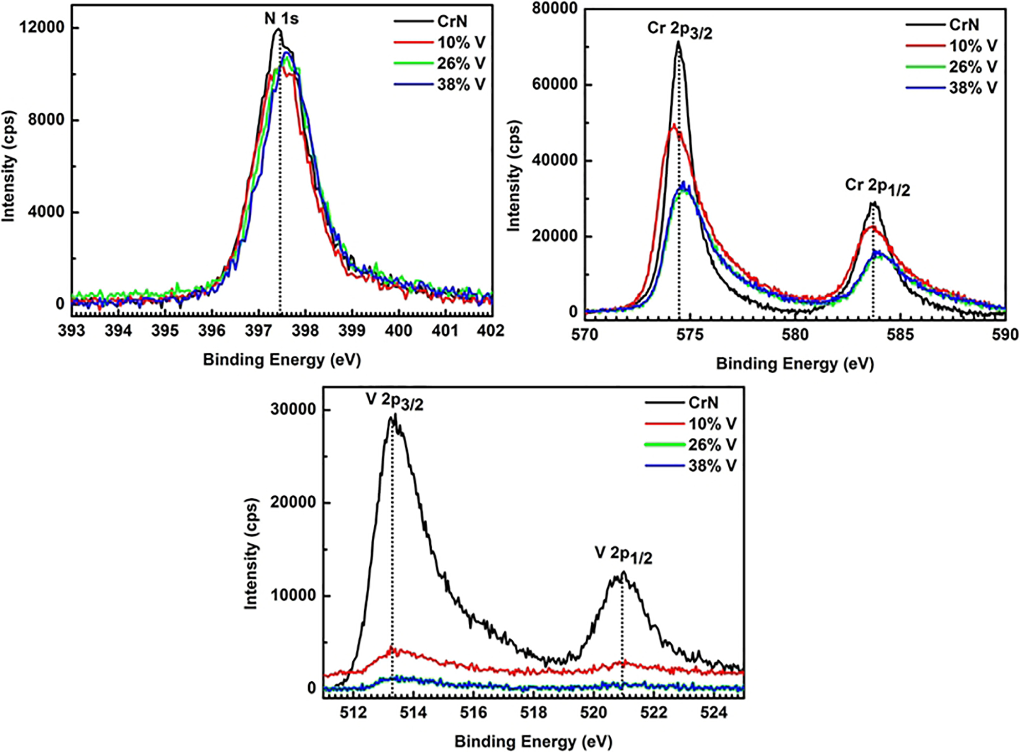
Chemical compositions of the Cr–V–N thin films are presented in Table 2. The CrN coating has an N/Cr atomic ratio ∼0·96; this is the characteristic of the cubic CrN phase. 12 Figure 1 shows the XRD patterns of the CrN, VN and Cr–V–N films, which are deposited on XC100 steel substrates. The Cr–N coating exhibits an NaCl cubic structure with a CrN (111) diffraction peak at 44·29° and a Cr2N (111) diffraction peak at 50·37°, which are similar to the observations in previous studies.13,14 The (111) diffraction peak of the CrN coating is shifted to a higher (2θ) angle by 0·41°, as compared to the JCPDS (00-011-0065) reference file; this is probably related to a compressive residual stress ( − 1·980 GPa), as it is shown in Table 2, which was possibly generated by the ion bombardment from the high applied power (650 W) in the plasma. Figure 2 shows the XPS spectra of Cr 2p, N 1s and V 2p for Cr–V–N films in each one with different Cr to V ratios. The XPS core level spectrum of N 1s shown in Fig. 2 exhibits almost a symmetric shape. For a pure CrN film, the Cr 2p3/2 binding energy is obtained at 574·40 eV. According to Conde et al., the peak corresponds to a CrN film for Cr–N bonds. 15 The N 1s spectrum shows a single wide peak at 397·1 eV. In addition, according to Barshilia et al., 16 this value probably corresponds to nitrogen in the CrN (397·0 eV), which gives a supplementary evidence supporting N element bonded to Cr during the coating deposition. The above results are in an excellent consistent with the XRD analysis.
Chemical composition and properties of Cr–V–N thin films
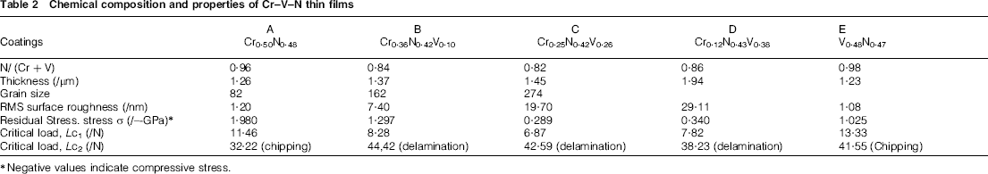
Negative values indicate compressive stress.
X-ray diffraction patterns of Cr–V–N thin films
X-ray photoelectron spectroscopy spectra for Cr–V–N thin films
Figure 3 shows the cross-sectional of Cr–V–N coatings, and Fig. 4 shows their top view SEM images. The CrN coating presents a compact columnar structure that appears to extend through the thickness of the coating. The average grain size of the CrN coating was estimated by the Scherrer formula using the (111) reflection, 6 which was 72 nm (Figs. 3a and 4a). Wang et al. 13 obtained the same structure on the CrN coatings prepared by unbalanced magnetron sputtering, however with a preferential (200) orientation. Because of the presence of both CrN and Cr2N phases in the CrN structure, as shown in the XRD pattern (Fig. 1), it is difficult to glean more quantitative information from the structural zone of this coating, This structure probably appears to be between the Ic zone and the transitional (T) zone according to Mahieu's model, 17 because the top of the columns are relatively flat, and the layer is also well crystallised. Ortmann et al. 18 showed a similar structure for CrN films deposited by plasma activated physical vapour deposition. The CrN coating thickness and RMS roughness (according to AFM observations) were 1·26 μm and 23·3 nm respectively. Table 2 shows the influence of the vanadium content on the overall chemical composition of the Cr–V–N coatings. The V content varies from 10 to 38 at-% (Table 2). As expected, the Cr content and the Cr applied power are decreased, whereas the V content increases with increased within V applied power. The nitrogen content of the coatings is relatively between 42 and 43 at-%. The diffraction patterns of the Cr–V–N layers (Fig. 1) indicate planar spacing, which is typical of the NaCl cubic structure with an overlap of both (111) and (200) orientations of CrN and VN. At 26 at-% of V, a broad Cr2N (002), a minor Cr2N (111) and also minor V2N (110) diffraction peaks are also detected. In addition, the Cr2O3 is detected in the Cr0·12V0·38N0·43 coating at 38 at-% of V. Within the Cr–V–N coatings, peak positions of Cr–V–N films are at lower angle than that of VN and CrN. This may suggests that Cr–V–N films consist of solid solution between CrN and, VN. On the other hand, the CrN (111) peak intensity gradually decreases with increasing V content and CrN and VN disappears entirely from the XRD pattern of the 38 at-% V coating. This may be due to the presence of an in plane compressive stress 19 and/or the substitution of V atoms into some Cr lattice sites. Unlike, the Cr2N (002) and (111), VN (111), and V2N (110) orientations gradually emerged in the XRD patterns; this can be related to the increase in the applied power of the V target. Similar results were observed for (V, Ti) N films, 20 where TiN diffraction peaks are not detected, because VN diffraction peaks are significantly stronger. This suggests that Cr–V–N films is composed of a solid solution of Cr and V, i.e. vanadium atoms substituted into chromium lattice sites. Previous studies have shown similar results for vanadium ions implanted into CrN films by metal vapour vacuum arc implantation, 13 and for Cr–V–N films deposited by cathodic arc ion plating method. 7 For the Cr–V–N films, the XPS analysis yields binding energies of Cr 2p3/2 and N 1s are (397·4 and 574·6 eV) at 10 at-% V and (397·6 and 574·8 eV) at 26 and 38 at-% V. In general, Cr 2p3/2 and N 1s shifted to high binding energies with the increase in the V content than that of CrN reference. The components observed would relate more to metallic Cr, which could be related to Cr2N, or, they correspond to Cr–N–O bonds, with some trace of Cr2O3 formed by insertion of oxygen. 15
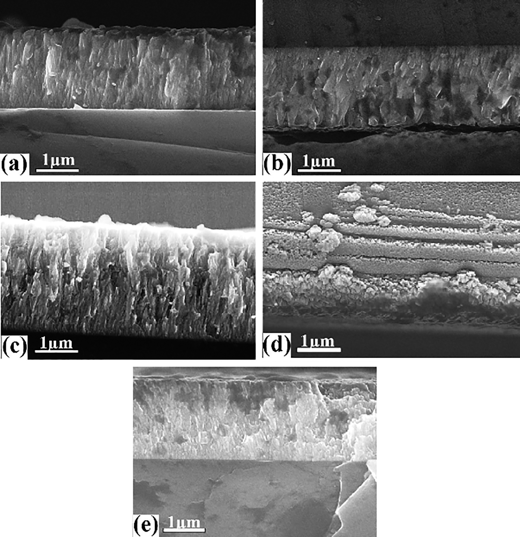
Cross-sectional SEM images of a CrN, Cr–V–N at b 10 at-% V, c 26 at-% V, d 38 at-% V and e VN thin films
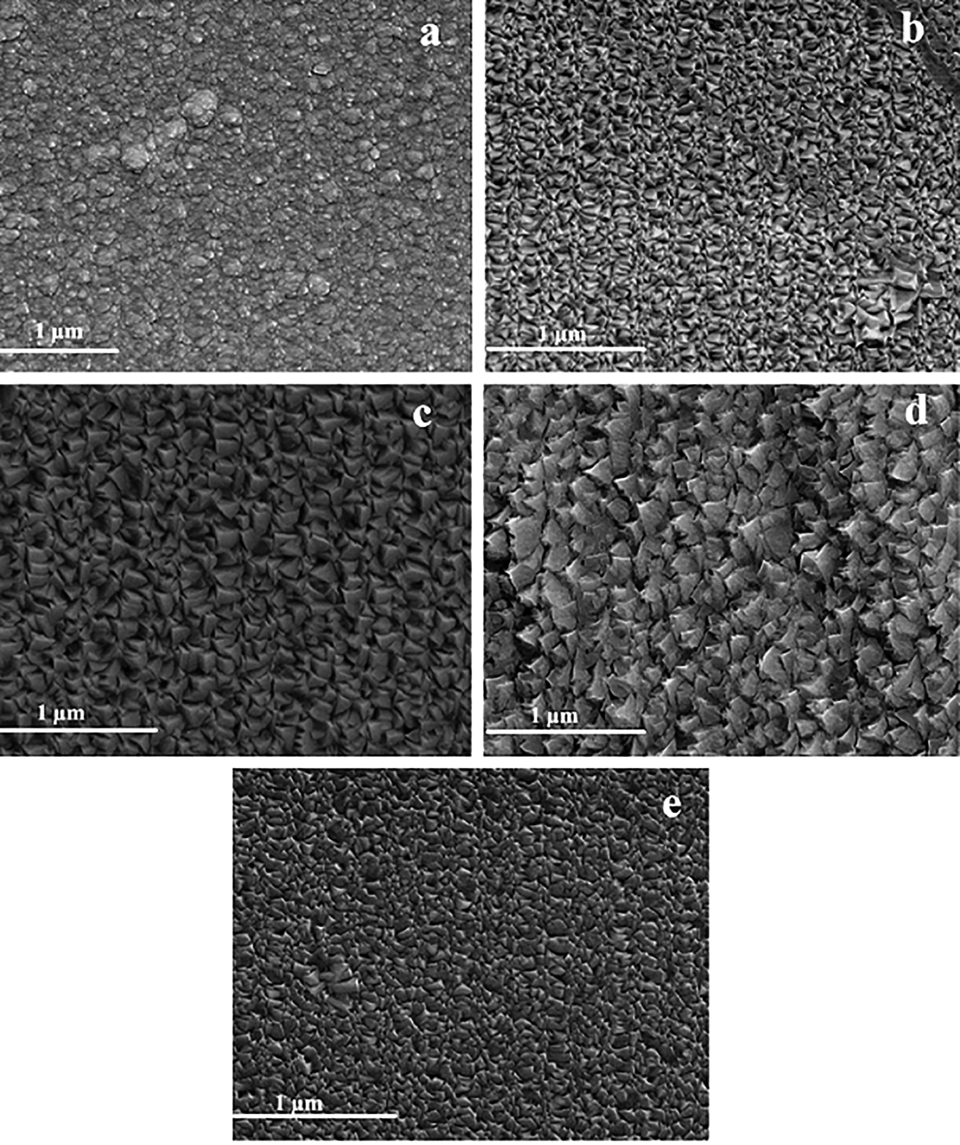
Surface morphologies (SEM) of a CrN, Cr–V–N at b 10 at-% V, c 26 at-% V, d 38 at-% V and e VN thin films
For the V 2p XPS peaks, between 10 and 26 at-% V, the V spectra did not give any information because of the feeble V concentration in the films. At 38 at-% of V content, the peak takes 513·42 eV with a small intensity. Compared to the one that is measured by Yang et al., the peak positions correspond to the VNx phase. 21 At 10 at-% V, a dense and a columnar structure with a pyramid-like surface (size ∼93 nm) is seen in Figs. 3b and 4b. At 26 at-% V, this microstructure very clearly coalesced to large grains (size ∼192 nm) as in Fig. 4c. For the film with 38 at-% of V, the surface shows more pronounced facets with even larger grains (∼245 nm) than that at 26 at-% V or at 10 at-% V (Fig. 4d ). In addition, this structure was observed for Ti–V–N and Ti–Al–N films deposited by reactive magnetron sputtering. 22
The change in the CrN film structure by adding the vanadium content is due to the change in the growth mechanism for the Cr–V–N coatings. Actually, for a low V power supply (or bias voltage) (260 W, − 500 V), it is expected there would be significantly less effects from ion bombardment than at a higher V power supply (550 W, − 900 V). Indeed, at low V power supply (10 at-% V), the film appears dense, with less defined columnar growth than those with high V content. Because, during the deposition, an energetic ion flux resulting from the sputtering effect and the heat of effective momentum transfer attacks the film surface and hence encourages diffusion. Thus, weakly deposited particles were removed and new precipitated compounds are formed, changing the surface morphological surface. Relating to Mahieu's model, the Cr–V–N films are clearly within the transition between zone T and zone 2 between 10 and 26 at-% V content. However, the high V content coatings appear to be near the transition to zone 2. 17 The influence of V content on Cr–V–N coating morphology is also evaluated by measuring the roughness and the film thickness. As a function of V content, optical profilometry and AFM analyses yield coating thicknesses (RMS roughness) of 1·37 μm (29·60 nm), 1·45 μm (56·39 nm) and 1·94 μm (86·17 nm) for 10, 26 and 38 at-% V (Table 2) respectively. This is possibly to a meager increase in the film thickness despite a high applied power due to a lower deposition rate of vanadium than chromium, and residual stresses are generated by the higher ion energy bombardment. This increase may be explained also with the atomic shadowing effect theory. Namely, during the film growth some of the crystalline orientations can be more favoured than the others, as the increase in the grain size leads to an increase in the surface roughness. This is similar to earlier observations of the Cr–N system deposited by magnetron sputtering technique. 23 The VN layer presents an N/V atomic ratio ∼0·98 with a nitrogen concentration of 48 at-%, indicating that the film is almost stoichiometric (Table 2). The XRD pattern of the VN coating is shown in Fig. 1. Two diffraction peaks VN (111) and (200) at 43·96 and 51·83° respectively referred to JCPDS (00-073-0528) and a minor V2N (110) at 43·03° JCPDS (00-032-1413) are detected; similar peaks were also detected in previous studies. 24 No apparent peak shift is observed for this film. Moreover, minor V5O9 (101) and (0–22) diffraction peaks are located at 30·58 and 35·50° JCPDS (00-018-1450) respectively. From the XPS analysis, a good correlation between the stoichiometry of the film and the binding energy positions of V and N1s peaks (513·40 and 397·3 eV) has been observed, which corresponded to a VN stoichiometry. The cross-section of VN coating presented a compact and columnar structure with a faceted surface (size ∼90 nm) (Fig. 3e). The VN surface did not show any discontinuity or defect, which refers to zone T in Mahieu's model. 17 In addition to this, the VN coating has a smaller thickness and lower RMS roughness (1·23 and 27·31 nm) than CrN (Table 2). Negligible oxygen concentration is detected in the pure CrN film; however, non-negligible amounts are detected in all Cr–V–N and VN films. Both Cr and V show strong affinities to oxygen. In addition, the mixing of these elements during deposition can form a strong base for the formation of oxides. 25 The oxygen contamination may be the result of a leak during coating deposition.
Mechanical properties
The hardness H and Young's modulus E of the studied coatings as a function of V content in the Cr–V–N layers are given in Fig. 5. The residual stress σ of all coatings is compressive and appears to follow the same trend as the coatings’ hardness and Young's modulus. The CrN film presents the higher hardness and Young's modulus (H = 19·53 GPa, E = 287 GPa). This may be due to its high stress level (Table 2) and dense structure 20 as observed in Fig. 3. Increasing the V content in the Cr–V–N system causes a drop in both hardness and Young's modulus. Nanoindentation tests yield hardness and Young's modulus of 11·27 and 239 GPa, 8·23 and 254 GPa and 5·27 and 223·39 GPa for coatings with 10, 26 and 38 at-% of V respectively (Fig. 5). For almost Cr–V–N coatings, the mechanical properties are lower than the XC100 substrate (H = 10·32 GPa, E = 226·13 GPa), while there are several possible reasons for the observed decline in mechanical properties. Jiang et al. 26 explained the decline via the surface roughness effect. Indeed, the higher surface roughness with larger grains in the high V films could alter the contact between the indenter tip and the surface of the sample. This would greatly affect the accuracy of the nanoindentation measurement in our case. Another possible explanation is that an actual decrease in the mechanical properties of the film is induced by the film growth mechanism. The typical growth mechanism for Cr–V–N films tends to form rough columnar structures, which are clearly observed in the surface micrographs of Fig. 4. This type of growth may introduce more voids in the structure. Porous ceramics compounds such as chromium carbides coatings have shown significantly a reduced hardnesses compared to their non-porous counterparts. 27 Moreover, Bouzakis et al. 28 explained the decline in the mechanical properties by the relaxation of residual stress with increasing film thickness, and the development of dominant V2N and Cr2N phases, which are less dense as compared to the CrN phase. Similar results are reported for Cr–V–N 7 and Ti–V–N 9 films obtained with high V content. Moreover, it is well known that the (111) orientation is the hardest for face centred cubic nitride films. 29 As well as the increase in V content, there is a decrease in the CrN (111) intensity that corresponds to the observed decrease in hardness. An additional reason for the mechanical properties decline is the high oxygen contamination of Cr–V–N coatings (Table 2). The oxygen (6 to 8 at-%) is typically bonded, forming oxides that may affect the coating mechanical properties in addition to this similar trends was observed on sputtered Cr–Zr–N 30 and W–Al–N films. 31 In our work, the low hardness values for Cr–V–N films may be due to the decrease in CrN (111) orientation, relaxation in the compressive stress, increased surface roughness and oxygen contamination. The pure VN film showed a slight increase in hardness and Young's modulus to 10·35 and 249 GPa. The average value of the Young's modulus is lower than that of polycrystalline vanadium nitride, which is typically 342 GPa. 9 The slight increase in the mechanical properties of the VN layer in comparison to the Cr–V–N ones is in agreement with the microstructure change (Fig. 4) because the shadowing effect is reduced and the voids in the microstructure are filled due to the surface diffusion of adatoms, which causes an improvement in mechanical properties. 32 In addition, this small rise in hardness can partly explained by the decrease in both grain size and RMS roughness. Unlike, the mechanical properties of the films are still poor in comparison to the CrN film. Latella et al. 9 found similar results when working within the TiVN system. Moreover, it may be useful to remember that the VN coating does suffer from significant oxygen contamination (4–5%), which will affect adversely the mechanical properties (7–8 at. %).
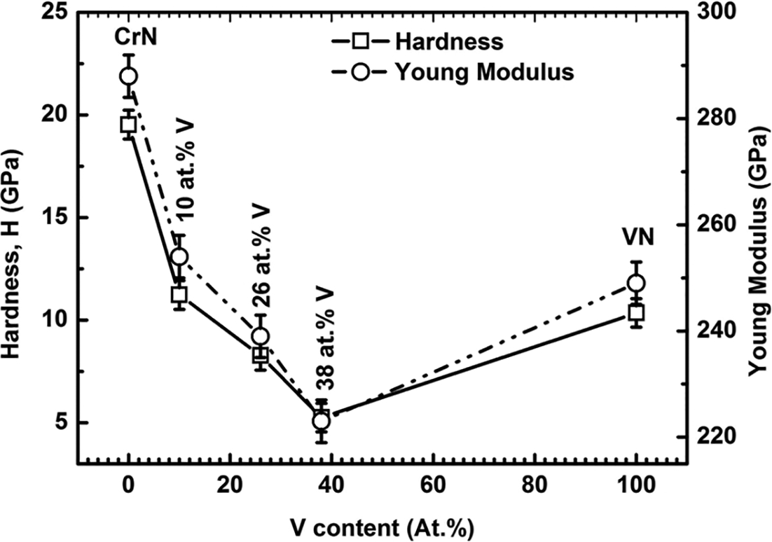
Hardness and Young's modulus of Cr–V–N thin films
Tribological properties
Friction coefficient
The evolution of the friction coefficient μ was determined by pin on disc tests as a function of the V and Cr contents (Fig. 6). Each test lasted 10 min under a 5 N load; a 100Cr6 steel ball was the counterpart. The average friction coefficient of the CrN film is 0·55, indicating that the CrN has a good abrasive resistance, as reported by Zhao et al. 33 However, the friction coefficient is slightly highly comparable to that exhibited by CrN films deposited on AISI 304 stainless steel sample by a PVD Alcatel SCM 450 sputtering system (0·50). 34 This difference is due to friction forces that are acting at the interface between the CrN coating and the substrate. In addition, the magnitude of those forces is related to the surface properties of the two materials. From Cr–V–N coatings, a clear trend was observed between the mechanical properties (hardness and Young's modulus) and the friction coefficient. In addition, similar results were obtained for ternary Ti–V–N coatings by Latella et al., 9 who explained this correlation by the dynamical behaviour of dislocations with the vanadium substitution of titanium atoms in the film structure. However, Sarakinos et al. 35 explained this result by the change in the micro/nanostructure of carbon based compounds, which possessed similar tribological parameters. Compared with the friction coefficient of CrN coating (0·55), the Cr–V–N coatings have a slightly lower friction coefficient of ∼0·39. According to Yuexiu et al., 4 this is attributed to the contamination of the Cr–V–N coating by oxygen, and formation of oxides. These oxides act as a lubricant between two counterparts. 4 In addition, the presence of these composes in the film contributes to the low coefficient of friction. For VN film, the friction coefficient is 0·42 against 100Cr6 ball, which is in good agreement with the measurements of VN coatings, which is deposited by unbalanced magnetron sputtering by Fateh et al. 36 However, it is significantly higher than VN films (0·33) deposited by DC magnetron sputtering. The VN coating exhibited a lower friction coefficient than CrN coating (Fig. 6), while the lower surface roughness of the VN coating is contributing to the lower friction coefficient. In similar results of VN films by Yuexiu et al., 4 who explained the low friction coefficient of VN film by the presence of vanadium oxides at its surface. As with the Cr–V–N coating, also the presence of oxides within the film may play a role in the reduced coefficient of friction.
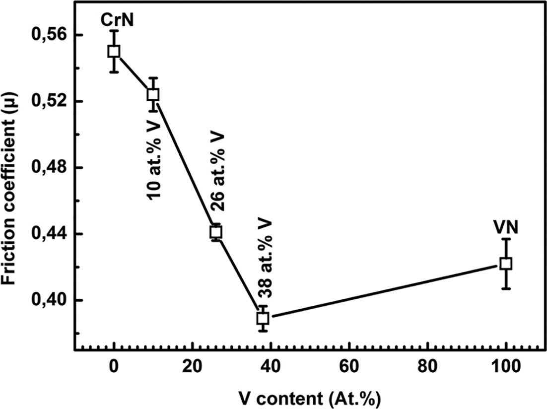
Friction coefficient of Cr–V–N thin films
Scratch tests
Scratch tests were carried out to investigate the adhesion between the coatings and the XC100 steel substrates. Two critical loads were defined: the cohesive failure critical load Lc1, corresponding to the beginning of cracking in the coatings, and the adhesion failure critical load Lc2, corresponding to the chipping or the delamination of coatings. 35 Lc1 and Lc2 versus the V content are presented in Table 2. The scratch tracks of the coatings deposited at various V content were observed by optical microscopy as shown in Fig. 7. It is obvious in (Table 2) that the critical loads followed a similar trend as the friction coefficient, but the inverse tendency to the RMS roughness lower RMS roughness values resulted in higher critical loads. For the CrN coating, cohesive failure occurs at ∼11·46 N. The failure mechanism appears to be conformal cracking in the scratch track (Fig. 7a); these kinds of cracks are often associated with a hard coating (CrN) coupled to a soft substrate (XC100). 36 The chipping at the edge of the scratch track appears to be the initial stage for the adhesive failure of chromium nitride coating. The adhesive failure critical load Lc2 has a medium value of 32·2 N. However, this is lower as compared with the adhesion properties of CrN deposited by an ion plating PVD process onto X37CrMoV5-1 steel, 37 which can be attributed to the presence of a high residual stress and a soft substrate. For the Cr–V–N coatings, the cohesive failures are significantly lower (6·9–8·3 N). However, adhesive failure occurred at higher critical loads, ranging from 44·4 N for 10 at-% V and then decreased slightly to 38·2 N with the 38 at-% V coating. Thus, it appears that the addition of V to the CrN system has improved the adhesion of the layers. This may be explained by a reduction in the coatings’ residual stress with the addition of V to the Cr–V–N system. In addition, the Lc2 values are inversely proportional to the residual stress in the case of Cr–Al–N films. 38 Moreover, a different failure mechanism can be seen during the scratch testing of Cr–V–N coatings (Fig. 7). Similar to CrN coatings, the initial chipping/spallation occurs at the edge of the scratch track. However, with the Cr–V–N coatings, this behaviour extends past the edge of the coating onto the surface of the sample. In addition, this coating failure and removal appear more complete as several areas of the steel substrate were exposed. In addition, there is significantly more debris along the edge of the track in the initial failure (Lc1 < 10 N), while a complete failure of the Cr–V–N coatings occurred at higher critical loads, and this may be due to their weak structure cohesion. Moreover, the addition of V decreases the friction coefficient, which can be an indicator of the coatings resistance to abrasion, i.e. lower coefficients of friction correlate with low critical loads for cohesive failure.

Micrographs of scratch tracks of a CrN, Cr–V–N at b 10 at-% V, c 26 at-% V, d 38 at-% V and e VN thin films
The VN coating (Table 2) has a significantly better Lc1 (up to 13·3 N) when it is compared to the Cr–V–N coatings. Moreover, the critical load of adhesive failure was on the same order of magnitude (41·5 N). In both cases (cohesive and adhesive failure), this is an improvement over the CrN coating. Yoshida et al. 39 showed that for very soft coatings (hardness is on the order of 5 GPa), the films could resist plastic deformation. Nevertheless, when the coatings failed, there was interfacial spallation along the scratch track borders (Fig. 7e) and the VN coating flaked off the edge of the scratch track as well as the stylus passed by. These dramatic failures may originate from the coating's small thickness, and the differences in the mechanical properties between the coating and substrate.
Conclusion
Cr–V–N coatings were deposited onto Si and XC100 steel substrates by RF dual magnetron sputtering. The structure, morphology, mechanical and tribological properties of the coatings were characterised. The results permit us to sum up as follows.
Both the pure CrN and VN films are well crystallised. The CrN coating is very dense and presents good mechanical and tribological properties. From the XRD and EDS analyses, the Cr–V–N coatings appear to be composed of a solid solution, with vanadium substitution at chromium sites and exhibit a faceted grain structure with pyramid-like forms. The mechanical and tribological properties of the Cr–V–N coatings were lower than that either the CrN or VN binary coatings are excepted in terms of COF. This may be due to the rough morphological surface and/or oxygen contamination. In this study, the addition of vanadium did not improve the mechanical and tribological properties of the Cr–N system.
Acknowledgements
The authors would like to thank Mr Gildas Guillemot for the mechanical and tribological measurements carried out at Arts et Metiers ParisTech of Lille and Mr IMHOFF for the SEM and EDS analysis of the test samples at ICB in Dijon. The authors are also grateful to the whole group of LaBoMaP at Arts et Metiers ParisTech of Cluny for their help in the deposition of coatings, the EDS or XRD analyses and residual stresses measurements.